C02 SUZUKI SWIFT 2007 2.G Service Workshop Manual
[x] Cancel search | Manufacturer: SUZUKI, Model Year: 2007, Model line: SWIFT, Model: SUZUKI SWIFT 2007 2.GPages: 1496, PDF Size: 34.44 MB
Page 40 of 1496
Downloaded from www.Manualslib.com manuals search engine 0B-10 Maintenance and Lubrication:
Steering System InspectionS7RS0B0206024
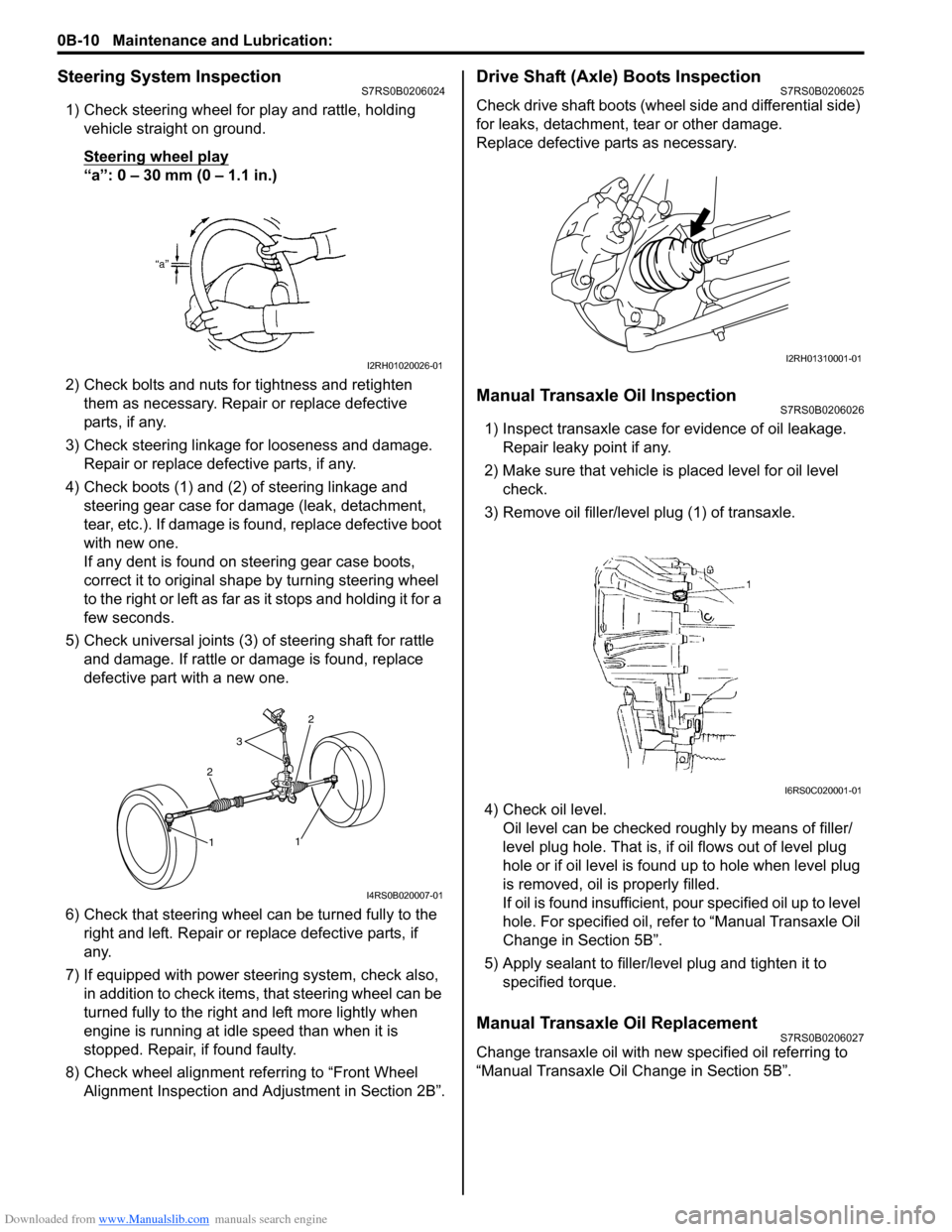
1) Check steering wheel for play and rattle, holding vehicle straight on ground.
Steering wheel play
“a”: 0 – 30 mm (0 – 1.1 in.)
2) Check bolts and nuts for tightness and retighten them as necessary. Repair or replace defective
parts, if any.
3) Check steering linkage for looseness and damage. Repair or replace defective parts, if any.
4) Check boots (1) and (2) of steering linkage and steering gear case for damage (leak, detachment,
tear, etc.). If damage is fo und, replace defective boot
with new one.
If any dent is found on steering gear case boots,
correct it to original shape by turning steering wheel
to the right or left as far as it stops and holding it for a
few seconds.
5) Check universal joints (3) of steering shaft for rattle and damage. If rattle or damage is found, replace
defective part with a new one.
6) Check that steering wheel can be turned fully to the
right and left. Repair or replace defective parts, if
any.
7) If equipped with power steering system, check also, in addition to check items, that steering wheel can be
turned fully to the right and left more lightly when
engine is running at idle speed than when it is
stopped. Repair, if found faulty.
8) Check wheel alignment referring to “Front Wheel Alignment Inspection and Adjustment in Section 2B”.
Drive Shaft (Axle) Boots InspectionS7RS0B0206025
Check drive shaft boots (wheel side and differential side)
for leaks, detachment, tear or other damage.
Replace defective parts as necessary.
Manual Transaxle Oil InspectionS7RS0B0206026
1) Inspect transaxle case for evidence of oil leakage. Repair leaky point if any.
2) Make sure that vehicle is placed level for oil level
check.
3) Remove oil filler/leve l plug (1) of transaxle.
4) Check oil level. Oil level can be checked roughly by means of filler/
level plug hole. That is, if oil flows out of level plug
hole or if oil level is found up to hole when level plug
is removed, oil is properly filled.
If oil is found insufficient, po ur specified oil up to level
hole. For specified oil, refe r to “Manual Transaxle Oil
Change in Section 5B”.
5) Apply sealant to filler/leve l plug and tighten it to
specified torque.
Manual Transaxle Oil ReplacementS7RS0B0206027
Change transaxle oil with new specified oil referring to
“Manual Transaxle Oil Change in Section 5B”.
I2RH01020026-01
2
3
2
1
1
I4RS0B020007-01
I2RH01310001-01
I6RS0C020001-01
Page 1178 of 1496
Downloaded from www.Manualslib.com manuals search engine 9A-7 Wiring Systems:
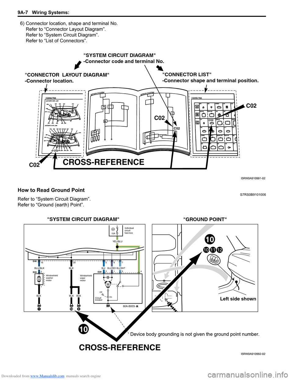
6) Connector location, shape and terminal No.Refer to “Connector Layout Diagram”.
Refer to “System Circuit Diagram”.
Refer to “List of Connectors”.
How to Read Ground PointS7RS0B9101006
Refer to “System Circuit Diagram”.
Refer to “Ground (earth) Point”.
"SYSTEM CIRCUIT DIAGRAM"
-Connector code and terminal No.
"CONNECTOR LAYOUT DIAGRAM"
-Connector location.
CROSS-REFERENCE
"CONNECTOR LIST"
-Connector shape and terminal position.
C02
C02 C02
C02
C02
C02
I5RW0A910991-02
Left side shown
101112
"SYSTEM CIRCUIT DIAGRAM"
"GROUND POINT"
CROSS-REFERENCE
Windoshield
washer
motor Individual
circuit
fuse box
2015A
Windoshield
wiper
motor
E40
E09
E20
16
2
1
Off
On
Circuit
breaker
60A-B003-
YEL/BLU
1
205
2
134
67
BLU/BLK
BLK
10
BLK
BLK
9
10
10
BLK
M
BLUBLU/WHTBLU/RED
M
Device body grounding is not given the ground point number.
I5RW0A910992-02
Page 1181 of 1496
Downloaded from www.Manualslib.com manuals search engine Wiring Systems: 9A-10
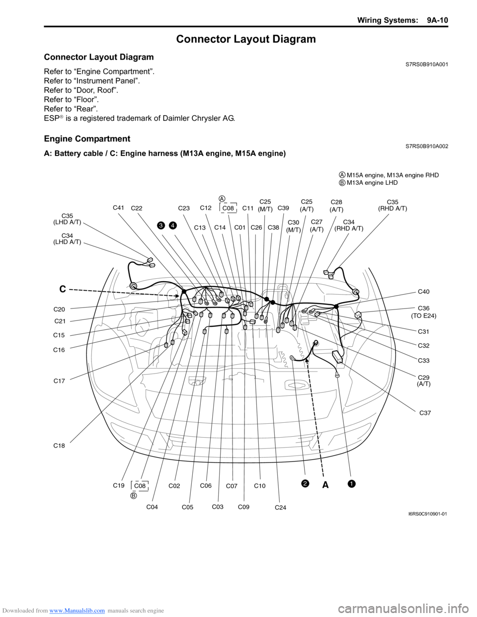
Connector Layout Diagram
Connector Layout DiagramS7RS0B910A001
Refer to “Engine Compartment”.
Refer to “Instrument Panel”.
Refer to “Door, Roof”.
Refer to “Floor”.
Refer to “Rear”.
ESP
® is a registered trademark of Daimler Chrysler AG.
Engine CompartmentS7RS0B910A002
A: Battery cable / C: Engine harness (M13A engine, M15A engine)
A
C36
(TO E24)
C17
C18
C19 C35
(RHD A/T)
C34
(LHD A/T) C35
(LHD A/T) C34
(RHD A/T)
C37
C15
C16
C02C08
C03
C10
C0912
34
C31
C32
C33
C29
(A/T)
C28
(A/T)
C27
(A/T)C30
(M/T) C25
(A/T)
C24
C25
(M/T)
C26
C07
C06
C05
C04
C22
C21
C20 C23
C13
C12C14
C08
C01
CC40
C41C39
C38C11
A
A
B
BM15A engine, M13A engine RHD
M13A engine LHD
I6RS0C910901-01
Page 1182 of 1496

Downloaded from www.Manualslib.com manuals search engine 9A-11 Wiring Systems:
C: Engine harnessNo./Color Connective position No./Color Connective positionC01/GRY IAC valve C22/- Generator #2
C02/GRY IG Coil #1 C23/BLK Starting motor #1
C03/GRY IG Coil #2 C24/- Starting motor #2
C04/GRY Fuel injector #1 C25/GR Y VSS (Vehicle speed sensor)
C05/GRY Fuel injector #2 C26/GRY Knock sensor
C06/GRY Fuel injector #3 C27/BLU (A/
T) Input shaft speed sensor
C07/GRY Fuel injector #4 C28/GRY
(A/T) Trans axle range sensor
C08/BLK or GRY CMP sensor C29/GRY
(A/T) Shift solenoid
C09/BLK ECT sensor C30/BLK
(M/T) Back-up light switch
C10/GRY EGR stepper motor C31/- Main fuse box C11/BLK Throttle position sensor C32/GRY
(IF EQPD) Current sensor
C12/BLK MAP sensor C33/- Main fuse box
C13/BLK MAF sensor C34/N (A/T) TCM
C14/BLK EVAP canister purge valve C35/N (A/T) TCM
C15/GRY Heated oxygen sensor #1 C36/N Main harness (To E24)
C16/GRN Heated oxygen sensor #2 C37/GRY ECM C17/BLK A/C compressor C38/- Weld splice C18/N Oil pressure switch C39/- Weld splice
C19/BLU VVT solenoid C40/- Weld splice
C20/GRY CKP sensor C41/- Weld splice
C21/GRY or BLK Generator #1
Page 1183 of 1496
Downloaded from www.Manualslib.com manuals search engine Wiring Systems: 9A-12
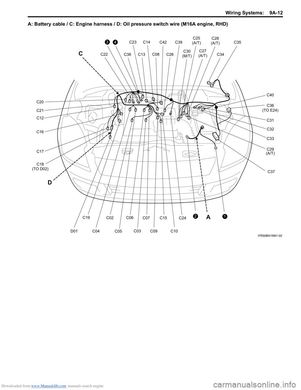
A: Battery cable / C: Engine harness / D: Oil pressure switch wire (M16A engine, RHD)
C36
(TO E24)
C35
C34
C37
34
C31
C32
C33
C29
(A/T)
C28
(A/T)
C27
(A/T)C30
(M/T) C25
(A/T)C26C22 C23C13C38
C14
C08
C40
C39
C42
A
C17
C18
(TO D02)
C19
C16
C02
C03C10
C09
12C24C07C15
C06
C05
C04D01
C21
C12
C20
C
D
I7RS0B910901-02
Page 1184 of 1496

Downloaded from www.Manualslib.com manuals search engine 9A-13 Wiring Systems:
C: Engine harness
D: Oil pressure switch wireNo./Color Connective position No./Color Connective position
C02/GRY IG Coil #1 C24/- Starting motor #2
C03/GRY IG Coil #2 C23/BLK Starting motor #1
C04/GRY Fuel injector #1 C25/GRY
(A/T) VSS (Vehicle speed sensor)
C05/GRY Fuel injector #2 C26/GRY Knock shaft speed sensor
C06/GRY Fuel injector #3 C27/BLU (A/
T) Input shaft speed sensor
C07/GRY Fuel injector #4 C28/GRY
(A/T) Trans axle range sensor
C08/BLK CMP sensor C29/GRY
(A/T) Shift solenoid
C09/BLK ECT sensor C30/BLK
(M/T) Back-up light switch
C10/GRY EGR stepper motor C31/- Main fuse box C12/BLK MAP sensor C32/GRY Current sensor
C13/BLK MAF sensor C33/- Main fuse box
C14/BLK EVAP canister purge valve C34/N (A/T) TCM
C15/BLK Heated oxygen sensor #1 C35/N (A/T) TCM
C16/GRN Heated oxygen sensor #2 C36/N Main harness (To E24) C17/BLK A/C compressor C37/GRY ECM C18/N Oil pressure switch wire (To D02) C38/- Weld splice
C19/BLU VVT solenoid C39/- Weld splice
C20/GRY CKP sensor C40/- Weld splice C21/BLK Generator #1 C42/BLK Electric throttle body C22/- Generator #2
No./Color Connective position No./ColorConnective position
D01/N Oil pressure switch D02/GRY Engine harness (To C18)
Page 1219 of 1496
Downloaded from www.Manualslib.com manuals search engine Wiring Systems: 9A-48
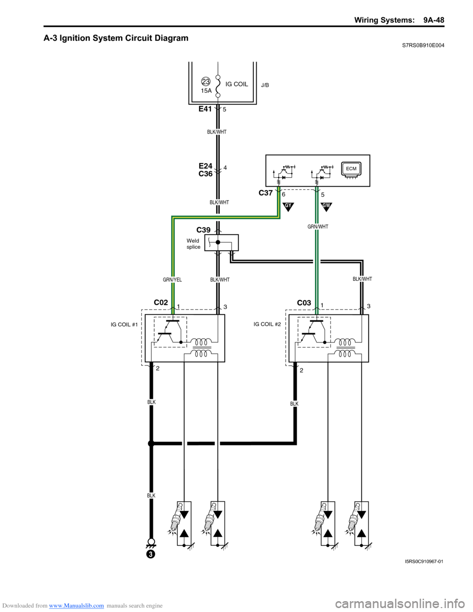
A-3 Ignition System Circuit DiagramS7RS0B910E004
15A
4E24
C36
2
C021 3
IG COIL #1
C03
BLK
BLK/WHTGRN/YEL
BLK/WHT
J/B
ECM
GYGW
23IG COIL
BLK
BLK
IG COIL #2
E415
3
GRN/WHT
1
3
2
C375
6
Weld
splice
C39
BLK/WHT
BLK/WHT
I5RS0C910967-01
Page 1274 of 1496
Downloaded from www.Manualslib.com manuals search engine 9A-103 Wiring Systems:
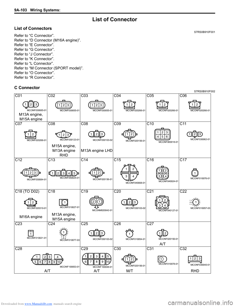
List of Connector
List of ConnectorsS7RS0B910F001
Refer to “C Connector”.
Refer to “D Connector (M16A engine)”.
Refer to “E Connector”.
Refer to “G Connector”.
Refer to “J Connector”.
Refer to “K Connector”.
Refer to “L Connector”.
Refer to “M Connector (SPORT model)”.
Refer to “O Connector”.
Refer to “R Connector”.
C ConnectorS7RS0B910F002
C01C02C03 C04 C05 C06
M13A engine, M15A engine
C07 C08C08 C09 C10 C11
M15A engine, M13A engine RHD M13A engine LHD
C12 C13C14 C15 C16 C17
C18 (TO D02) C18 C19C20C21C22
M16A engine M13A engine,
M15A engine
C23 C24C25 C26 C27
A/T
C28 C29C30C31C32
A/T A/TM/T RHD
1
23
MCONF030085-01
123
MCONF030055-01
123
MCONF030055-01
12
MCONF020266-01
12
MCONF020266-01
12
MCONF020266-01
12
MCONF020266-01
123
MCONF030123-01
123
MCONF030103-02
12
MCONF020156-01
123
456
MCONF060018-01
123
MCONF030062-01
123
MCONF030084-01
14325
MCONF050025-01
12
MCONF020156-01
12
34
MCONF040008-01
1
2
3 4
MCONF040024-01
1
MCONF010076-01
12
MCONF020310-01
1
MCONF010027-01
21
MCONM020042-01
12
3
MCONF030103-02
21
43
MCONF040127-01
1
MCONF010057-03
1MCONF010021-01
1
MCONF010077-03
123
MCONF030103-02
1
MCONF010054-01
1
2
MCONF020150-01
1
5678910 23 4
MCONF100053-01
1
2 5
6 7
103
84
9
MCONF100048-01
12
MCONF020156-01
1
MCONF010078-01
123
MCONF030040-01