C16 SUZUKI SWIFT 2007 2.G Service Workshop Manual
[x] Cancel search | Manufacturer: SUZUKI, Model Year: 2007, Model line: SWIFT, Model: SUZUKI SWIFT 2007 2.GPages: 1496, PDF Size: 34.44 MB
Page 365 of 1496
Downloaded from www.Manualslib.com manuals search engine Engine Cooling System: 1F-2
Coolant capacity
For M/T model:• Engine, radiator and heater: 5.5 liters (11.62/9.68 US/lmp pt.)
• Reservoir: 0.7 liters (1.48/1.23 US/lmp pt.)
• Total: 6.2 liters (13.10/10.91 US/lmp pt.)
For A/T model: • Engine, radiator and heater: 5.4 liters (11.41/9.50 US/lmp pt.)
• Reservoir: 0.7 liters (1.48/1.23 US/lmp pt.)
• Total: 6.1 liters (12.89/10.74 US/lmp pt.)
Schematic and Routing Diagram
Coolant CirculationS7RS0B1602001
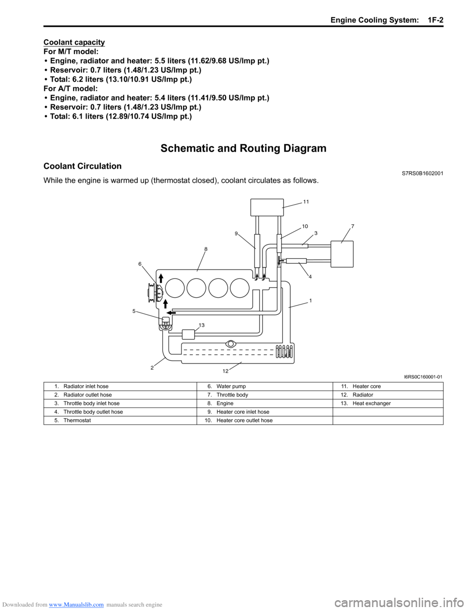
While the engine is warmed up (thermosta t closed), coolant circulates as follows.
11
10 3 7
4
9
8
6
5
2 12 1
13
I6RS0C160001-01
1. Radiator inlet hose
6. Water pump11. Heater core
2. Radiator outlet hose 7. Throttle body12. Radiator
3. Throttle body inlet hose 8. Engine13. Heat exchanger
4. Throttle body outlet hose 9. Heater core inlet hose
5. Thermostat 10. Heater core outlet hose
Page 366 of 1496
Downloaded from www.Manualslib.com manuals search engine 1F-3 Engine Cooling System:
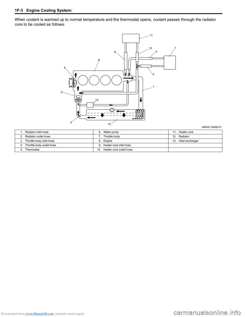
When coolant is warmed up to normal temperature and the thermostat opens, coolant passes through the radiator
core to be cooled as follows.
11
10 3 7
4
9
8
6
5
2 12 1
13
I6RS0C160002-01
1. Radiator inlet hose
6. Water pump11. Heater core
2. Radiator outlet hose 7. Throttle body12. Radiator
3. Throttle body inlet hose 8. Engine13. Heat exchanger
4. Throttle body outlet hose 9. Heater core inlet hose
5. Thermostat 10. Heater core outlet hose
Page 418 of 1496
Downloaded from www.Manualslib.com manuals search engine 1J-8 Charging System:
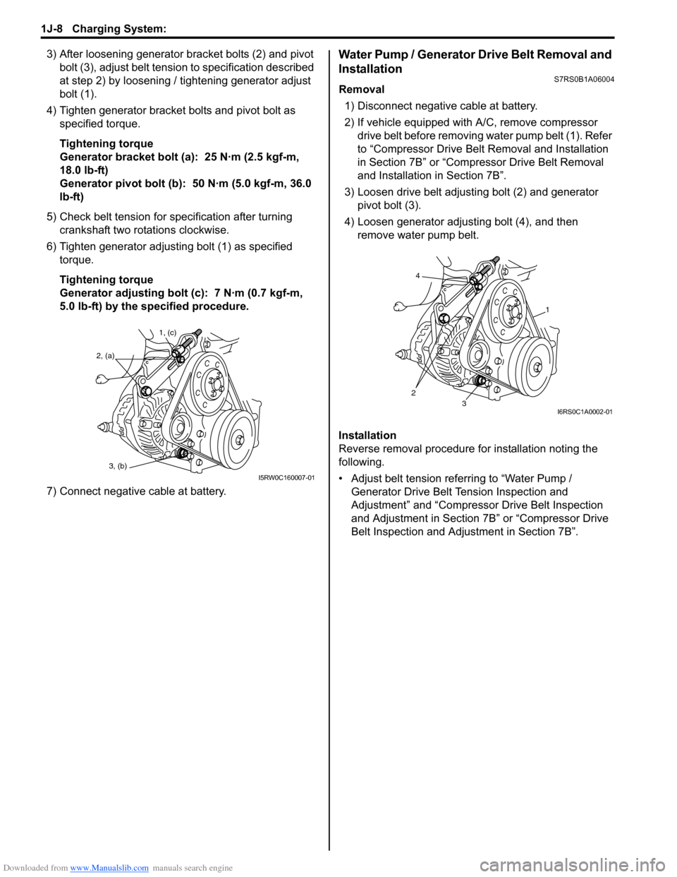
3) After loosening generator bracket bolts (2) and pivot bolt (3), adjust belt tensio n to specification described
at step 2) by loosening / tightening generator adjust
bolt (1).
4) Tighten generator bracket bolts and pivot bolt as specified torque.
Tightening torque
Generator bracket bolt (a): 25 N·m (2.5 kgf-m,
18.0 lb-ft)
Generator pivot bolt (b): 50 N·m (5.0 kgf-m, 36.0
lb-ft)
5) Check belt tension for specification after turning crankshaft two rotations clockwise.
6) Tighten generator adjusting bolt (1) as specified torque.
Tightening torque
Generator adjusting bolt (c): 7 N·m (0.7 kgf-m,
5.0 lb-ft) by the specified procedure.
7) Connect negative cable at battery.Water Pump / Generator Drive Belt Removal and
Installation
S7RS0B1A06004
Removal 1) Disconnect negative cable at battery.
2) If vehicle equipped with A/C, remove compressor drive belt before removing water pump belt (1). Refer
to “Compressor Drive Belt Removal and Installation
in Section 7B” or “Compr essor Drive Belt Removal
and Installation in Section 7B”.
3) Loosen drive belt adjusting bolt (2) and generator pivot bolt (3).
4) Loosen generator adjusting bolt (4), and then remove water pump belt.
Installation
Reverse removal procedure for installation noting the
following.
• Adjust belt tension referring to “Water Pump / Generator Drive Belt Tension Inspection and
Adjustment” and “Compressor Drive Belt Inspection
and Adjustment in Section 7B” or “Compressor Drive
Belt Inspection and Adjustment in Section 7B”.
1, (c)
2, (a)
3, (b)
I5RW0C160007-01
4
23
1
I6RS0C1A0002-01
Page 1181 of 1496
Downloaded from www.Manualslib.com manuals search engine Wiring Systems: 9A-10
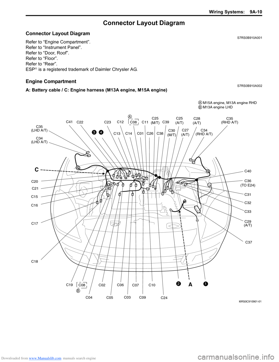
Connector Layout Diagram
Connector Layout DiagramS7RS0B910A001
Refer to “Engine Compartment”.
Refer to “Instrument Panel”.
Refer to “Door, Roof”.
Refer to “Floor”.
Refer to “Rear”.
ESP
® is a registered trademark of Daimler Chrysler AG.
Engine CompartmentS7RS0B910A002
A: Battery cable / C: Engine harness (M13A engine, M15A engine)
A
C36
(TO E24)
C17
C18
C19 C35
(RHD A/T)
C34
(LHD A/T) C35
(LHD A/T) C34
(RHD A/T)
C37
C15
C16
C02C08
C03
C10
C0912
34
C31
C32
C33
C29
(A/T)
C28
(A/T)
C27
(A/T)C30
(M/T) C25
(A/T)
C24
C25
(M/T)
C26
C07
C06
C05
C04
C22
C21
C20 C23
C13
C12C14
C08
C01
CC40
C41C39
C38C11
A
A
B
BM15A engine, M13A engine RHD
M13A engine LHD
I6RS0C910901-01
Page 1182 of 1496

Downloaded from www.Manualslib.com manuals search engine 9A-11 Wiring Systems:
C: Engine harnessNo./Color Connective position No./Color Connective positionC01/GRY IAC valve C22/- Generator #2
C02/GRY IG Coil #1 C23/BLK Starting motor #1
C03/GRY IG Coil #2 C24/- Starting motor #2
C04/GRY Fuel injector #1 C25/GR Y VSS (Vehicle speed sensor)
C05/GRY Fuel injector #2 C26/GRY Knock sensor
C06/GRY Fuel injector #3 C27/BLU (A/
T) Input shaft speed sensor
C07/GRY Fuel injector #4 C28/GRY
(A/T) Trans axle range sensor
C08/BLK or GRY CMP sensor C29/GRY
(A/T) Shift solenoid
C09/BLK ECT sensor C30/BLK
(M/T) Back-up light switch
C10/GRY EGR stepper motor C31/- Main fuse box C11/BLK Throttle position sensor C32/GRY
(IF EQPD) Current sensor
C12/BLK MAP sensor C33/- Main fuse box
C13/BLK MAF sensor C34/N (A/T) TCM
C14/BLK EVAP canister purge valve C35/N (A/T) TCM
C15/GRY Heated oxygen sensor #1 C36/N Main harness (To E24)
C16/GRN Heated oxygen sensor #2 C37/GRY ECM C17/BLK A/C compressor C38/- Weld splice C18/N Oil pressure switch C39/- Weld splice
C19/BLU VVT solenoid C40/- Weld splice
C20/GRY CKP sensor C41/- Weld splice
C21/GRY or BLK Generator #1
Page 1183 of 1496
Downloaded from www.Manualslib.com manuals search engine Wiring Systems: 9A-12
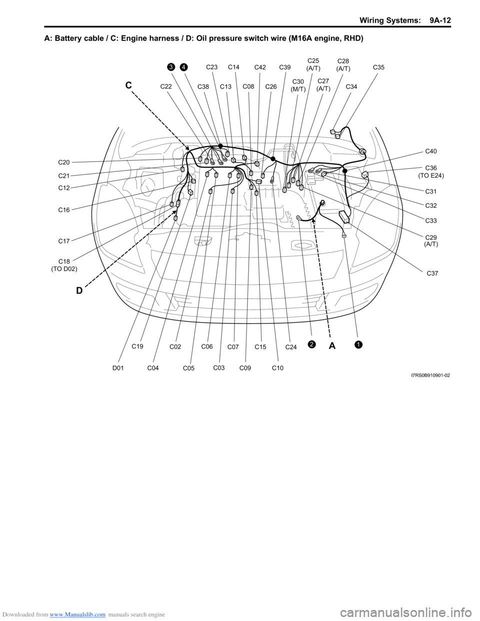
A: Battery cable / C: Engine harness / D: Oil pressure switch wire (M16A engine, RHD)
C36
(TO E24)
C35
C34
C37
34
C31
C32
C33
C29
(A/T)
C28
(A/T)
C27
(A/T)C30
(M/T) C25
(A/T)C26C22 C23C13C38
C14
C08
C40
C39
C42
A
C17
C18
(TO D02)
C19
C16
C02
C03C10
C09
12C24C07C15
C06
C05
C04D01
C21
C12
C20
C
D
I7RS0B910901-02
Page 1184 of 1496

Downloaded from www.Manualslib.com manuals search engine 9A-13 Wiring Systems:
C: Engine harness
D: Oil pressure switch wireNo./Color Connective position No./Color Connective position
C02/GRY IG Coil #1 C24/- Starting motor #2
C03/GRY IG Coil #2 C23/BLK Starting motor #1
C04/GRY Fuel injector #1 C25/GRY
(A/T) VSS (Vehicle speed sensor)
C05/GRY Fuel injector #2 C26/GRY Knock shaft speed sensor
C06/GRY Fuel injector #3 C27/BLU (A/
T) Input shaft speed sensor
C07/GRY Fuel injector #4 C28/GRY
(A/T) Trans axle range sensor
C08/BLK CMP sensor C29/GRY
(A/T) Shift solenoid
C09/BLK ECT sensor C30/BLK
(M/T) Back-up light switch
C10/GRY EGR stepper motor C31/- Main fuse box C12/BLK MAP sensor C32/GRY Current sensor
C13/BLK MAF sensor C33/- Main fuse box
C14/BLK EVAP canister purge valve C34/N (A/T) TCM
C15/BLK Heated oxygen sensor #1 C35/N (A/T) TCM
C16/GRN Heated oxygen sensor #2 C36/N Main harness (To E24) C17/BLK A/C compressor C37/GRY ECM C18/N Oil pressure switch wire (To D02) C38/- Weld splice
C19/BLU VVT solenoid C39/- Weld splice
C20/GRY CKP sensor C40/- Weld splice C21/BLK Generator #1 C42/BLK Electric throttle body C22/- Generator #2
No./Color Connective position No./ColorConnective position
D01/N Oil pressure switch D02/GRY Engine harness (To C18)
Page 1221 of 1496
Downloaded from www.Manualslib.com manuals search engine Wiring Systems: 9A-50
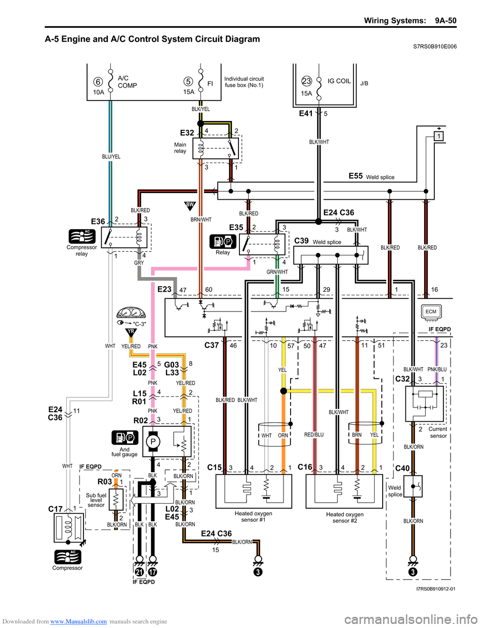
A-5 Engine and A/C Control System Circuit DiagramS7RS0B910E006
YEL/RED
E45L02 G03
L33
L02
E4558
L15
R0142
PNKYEL/RED
P
PNKYEL/RED
31
3
3 1
E24 C36
BLK/ORN
BLK/ORN
BLK/ORN
BLK/ORN
3
15
BLK
42
R02
1
2
R03
And
fuel gauge
Sub fuel level
sensor
Main
relay
1BLK/WHT
BLK/WHT
C39Weld splice Weld splice
E55
GRN/WHT
IG COILJ/B5
15A
FI
BLK/YEL
E324
32
1 15A
23
BRN/WHT
BW
YR
6
10A
A/C
COMP
Compressor
relay
E36
Relay
BLU/YEL
Compressor
C171
E415
E24 C36
3
E24
C3611
BLK/WHT
C15 C16
Heated oxygen
sensor #1
BLK/RED
WHT
Heated oxygensensor #2
BRN
BLK/WHT
RED/BLU
C37
34213421
4610574711
YEL
5123PNK
ECM
41 3
2
WHT
WHT
BLK/REDBLK/RED
BLK/RED
E23476015291
GRY
E3523
1
4
ORN
BLKBLKBLK/ORN
ORN
YEL
50
BLK/RED
16
17213
Individual circuit
fuse box (No.1)
BLK/ORN
BLK/ORN
BLK/WHTPNK/BLU
IF EQPD
IF EQPD IF EQPD
Weld
splice
C40 C32
Current
sensor
3
2 1
"C-3"
I7RS0B910912-01
Page 1274 of 1496
Downloaded from www.Manualslib.com manuals search engine 9A-103 Wiring Systems:
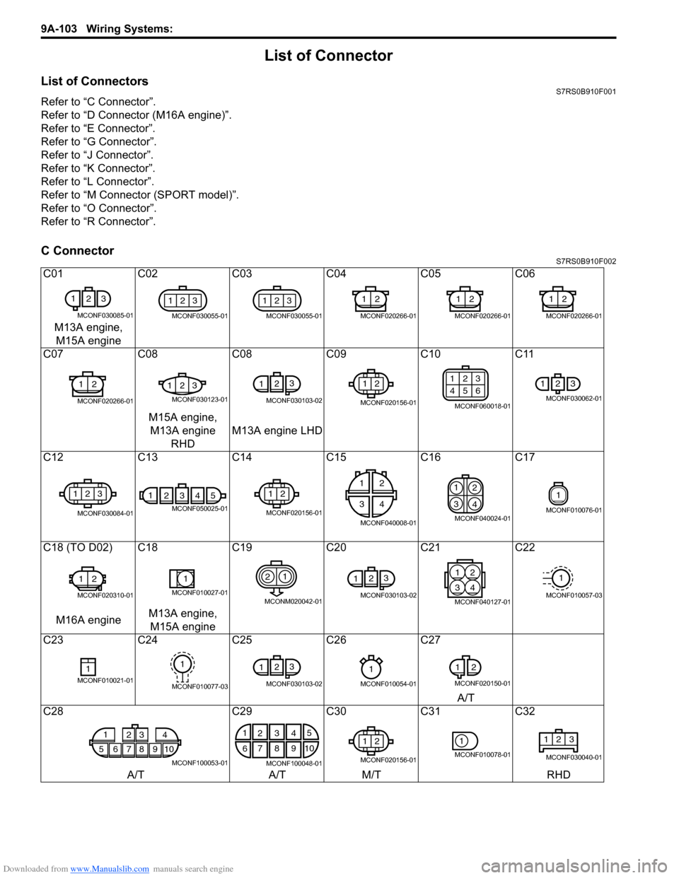
List of Connector
List of ConnectorsS7RS0B910F001
Refer to “C Connector”.
Refer to “D Connector (M16A engine)”.
Refer to “E Connector”.
Refer to “G Connector”.
Refer to “J Connector”.
Refer to “K Connector”.
Refer to “L Connector”.
Refer to “M Connector (SPORT model)”.
Refer to “O Connector”.
Refer to “R Connector”.
C ConnectorS7RS0B910F002
C01C02C03 C04 C05 C06
M13A engine, M15A engine
C07 C08C08 C09 C10 C11
M15A engine, M13A engine RHD M13A engine LHD
C12 C13C14 C15 C16 C17
C18 (TO D02) C18 C19C20C21C22
M16A engine M13A engine,
M15A engine
C23 C24C25 C26 C27
A/T
C28 C29C30C31C32
A/T A/TM/T RHD
1
23
MCONF030085-01
123
MCONF030055-01
123
MCONF030055-01
12
MCONF020266-01
12
MCONF020266-01
12
MCONF020266-01
12
MCONF020266-01
123
MCONF030123-01
123
MCONF030103-02
12
MCONF020156-01
123
456
MCONF060018-01
123
MCONF030062-01
123
MCONF030084-01
14325
MCONF050025-01
12
MCONF020156-01
12
34
MCONF040008-01
1
2
3 4
MCONF040024-01
1
MCONF010076-01
12
MCONF020310-01
1
MCONF010027-01
21
MCONM020042-01
12
3
MCONF030103-02
21
43
MCONF040127-01
1
MCONF010057-03
1MCONF010021-01
1
MCONF010077-03
123
MCONF030103-02
1
MCONF010054-01
1
2
MCONF020150-01
1
5678910 23 4
MCONF100053-01
1
2 5
6 7
103
84
9
MCONF100048-01
12
MCONF020156-01
1
MCONF010078-01
123
MCONF030040-01