C23 SUZUKI SWIFT 2007 2.G Service Workshop Manual
[x] Cancel search | Manufacturer: SUZUKI, Model Year: 2007, Model line: SWIFT, Model: SUZUKI SWIFT 2007 2.GPages: 1496, PDF Size: 34.44 MB
Page 455 of 1496
Downloaded from www.Manualslib.com manuals search engine Rear Suspension: 2C-1
Suspension
Rear Suspension
General Description
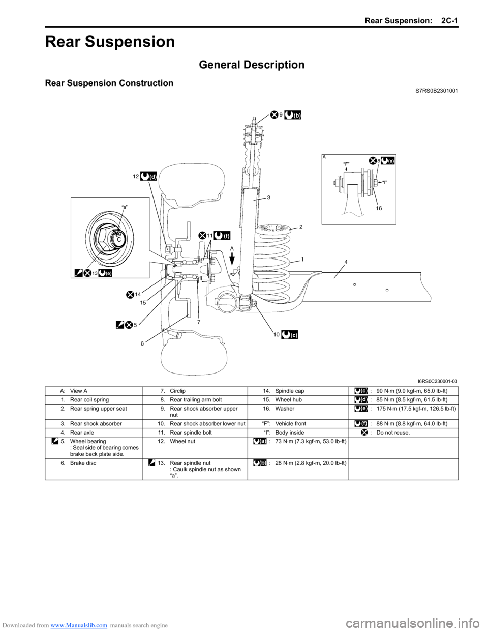
Rear Suspension ConstructionS7RS0B2301001
I6RS0C230001-03
A: View A7. Circlip 14. Spindle cap : 90 N⋅m (9.0 kgf-m, 65.0 lb-ft)
1. Rear coil spring 8. Rear trailing arm bolt 15. Wheel hub : 85 N⋅m (8.5 kgf-m, 61.5 lb-ft)
2. Rear spring upper seat 9. Rear shock absorber upper
nut 16. Washer
: 175 N⋅m (17.5 kgf-m, 126.5 lb-ft)
3. Rear shock absorber 10. Rear shock absorber lower nut “F”: Vehicle front : 88 N⋅m (8.8 kgf-m, 64.0 lb-ft)
4. Rear axle 11. Rear spindle bolt “I”: Body inside : Do not reuse.
5. Wheel bearing : Seal side of bearing comes
brake back plate side. 12. Wheel nut
: 73 N⋅m (7.3 kgf-m, 53.0 lb-ft)
6. Brake disc 13. Rear spindle nut
: Caulk spindle nut as shown
“a”. :28 N
⋅m (2.8 kgf-m, 20.0 lb-ft)
Page 456 of 1496
Downloaded from www.Manualslib.com manuals search engine 2C-2 Rear Suspension:
Repair Instructions
Rear Wheel Alignment InspectionS7RS0B2306017
Measure toe and camber referring to “Front Wheel
Alignment Inspection and Adjustment in Section 2B”.
NOTE
Rear suspension is not adjustable structure.
Rear toe (total)
: IN 3.8 ± 3.8 mm (IN 0.1969 ± 0.1969 in)
Rear camber
: –1 ° ± 1
If measured value is out of specified value, check
following items for damage, deformation and crack.
• Rear axle (torsion beam)
• Spindle, wheel hub or wheel bearing
• Vehicle body
Rear Shock Absorber Removal and InstallationS7RS0B2306001
Removal 1) Hoist vehicle and remove rear wheels.
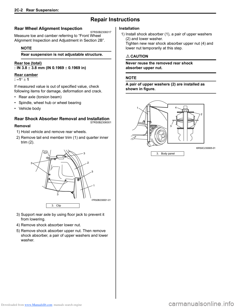
2) Remove tail end member trim (1) and quarter inner trim (2).
3) Support rear axle by using floor jack to prevent it from lowering.
4) Remove shock absorber lower nut.
5) Remove shock absorber upper nut. Then remove shock absorber, a pair of upper washers and lower
washer. Installation
1) Install shock absorber (1), a pair of upper washers (2) and lower washer.
Tighten new rear shock absorber upper nut (4) and
lower nut temporarily at this step.
CAUTION!
Never reuse the removed rear shock
absorber upper nut.
NOTE
A pair of upper washers (2) are installed as
shown in figure.
3. Clip
3
3 2
3
1
3
I7RS0B230001-01
3. Body panel
14
3 2
I6RS0C230005-01
Page 458 of 1496
Downloaded from www.Manualslib.com manuals search engine 2C-4 Rear Suspension:
Rear Shock Absorber Bush Removal and
Installation
S7RS0B2306003
Removal1) Remove rear shock absorber referring to “Rear Shock Absorber Remova l and Installation”.
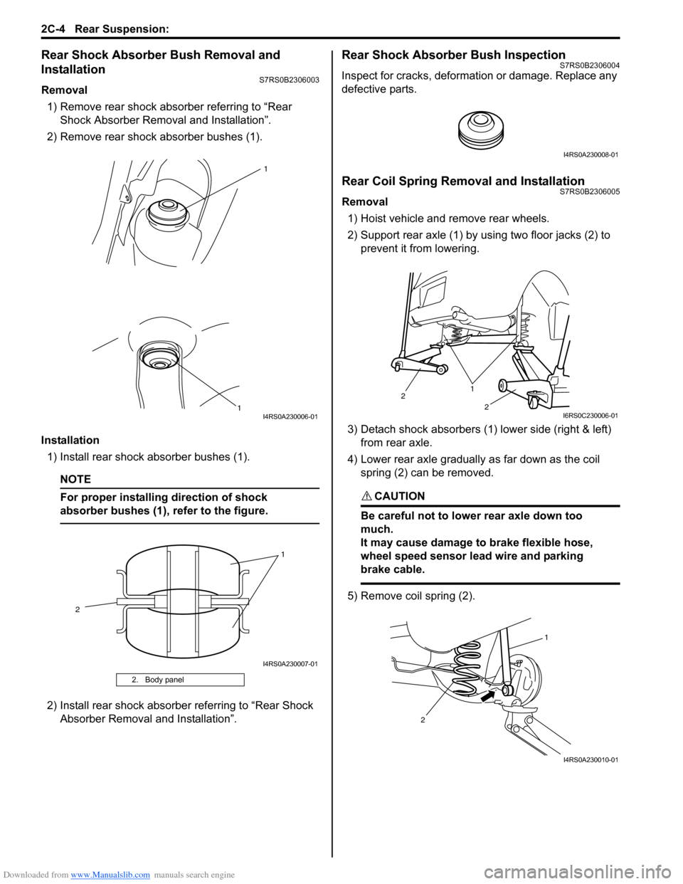
2) Remove rear shock absorber bushes (1).
Installation 1) Install rear shock absorber bushes (1).
NOTE
For proper installing direction of shock
absorber bushes (1), refer to the figure.
2) Install rear shock absorber referring to “Rear Shock Absorber Removal and Installation”.
Rear Shock Absorber Bush InspectionS7RS0B2306004
Inspect for cracks, deformation or damage. Replace any
defective parts.
Rear Coil Spring Removal and InstallationS7RS0B2306005
Removal
1) Hoist vehicle and remove rear wheels.
2) Support rear axle (1) by using two floor jacks (2) to prevent it from lowering.
3) Detach shock absorbers (1) lower side (right & left) from rear axle.
4) Lower rear axle gradually as far down as the coil spring (2) can be removed.
CAUTION!
Be careful not to lowe r rear axle down too
much.
It may cause damage to brake flexible hose,
wheel speed sensor lead wire and parking
brake cable.
5) Remove coil spring (2).
2. Body panel
1
1
I4RS0A230006-01
1
2
I4RS0A230007-01
I4RS0A230008-01
1
2
2
I6RS0C230006-01
1
2
I4RS0A230010-01
Page 464 of 1496
Downloaded from www.Manualslib.com manuals search engine 2C-10 Rear Suspension:
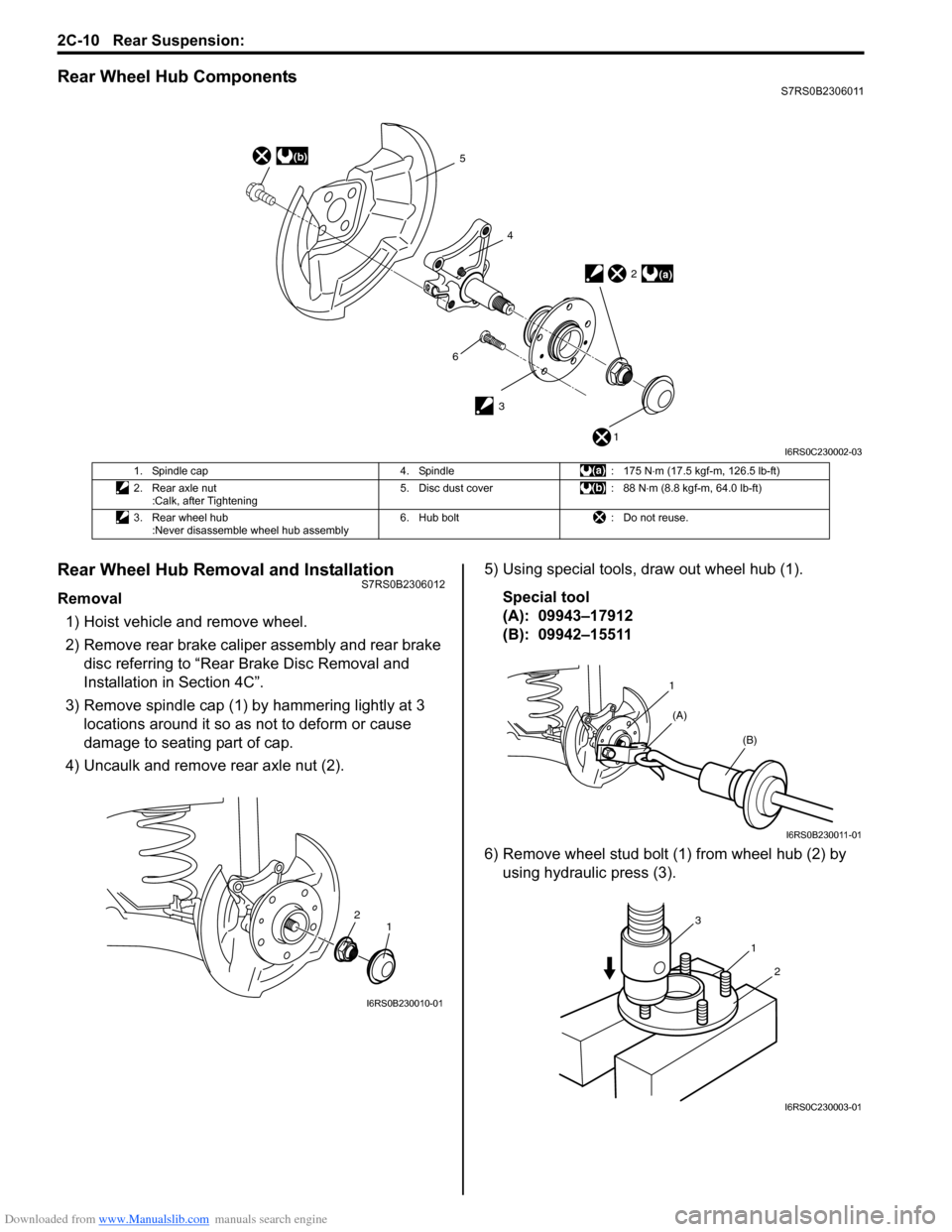
Rear Wheel Hub ComponentsS7RS0B2306011
Rear Wheel Hub Removal and InstallationS7RS0B2306012
Removal1) Hoist vehicle and remove wheel.
2) Remove rear brake caliper assembly and rear brake disc referring to “Rear Brake Disc Removal and
Installation in Section 4C”.
3) Remove spindle cap (1) by hammering lightly at 3 locations around it so as not to deform or cause
damage to seating part of cap.
4) Uncaulk and remove rear axle nut (2). 5) Using special tools, draw out wheel hub (1).
Special tool
(A): 09943–17912
(B): 09942–15511
6) Remove wheel stud bolt (1) from wheel hub (2) by using hydraulic press (3).
(b)5
4
3
(a)2
1
6
I6RS0C230002-03
1. Spindle cap 4. Spindle: 175 N⋅m (17.5 kgf-m, 126.5 lb-ft)
2. Rear axle nut :Calk, after Tightening 5. Disc dust cover
: 88 N⋅m (8.8 kgf-m, 64.0 lb-ft)
3. Rear wheel hub :Never disassemble wheel hub assembly 6. Hub bolt
: Do not reuse.
2
1
I6RS0B230010-01
1
(A) (B)
I6RS0B230011-01
1
3
2
I6RS0C230003-01
Page 465 of 1496
Downloaded from www.Manualslib.com manuals search engine Rear Suspension: 2C-11
Installation
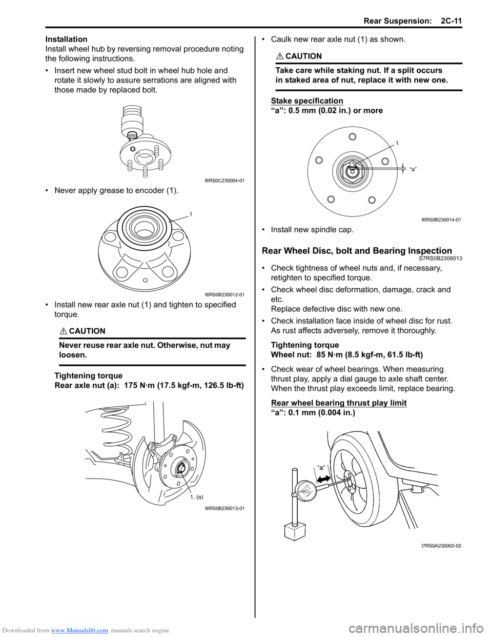
Install wheel hub by reversing removal procedure noting
the following instructions.
• Insert new wheel stud bolt in wheel hub hole and rotate it slowly to assure serrations are aligned with
those made by replaced bolt.
• Never apply grease to encoder (1).
• Install new rear axle nut (1) and tighten to specified torque.
CAUTION!
Never reuse rear axle nut. Otherwise, nut may
loosen.
Tightening torque
Rear axle nut (a): 175 N·m (17.5 kgf-m, 126.5 lb-ft) • Caulk new rear axle nut (1) as shown.
CAUTION!
Take care while staking nut. If a split occurs
in staked area of nut,
replace it with new one.
Stake specification
“a”: 0.5 mm (0.02 in.) or more
• Install new spindle cap.
Rear Wheel Disc, bolt and Bearing InspectionS7RS0B2306013
• Check tightness of wheel nuts and, if necessary, retighten to specified torque.
• Check wheel disc deformation, damage, crack and etc.
Replace defective disc with new one.
• Check installation face insi de of wheel disc for rust.
As rust affects adversely, remove it thoroughly.
Tightening torque
Wheel nut: 85 N·m (8.5 kgf-m, 61.5 lb-ft)
• Check wear of wheel bearings. When measuring thrust play, apply a dial gauge to axle shaft center.
When the thrust play exce eds limit, replace bearing.
Rear wheel bearing thrust play
limit
“a”: 0.1 mm (0.004 in.)
I6RS0C230004-01
1
I6RS0B230012-01
1, (a)
I6RS0B230013-01
1
“a”
I6RS0B230014-01
I7RS0A230002-02
Page 1181 of 1496
Downloaded from www.Manualslib.com manuals search engine Wiring Systems: 9A-10
Connector Layout Diagram
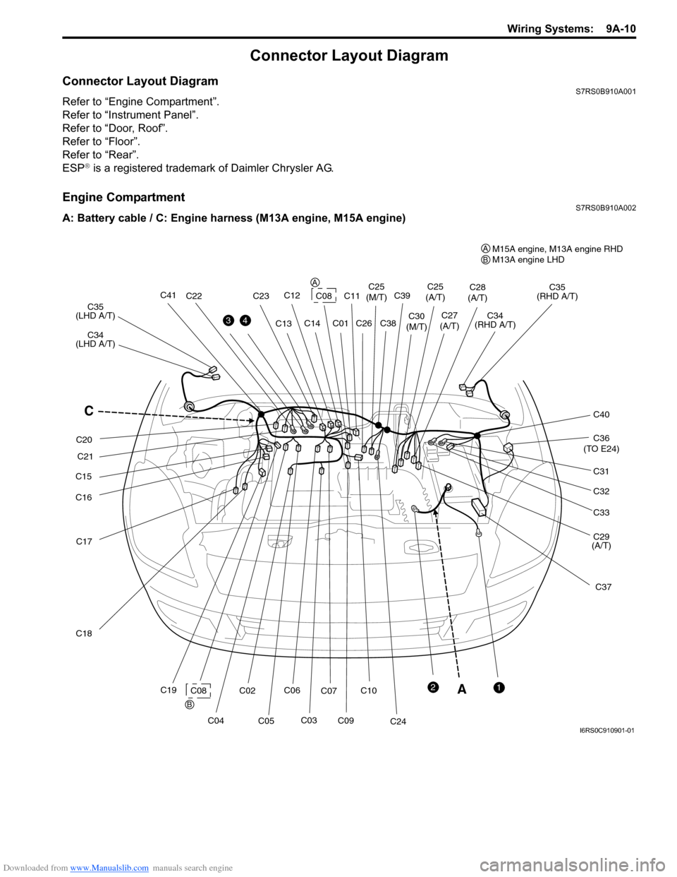
Connector Layout DiagramS7RS0B910A001
Refer to “Engine Compartment”.
Refer to “Instrument Panel”.
Refer to “Door, Roof”.
Refer to “Floor”.
Refer to “Rear”.
ESP
® is a registered trademark of Daimler Chrysler AG.
Engine CompartmentS7RS0B910A002
A: Battery cable / C: Engine harness (M13A engine, M15A engine)
A
C36
(TO E24)
C17
C18
C19 C35
(RHD A/T)
C34
(LHD A/T) C35
(LHD A/T) C34
(RHD A/T)
C37
C15
C16
C02C08
C03
C10
C0912
34
C31
C32
C33
C29
(A/T)
C28
(A/T)
C27
(A/T)C30
(M/T) C25
(A/T)
C24
C25
(M/T)
C26
C07
C06
C05
C04
C22
C21
C20 C23
C13
C12C14
C08
C01
CC40
C41C39
C38C11
A
A
B
BM15A engine, M13A engine RHD
M13A engine LHD
I6RS0C910901-01
Page 1182 of 1496

Downloaded from www.Manualslib.com manuals search engine 9A-11 Wiring Systems:
C: Engine harnessNo./Color Connective position No./Color Connective positionC01/GRY IAC valve C22/- Generator #2
C02/GRY IG Coil #1 C23/BLK Starting motor #1
C03/GRY IG Coil #2 C24/- Starting motor #2
C04/GRY Fuel injector #1 C25/GR Y VSS (Vehicle speed sensor)
C05/GRY Fuel injector #2 C26/GRY Knock sensor
C06/GRY Fuel injector #3 C27/BLU (A/
T) Input shaft speed sensor
C07/GRY Fuel injector #4 C28/GRY
(A/T) Trans axle range sensor
C08/BLK or GRY CMP sensor C29/GRY
(A/T) Shift solenoid
C09/BLK ECT sensor C30/BLK
(M/T) Back-up light switch
C10/GRY EGR stepper motor C31/- Main fuse box C11/BLK Throttle position sensor C32/GRY
(IF EQPD) Current sensor
C12/BLK MAP sensor C33/- Main fuse box
C13/BLK MAF sensor C34/N (A/T) TCM
C14/BLK EVAP canister purge valve C35/N (A/T) TCM
C15/GRY Heated oxygen sensor #1 C36/N Main harness (To E24)
C16/GRN Heated oxygen sensor #2 C37/GRY ECM C17/BLK A/C compressor C38/- Weld splice C18/N Oil pressure switch C39/- Weld splice
C19/BLU VVT solenoid C40/- Weld splice
C20/GRY CKP sensor C41/- Weld splice
C21/GRY or BLK Generator #1
Page 1183 of 1496
Downloaded from www.Manualslib.com manuals search engine Wiring Systems: 9A-12
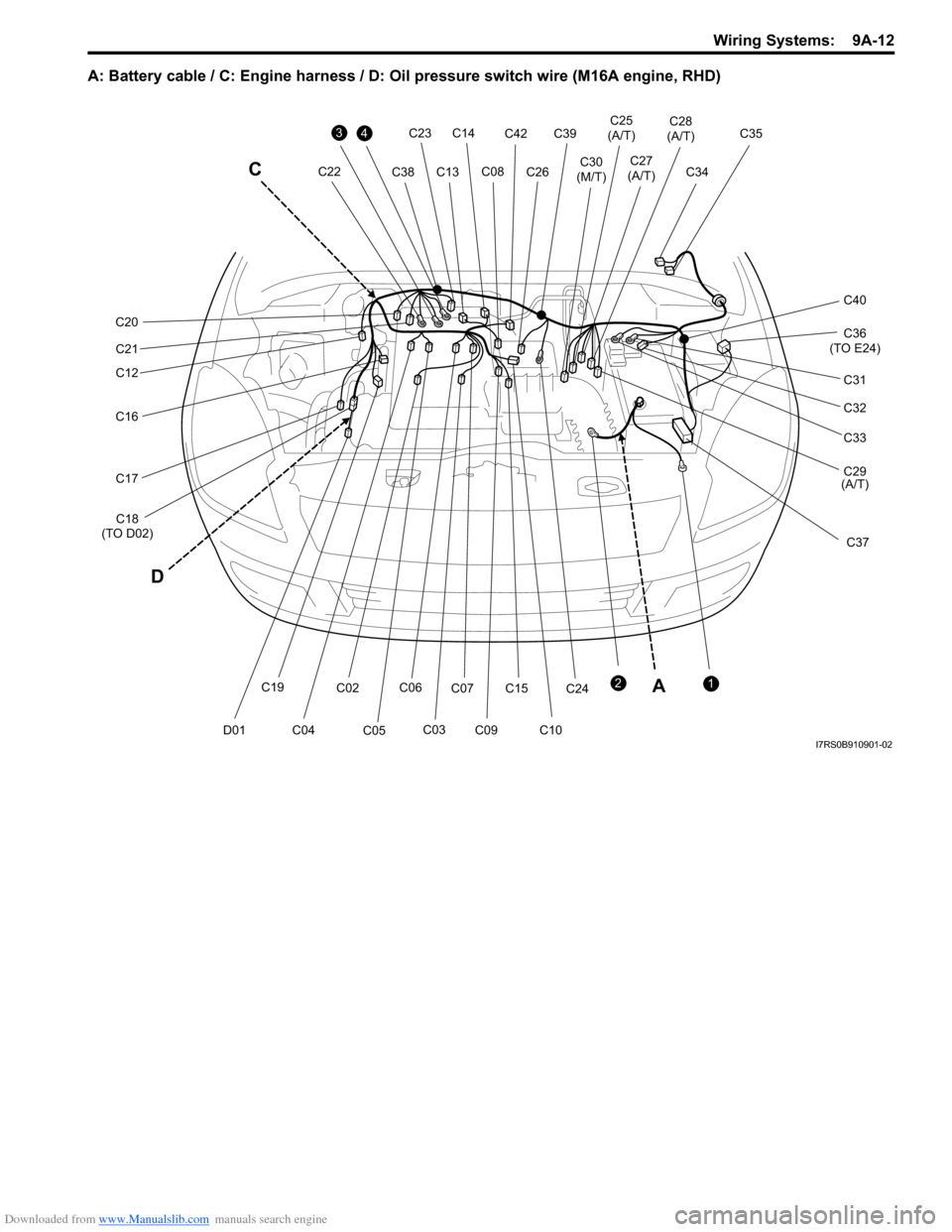
A: Battery cable / C: Engine harness / D: Oil pressure switch wire (M16A engine, RHD)
C36
(TO E24)
C35
C34
C37
34
C31
C32
C33
C29
(A/T)
C28
(A/T)
C27
(A/T)C30
(M/T) C25
(A/T)C26C22 C23C13C38
C14
C08
C40
C39
C42
A
C17
C18
(TO D02)
C19
C16
C02
C03C10
C09
12C24C07C15
C06
C05
C04D01
C21
C12
C20
C
D
I7RS0B910901-02
Page 1184 of 1496

Downloaded from www.Manualslib.com manuals search engine 9A-13 Wiring Systems:
C: Engine harness
D: Oil pressure switch wireNo./Color Connective position No./Color Connective position
C02/GRY IG Coil #1 C24/- Starting motor #2
C03/GRY IG Coil #2 C23/BLK Starting motor #1
C04/GRY Fuel injector #1 C25/GRY
(A/T) VSS (Vehicle speed sensor)
C05/GRY Fuel injector #2 C26/GRY Knock shaft speed sensor
C06/GRY Fuel injector #3 C27/BLU (A/
T) Input shaft speed sensor
C07/GRY Fuel injector #4 C28/GRY
(A/T) Trans axle range sensor
C08/BLK CMP sensor C29/GRY
(A/T) Shift solenoid
C09/BLK ECT sensor C30/BLK
(M/T) Back-up light switch
C10/GRY EGR stepper motor C31/- Main fuse box C12/BLK MAP sensor C32/GRY Current sensor
C13/BLK MAF sensor C33/- Main fuse box
C14/BLK EVAP canister purge valve C34/N (A/T) TCM
C15/BLK Heated oxygen sensor #1 C35/N (A/T) TCM
C16/GRN Heated oxygen sensor #2 C36/N Main harness (To E24) C17/BLK A/C compressor C37/GRY ECM C18/N Oil pressure switch wire (To D02) C38/- Weld splice
C19/BLU VVT solenoid C39/- Weld splice
C20/GRY CKP sensor C40/- Weld splice C21/BLK Generator #1 C42/BLK Electric throttle body C22/- Generator #2
No./Color Connective position No./ColorConnective position
D01/N Oil pressure switch D02/GRY Engine harness (To C18)
Page 1217 of 1496
Downloaded from www.Manualslib.com manuals search engine Wiring Systems: 9A-46
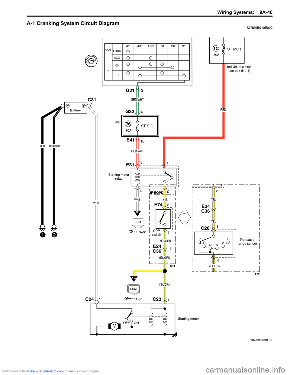
A-1 Cranking System Circuit DiagramS7RS0B910E002
Starting motorrelay
W
"A-5"
ECM
P
R N D2LTransaxle
range sensor
C28
E741
4
E31
C231C241
Starting motor
MOFF ON
BLK
1
BLK/GRY
C311
Battery
E24
C361
RED
Individual circuit
fuse box (No.1)
10
30A
36
10A
WHTWHT
M/T
IF EQPD
E24
C361
J/B
A/T
E4110
13
2
4
RED/WHT
2 ST MOT
ST SIG
YEL/GRN
YG
"A-5"
ECM
GRN/WHT
G212
YEL/GRN
YEL/GRN
YEL
YEL/GRN
YEL
YEL
G324
+B1
LOCK
ACC
ON
ST ACC IG1 IG2
STOUT
IN
+B2
21CPP
switch
2
I7RS0B910940-01