COWL TOP COMP SUZUKI SWIFT 2007 2.G Service Workshop Manual
[x] Cancel search | Manufacturer: SUZUKI, Model Year: 2007, Model line: SWIFT, Model: SUZUKI SWIFT 2007 2.GPages: 1496, PDF Size: 34.44 MB
Page 299 of 1496
Downloaded from www.Manualslib.com manuals search engine Engine Mechanical: 1D-14
Throttle Body CleaningS7RS0B1406008
Clean electric throttle body assembly referring to
“Throttle Valve Visual Check” under “Electric Throttle
Body Assembly On-Vehicle Inspection in Section 1C”.
Intake Manifold Removal and InstallationS7RS0B1406009
Removal1) Remove cowl top plate referring to “Cowl Top Components in Section 9K”.
2) Remove throttle body referring to “Electric Throttle Body Assembly Removal and Installation”.
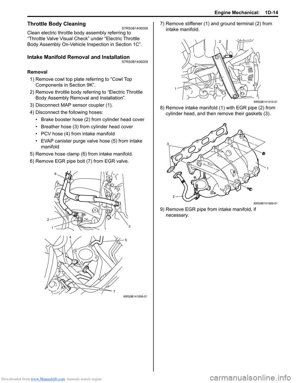
3) Disconnect MAP sensor coupler (1).
4) Disconnect the following hoses: • Brake booster hose (2) from cylinder head cover
• Breather hose (3) from cylinder head cover
• PCV hose (4) from intake manifold
• EVAP canister purge valve hose (5) from intake manifold
5) Remove hose clamp (6) from intake manifold.
6) Remove EGR pipe bolt (7) from EGR valve. 7) Remove stiffener (1) and ground terminal (2) from
intake manifold.
8) Remove intake manifold (1) with EGR pipe (2) from
cylinder head, and then remove their gaskets (3).
9) Remove EGR pipe from intake manifold, if necessary.
6
2 1
3
54
7I6RS0B141008-01
1
2
I6RS0B141010-01
3
2
1
I6RS0B141009-01
Page 300 of 1496
Downloaded from www.Manualslib.com manuals search engine 1D-15 Engine Mechanical:
Installation
Reverse removal procedure for installation noting the
followings.
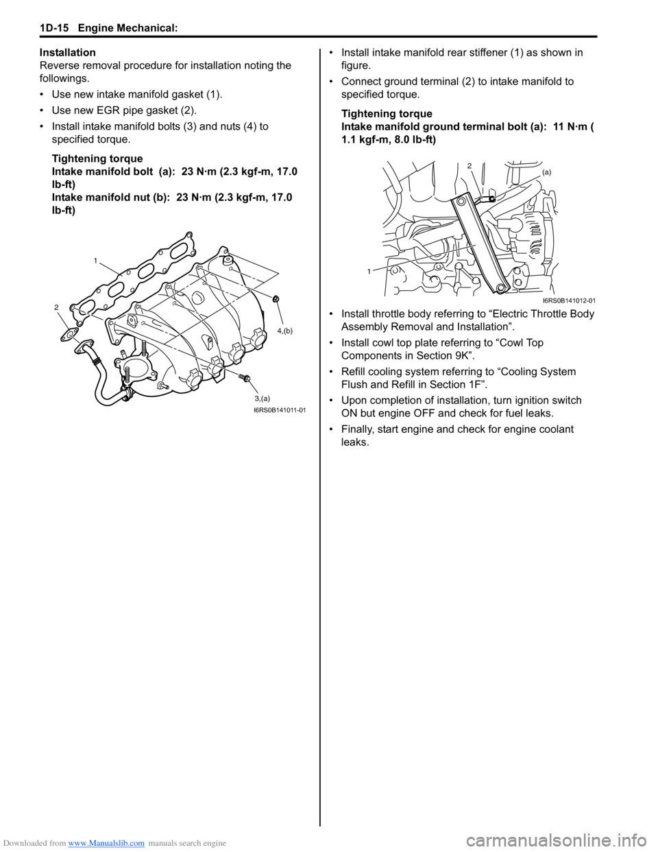
• Use new intake manifold gasket (1).
• Use new EGR pipe gasket (2).
• Install intake manifold bolts (3) and nuts (4) to specified torque.
Tightening torque
Intake manifold bolt (a): 23 N·m (2.3 kgf-m, 17.0
lb-ft)
Intake manifold nut (b): 23 N·m (2.3 kgf-m, 17.0
lb-ft) • Install intake manifold rear stiffener (1) as shown in
figure.
• Connect ground terminal (2) to intake manifold to specified torque.
Tightening torque
Intake manifold ground terminal bolt (a): 11 N·m (
1.1 kgf-m, 8.0 lb-ft)
• Install throttle body referrin g to “Electric Throttle Body
Assembly Removal and Installation”.
• Install cowl top plate referring to “Cowl Top Components in Section 9K”.
• Refill cooling system refe rring to “Cooling System
Flush and Refill in Section 1F”.
• Upon completion of installation, turn ignition switch ON but engine OFF and check for fuel leaks.
• Finally, start engine and check for engine coolant leaks.
1
2
3,(a)
4,(b)
I6RS0B141011-01
(a)
12
I6RS0B141012-01
Page 302 of 1496

Downloaded from www.Manualslib.com manuals search engine 1D-17 Engine Mechanical:
Engine Assembly Removal and InstallationS7RS0B1406011
NOTE
After replacing electric throttle body
assembly, perform calibration of throttle
valve referring to “Electric Throttle Body
System Calibration in Section 1C”.
Removal1) Relieve fuel pressure according to “Fuel Pressure Relief Procedure in Section 1G”.
2) Disconnect negative and pos itive cable at battery.
3) Remove battery and tray.
4) Remove engine hood after disconnecting windshield washer hose.
5) Remove right and left side engine under covers.
6) Remove A/C compressor belt by referring to “Compressor Drive Belt Remo val and Installation in
Section 7B” or “Compressor Drive Belt Removal and
Installation in Section 7B”.
7) Drain engine oil, transaxle oil and coolant.
8) Remove cowl top plate referring to “Cowl Top Components in Section 9K”.
9) Remove air cleaner assembly referring to “Air Cleaner Components”.
10) With hose connected, detach A/C compressor from its bracket (A/C model) referring to “Compressor
Assembly Removal and Installation in Section 7B” or
“Compressor Assembly Removal and Installation in
Section 7B”.
CAUTION!
Suspend removed A/C compressor at a place
where no damage will be caused during
removal and installation of engine assembly.
11) Remove intake manifold rear stiffener (1) from intake manifold and cylinder block. 12) Disconnect the following electric wires:
• MAP sensor (1)
• ECT sensor (2)
•EGR valve (3)
• CMP sensor (4)
• Electric throttle body assembly (5)
• Ignition coil assembly (6)
• Injectors (7)
• Heated oxygen sensor No. 2 (8) and No. 1 (9)
• Oil control valve (10)
• Engine oil pressure switch (11)
• CKP sensor (12)
• Knock sensor (13)
• Back up light switch (14)
• Generator (15)
• Starting motor (16)
• Ground terminal (17) from intake manifold
• Battery ground terminal (18) from exhaust manifold
• Battery ground cable (19) from transaxle
• Magnet clutch switch of A/C compressor (A/C model)
• Each wire harness clamps
• Output shaft speed sensor (VSS) (34) (A/T model)
• Solenoid valve (33) (A/T model)
• Transmission range sensor (32) (A/T model)
• Input shaft speed sensor (31) (A/T model)
13) Remove fuse box from its bracket.
14) Disconnect the following cables: • Gear select control cable (23) (M/T model)
• Gear shift control cable (24) (M/T model)
• A/T select cable (A/T model)
15) Disconnect the following hoses: • Brake booster hose (26) from intake manifold
• Radiator inlet and outlet hoses (20) from each pipe
• Heater inlet and outlet hoses (21) from each pipe
• Fuel feed hoses (22) from fuel feed pipe
• EVAP canister purge valve hose (30) from purge pipe
• A/T fluid cooler hoses (A/T model)
16) With hose connected, detach clutch operating cylinder (25). (M/T model)
CAUTION!
Suspend removed clutch operating cylinder
at a place where no damage will be caused
during removal and installation of engine
assembly.
1
I6RS0B141014-01
Page 304 of 1496
Downloaded from www.Manualslib.com manuals search engine 1D-19 Engine Mechanical:
24) Before removing engine with transaxle from engine compartment, recheck to make sure all hoses,
electric wires and cables are disconnected from
engine and transaxle.
25) Lower engine with transaxle from engine compartment.
CAUTION!
Before lowering engine, to avoid damage to
A/C compressor and clutch operating
cylinder, make clearance by rising them. Be
sure not to damage suspended A/C
compressor and clutch operating cylinder.
26) Disconnect transaxle from engine, referring to “Manual Transaxle Unit Dismounting and
Remounting in Section 5B” or “Automatic Transaxle
Unit Dismounting and Re mounting in Section 5A”.
27) For M/T model, remove clutch cover and clutch disk referring to “Clutch Cover, Clutch Disc and Flywheel
Removal and Installa tion in Section 5C”.
Installation 1) For M/T model, install clutch cover and clutch disk referring to “Clutch Cover, Clutch Disc and Flywheel
Removal and Installa tion in Section 5C”.
2) Connect transaxle to engine referring to “Manual Transaxle Unit Dismounting and Remounting in
Section 5B” or “Automatic Transaxle Unit
Dismounting and Remounting in Section 5A”.
3) Lift engine and transaxle into engine compartment with jack.
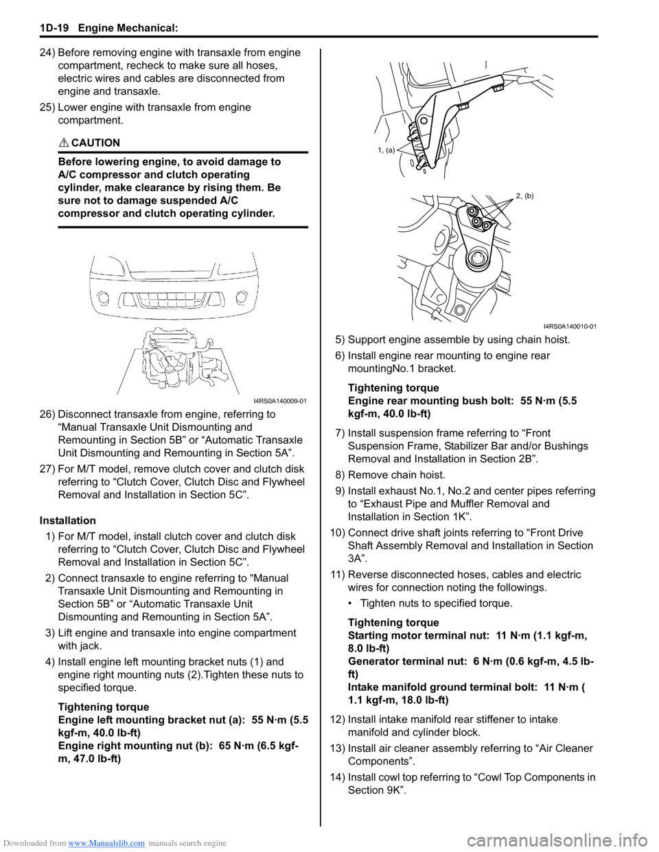
4) Install engine left mounting bracket nuts (1) and engine right mounting nuts (2).Tighten these nuts to
specified torque.
Tightening torque
Engine left mounting bracket nut (a): 55 N·m (5.5
kgf-m, 40.0 lb-ft)
Engine right mounting nut (b): 65 N·m (6.5 kgf-
m, 47.0 lb-ft) 5) Support engine assemble by using chain hoist.
6) Install engine rear mounting to engine rear
mountingNo.1 bracket.
Tightening torque
Engine rear mounting bush bolt: 55 N·m (5.5
kgf-m, 40.0 lb-ft)
7) Install suspension frame referring to “Front Suspension Frame, Stabiliz er Bar and/or Bushings
Removal and Installati on in Section 2B”.
8) Remove chain hoist.
9) Install exhaust No.1, No.2 and center pipes referring to “Exhaust Pipe and Muffler Removal and
Installation in Section 1K”.
10) Connect drive shaft joints referring to “Front Drive Shaft Assembly Removal and Installation in Section
3A”.
11) Reverse disconnected hoses, cables and electric wires for connection noting the followings.
• Tighten nuts to specified torque.
Tightening torque
Starting motor terminal nut: 11 N·m (1.1 kgf-m,
8.0 lb-ft)
Generator terminal nut: 6 N·m (0.6 kgf-m, 4.5 lb-
ft)
Intake manifold ground terminal bolt: 11 N·m (
1.1 kgf-m, 18.0 lb-ft)
12) Install intake manifold rear stiffener to intake
manifold and cylinder block.
13) Install air cleaner assembly referring to “Air Cleaner Components”.
14) Install cowl top referring to “Cowl Top Components in
Section 9K”.
I4RS0A140009-01
1, (a)
2, (b)
I4RS0A140010-01
Page 437 of 1496
Downloaded from www.Manualslib.com manuals search engine Front Suspension: 2B-4
Reference Information
Side slip
When checked with side slip tester, side slip should
satisfy following specification.Side slip
0 to IN 3.0 mm/m (0 to IN 0.118 in/3.3 ft)
If side slip is greatly di
fferent, toe or front wheel
alignment may not be correct.
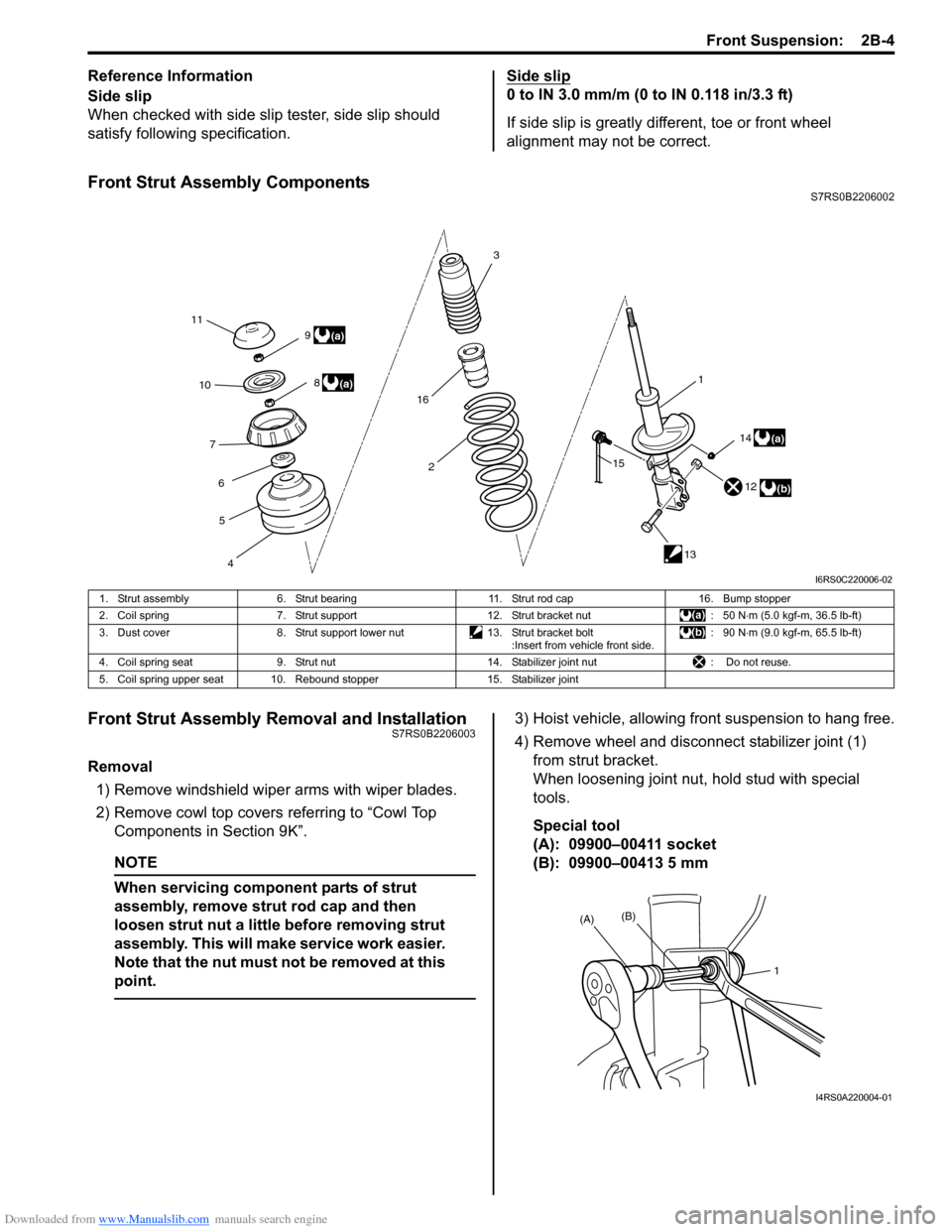
Front Strut Assembly ComponentsS7RS0B2206002
Front Strut Assembly Removal and InstallationS7RS0B2206003
Removal
1) Remove windshield wipe r arms with wiper blades.
2) Remove cowl top covers referring to “Cowl Top
Components in Section 9K”.
NOTE
When servicing component parts of strut
assembly, remove stru t rod cap and then
loosen strut nut a little before removing strut
assembly. This will make service work easier.
Note that the nut must not be removed at this
point.
3) Hoist vehicle, allowing front suspension to hang free.
4) Remove wheel and disconn ect stabilizer joint (1)
from strut bracket.
When loosening joint nu t, hold stud with special
tools.
Special tool
(A): 09900–00411 socket
(B): 09900–00413 5 mm
11 3
2 1
12
13
4
5
6
7
10
8(a)
(b)
9
(a)
14
15(a)
16
I6RS0C220006-02
1. Strut assembly
6. Strut bearing 11. Strut rod cap16. Bump stopper
2. Coil spring 7. Strut support 12. Strut bracket nut : 50 N⋅m (5.0 kgf-m, 36.5 lb-ft)
3. Dust cover 8. Strut support lower nut 13. Strut bracket bolt
:Insert from vehicle front side. : 90 N
⋅m (9.0 kgf-m, 65.5 lb-ft)
4. Coil spring seat 9. Strut nut 14. Stabilizer joint nut : Do not reuse.
5. Coil spring upper seat 10. Rebound stopper 15. Stabilizer joint
1
(A)
(B)
I4RS0A220004-01
Page 511 of 1496
Downloaded from www.Manualslib.com manuals search engine Brake Control System and Diagnosis: 4A-13
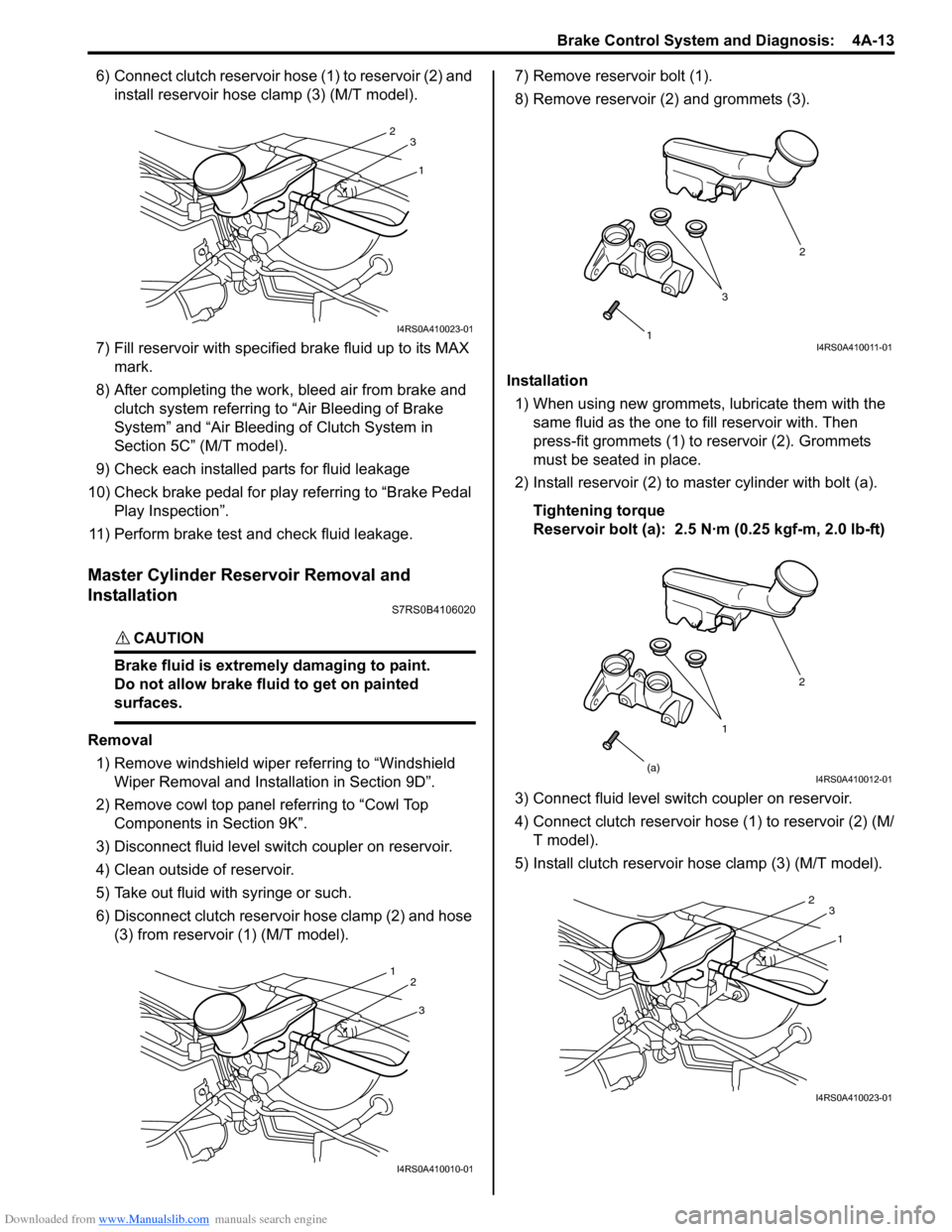
6) Connect clutch reservoir hose (1) to reservoir (2) and install reservoir hose clamp (3) (M/T model).
7) Fill reservoir with specified brake fluid up to its MAX
mark.
8) After completing the work, bleed air from brake and clutch system referring to “Air Bleeding of Brake
System” and “Air Bleeding of Clutch System in
Section 5C” (M/T model).
9) Check each installed parts for fluid leakage
10) Check brake pedal for play referring to “Brake Pedal Play Inspection”.
11) Perform brake test and check fluid leakage.
Master Cylinder Reservoir Removal and
Installation
S7RS0B4106020
CAUTION!
Brake fluid is extremely damaging to paint.
Do not allow brake fluid to get on painted
surfaces.
Removal 1) Remove windshield wiper referring to “Windshield Wiper Removal and Insta llation in Section 9D”.
2) Remove cowl top panel referring to “Cowl Top Components in Section 9K”.
3) Disconnect fluid level s witch coupler on reservoir.
4) Clean outside of reservoir.
5) Take out fluid with syringe or such.
6) Disconnect clutch reservoir hose clamp (2) and hose (3) from reservoir (1) (M/T model). 7) Remove reservoir bolt (1).
8) Remove reservoir (2) and grommets (3).
Installation 1) When using new grommets, lubricate them with the same fluid as the one to fill reservoir with. Then
press-fit grommets (1) to reservoir (2). Grommets
must be seated in place.
2) Install reservoir (2) to master cylinder with bolt (a).
Tightening torque
Reservoir bolt (a): 2.5 N·m (0.25 kgf-m, 2.0 lb-ft)
3) Connect fluid level switch coupler on reservoir.
4) Connect clutch reservoir hose (1) to reservoir (2) (M/ T model).
5) Install clutch reservoir hose clamp (3) (M/T model).
1
2
3
I4RS0A410023-01
3
1
2
I4RS0A410010-01
1 2
3I4RS0A410011-01
1 2
(a)
I4RS0A410012-01
1
2
3
I4RS0A410023-01
Page 512 of 1496
Downloaded from www.Manualslib.com manuals search engine 4A-14 Brake Control System and Diagnosis:
6) Fill reservoir with specified fluid.
7) After completing the work, bleed air from brake and clutch system referring to “Air Bleeding of Brake
System” and “Air Bleeding of Clutch System in
Section 5C” (M/T model).
8) Install cowl top panel referring to “Cowl Top Components in Section 9K”.
9) Install windshield wiper referring to “Windshield
Wiper Removal and Insta llation in Section 9D”.
10) Perform brake test and check each installed part for fluid leakage.
Master Cylinder Assembly Disassembly and
Assembly
S7RS0B4106013
Disassembly
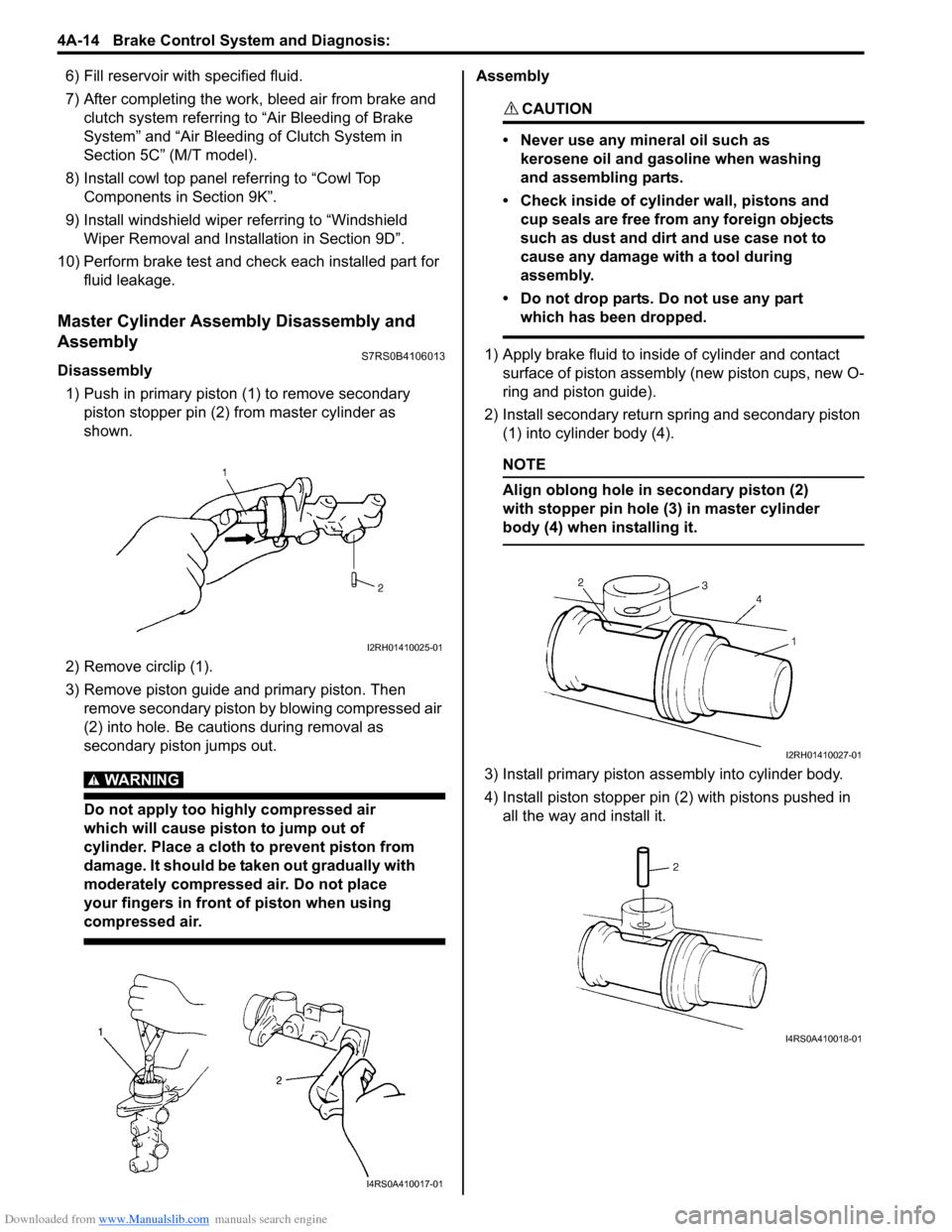
1) Push in primary piston (1) to remove secondary
piston stopper pin (2) from master cylinder as
shown.
2) Remove circlip (1).
3) Remove piston guide and primary piston. Then remove secondary piston by blowing compressed air
(2) into hole. Be cautions during removal as
secondary piston jumps out.
WARNING!
Do not apply too highly compressed air
which will cause piston to jump out of
cylinder. Place a cloth to prevent piston from
damage. It should be taken out gradually with
moderately compressed air. Do not place
your fingers in front of piston when using
compressed air.
Assembly
CAUTION!
• Never use any mineral oil such as kerosene oil and gasoline when washing
and assembling parts.
• Check inside of cylinder wall, pistons and cup seals are free from any foreign objects
such as dust and dirt and use case not to
cause any damage with a tool during
assembly.
• Do not drop parts. Do not use any part which has been dropped.
1) Apply brake fluid to inside of cylinder and contact surface of piston assembly (new piston cups, new O-
ring and piston guide).
2) Install secondary return spring and secondary piston (1) into cylinder body (4).
NOTE
Align oblong hole in secondary piston (2)
with stopper pin hole (3) in master cylinder
body (4) when installing it.
3) Install primary piston assembly into cylinder body.
4) Install piston stopper pin (2) with pistons pushed in all the way and install it.
I2RH01410025-01
I4RS0A410017-01
I2RH01410027-01
I4RS0A410018-01
Page 515 of 1496
Downloaded from www.Manualslib.com manuals search engine Brake Control System and Diagnosis: 4A-17
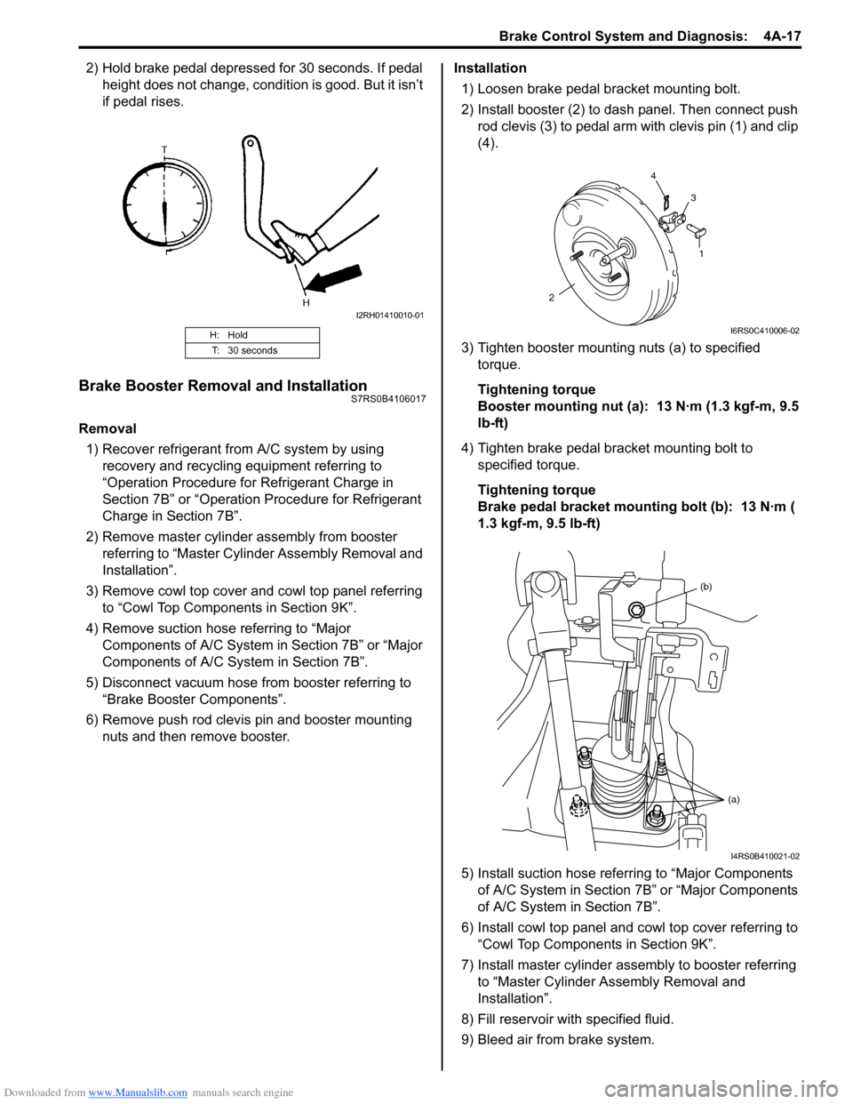
2) Hold brake pedal depressed for 30 seconds. If pedal height does not change, condition is good. But it isn’t
if pedal rises.
Brake Booster Removal and InstallationS7RS0B4106017
Removal
1) Recover refrigerant from A/C system by using recovery and recycling equipment referring to
“Operation Procedure for Refrigerant Charge in
Section 7B” or “Operation Procedure for Refrigerant
Charge in Section 7B”.
2) Remove master cylinder assembly from booster referring to “Master Cylin der Assembly Removal and
Installation”.
3) Remove cowl top cover and cowl top panel referring to “Cowl Top Components in Section 9K”.
4) Remove suction hose referring to “Major Components of A/C System in Section 7B” or “Major
Components of A/C System in Section 7B”.
5) Disconnect vacuum hose from booster referring to “Brake Booster Components”.
6) Remove push rod clevis pin and booster mounting nuts and then remove booster. Installation
1) Loosen brake pedal bracket mounting bolt.
2) Install booster (2) to dash panel. Then connect push rod clevis (3) to pedal arm with clevis pin (1) and clip
(4).
3) Tighten booster mounting nuts (a) to specified torque.
Tightening torque
Booster mounting nut (a): 13 N·m (1.3 kgf-m, 9.5
lb-ft)
4) Tighten brake pedal bracket mounting bolt to specified torque.
Tightening torque
Brake pedal bracket mounting bolt (b): 13 N·m (
1.3 kgf-m, 9.5 lb-ft)
5) Install suction hose referring to “Major Components of A/C System in Section 7B” or “Major Components
of A/C System in Section 7B”.
6) Install cowl top panel and cowl top cover referring to
“Cowl Top Components in Section 9K”.
7) Install master cylinder assembly to booster referring to “Master Cylinder Assembly Removal and
Installation”.
8) Fill reservoir with specified fluid.
9) Bleed air from brake system.
H: Hold
T: 30 seconds
I2RH01410010-01
1
2 4
3
I6RS0C410006-02
(b)
(a)
I4RS0B410021-02
Page 940 of 1496
Downloaded from www.Manualslib.com manuals search engine 7A-4 Heater and Ventilation:
Repair Instructions
HVAC Unit ComponentsS7RS0B7106001
For manual type A/C, refer to “HVAC Unit Components
in Section 7B”.
For automatic type A/C, refer to “HVAC Unit
Components in Section 7B”.
HVAC Unit Removal and InstallationS7RS0B7106002
Removal
1) Disconnect negative (–) cable from battery.
2) Disable air bag system referring to “Disabling Air Bag System in Section 8B”.
3) Remove cowl top panel from vehicle body referring to “Cowl Top Components in Section 9K”.
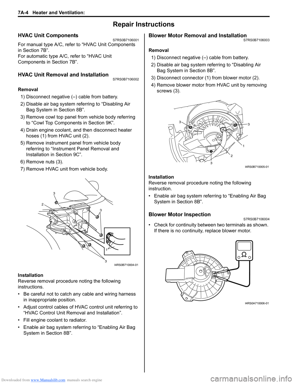
4) Drain engine coolant, and then disconnect heater hoses (1) from HVAC unit (2).
5) Remove instrument panel from vehicle body referring to “Instrument Panel Removal and
Installation in Section 9C”.
6) Remove nuts (3).
7) Remove HVAC unit from vehicle body.
Installation
Reverse removal procedure noting the following
instructions.
• Be careful not to catch any cable and wiring harness in inappropriate position.
• Adjust control cables of HVAC control unit referring to “HVAC Control Unit Remo val and Installation”.
• Fill engine coolant to radiator.
• Enable air bag system referring to “Enabling Air Bag System in Section 8B”.
Blower Motor Removal and InstallationS7RS0B7106003
Removal
1) Disconnect negative (–) cable from battery.
2) Disable air bag system referring to “Disabling Air Bag System in Section 8B”.
3) Disconnect connector (1) from blower motor (2).
4) Remove blower motor from HVAC unit by removing screws (3).
Installation
Reverse removal procedure noting the following
instruction.
• Enable air bag system referring to “Enabling Air Bag System in Section 8B”.
Blower Motor InspectionS7RS0B7106004
• Check for continuity between two terminals as shown. If there is no continuity, replace blower motor.
3
2
3
1
3I4RS0B710004-01
3
1
2
3
3
I4RS0B710005-01
I4RS0A710006-01
Page 972 of 1496

Downloaded from www.Manualslib.com manuals search engine 7B-24 Air Conditioning System: Manual Type
HVAC Unit Removal and InstallationS7RS0B7216006
Removal1) Disconnect negative (–) cable from battery.
2) Disable air bag system referring to “Disabling Air Bag System in Section 8B”.
3) Recover refrigerant from A/C system with recovery and recycling equipment referring to “Recovery” in
“Operation Procedure for Refrigerant Charge”.
4) Remove cowl top panel referring to “Cowl Top Components in Section 9K”.
5) Drain engine coolant, and then disconnect heater hoses (1) from HVAC unit (2).
6) Remove instrument panel from vehicle body referring to “Audio Unit Re moval and Installation in
Section 9C”.
7) Loosen suction hose and liquid pipe bolt (4).
8) Remove nuts (3).
9) Remove HVAC unit from vehicle body. Installation
Reverse removal procedure noting the following
instructions.
• Replenish specified amount of compressor oil to
compressor suction side referring to “Replenishing
Compressor Oil” in “Operation Procedure for
Refrigerant Charge”.
• Install the padding (1) to the installation hole uniformly.
• Evacuate and charge the A/C system referring to “Evacuation” and “Charge” in “Operation Procedure
for Refrigerant Charge”.
• Adjust control cables referr ing to “HVAC Control Unit
Removal and Installati on in Section 7A”.
• Enable air bag system referring to “Enabling Air Bag System in Section 8B”.
Evaporator InspectionS7RS0B7216007
Check the followings.
• Clog of A/C evaporator fins.If any clogs are found, A/C evaporator fins should be
washed with water, and then should be dried with
compressed air.
• A/C evaporator fins for leakage and breakage. If any defects are found, repair or replace A/C
evaporator.
• A/C evaporator fittings for leakage. If any defects are found, repair or replace A/C
evaporator.
2. Blower upper case 8. Temperature control door assembly 14. Temperature control lever 20. Packing
3. Air intake control actuator 9. Blower motor resistor 15. Airflow control lever21. Filter cover (if equipped)
4. HVAC Air filter (if equipped) 10. Blower lower case 16. Evaporator22. Drain hose
5. Heater unit upper case 11. Blower motor 17. O-ring23. Cable lock clamp
6. Foot duct 12. Heater unit lower case 18. Expansion valve: Do not reuse.
3
2
3
3
1
4
I4RS0B720009-01
1
I4RS0B720010-01