Charge fuse SUZUKI SWIFT 2007 2.G Service Workshop Manual
[x] Cancel search | Manufacturer: SUZUKI, Model Year: 2007, Model line: SWIFT, Model: SUZUKI SWIFT 2007 2.GPages: 1496, PDF Size: 34.44 MB
Page 87 of 1496
Downloaded from www.Manualslib.com manuals search engine Engine General Information and Diagnosis: 1A-37
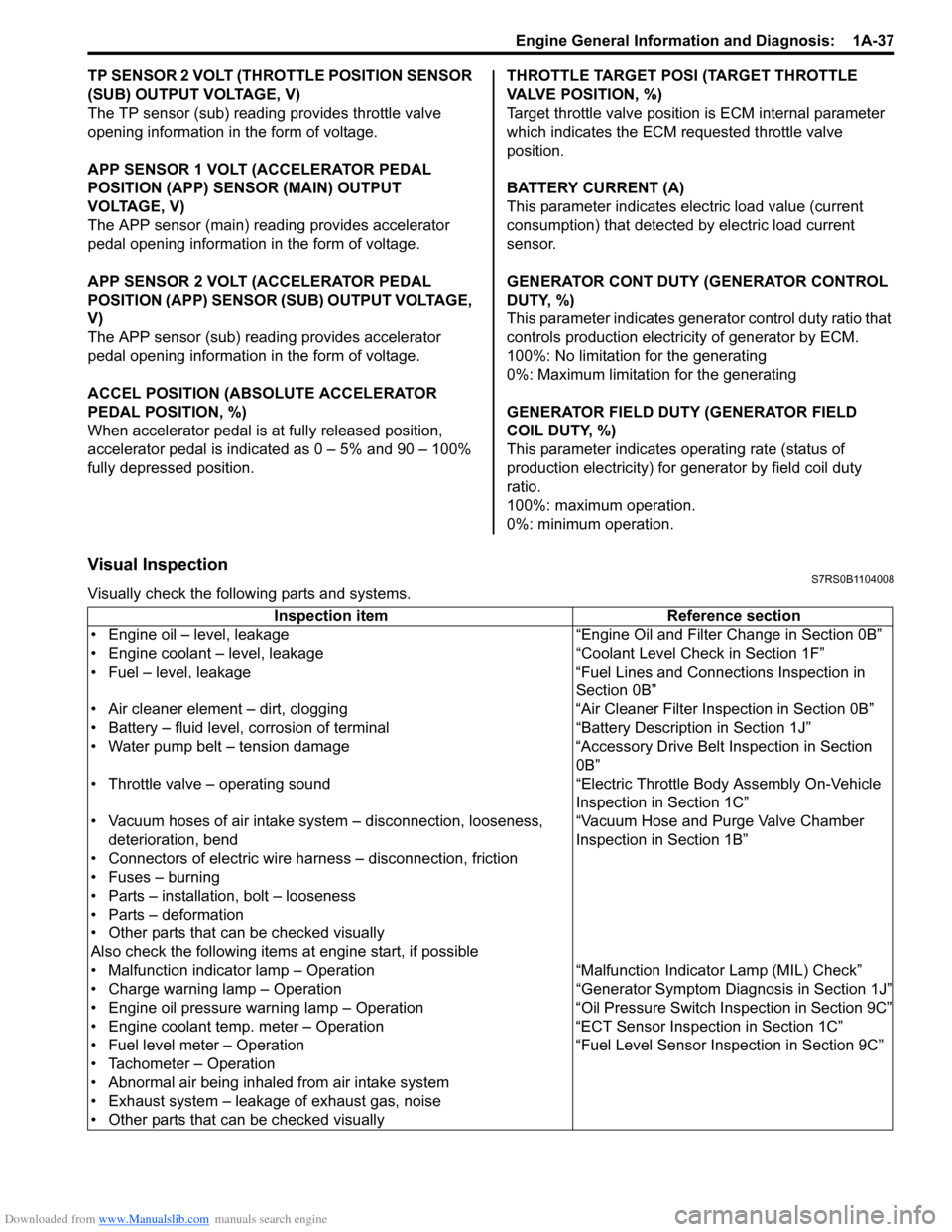
TP SENSOR 2 VOLT (THROTTLE POSITION SENSOR
(SUB) OUTPUT VOLTAGE, V)
The TP sensor (sub) reading provides throttle valve
opening information in the form of voltage.
APP SENSOR 1 VOLT (ACCELERATOR PEDAL
POSITION (APP) SENSOR (MAIN) OUTPUT
VOLTAGE, V)
The APP sensor (main) read ing provides accelerator
pedal opening information in the form of voltage.
APP SENSOR 2 VOLT (ACCELERATOR PEDAL
POSITION (APP) SENSOR (S UB) OUTPUT VOLTAGE,
V)
The APP sensor (sub) reading provides accelerator
pedal opening information in the form of voltage.
ACCEL POSITION (ABSOLUTE ACCELERATOR
PEDAL POSITION, %)
When accelerator pedal is at fully released position,
accelerator pedal is indicated as 0 – 5% and 90 – 100%
fully depressed position. THROTTLE TARGET POSI (TARGET THROTTLE
VALVE POSITION, %)
Target throttle valve position is ECM internal parameter
which indicates the ECM requested throttle valve
position.
BATTERY CURRENT (A)
This parameter indicates elec
tric load value (current
consumption) that detected by electric load current
sensor.
GENERATOR CONT DUTY (GENERATOR CONTROL
DUTY, %)
This parameter indicates generator control duty ratio that
controls production electricity of generator by ECM.
100%: No limitation for the generating
0%: Maximum limitation for the generating
GENERATOR FIELD DUTY (GENERATOR FIELD
COIL DUTY, %)
This parameter indicates ope rating rate (status of
production electricity) for gen erator by field coil duty
ratio.
100%: maximum operation.
0%: minimum operation.
Visual InspectionS7RS0B1104008
Visually check the following parts and systems.
Inspection item Reference section
• Engine oil – level, leakage “Engine Oil and Filter Change in Section 0B”
• Engine coolant – level, leakage “Co olant Level Check in Section 1F”
• Fuel – level, leakage “Fuel Lines and Connections Inspection in Section 0B”
• Air cleaner element – dirt, clogging “Air Cleaner Filter Inspection in Section 0B”
• Battery – fluid level, corrosion of terminal “Battery Description in Section 1J”
• Water pump belt – tension damage “Accessory Drive Belt Inspection in Section 0B”
• Throttle valve – operating sound “Electric Throttle Body Assembly On-Vehicle Inspection in Section 1C”
• Vacuum hoses of air intake system – disconnection, looseness,
deterioration, bend “Vacuum Hose and Purge Valve Chamber
Inspection in Section 1B”
• Connectors of electric wire harness – disconnection, friction
• Fuses – burning
• Parts – installation, bolt – looseness
• Parts – deformation
• Other parts that can be checked visually
Also check the following items at engine start, if possible
• Malfunction indicator lamp – Operation “Malfunction Indicator Lamp (MIL) Check”
• Charge warning lamp – Operation “Genera tor Symptom Diagnosis in Section 1J”
• Engine oil pressure warning lamp – Operation “O il Pressure Switch Inspection in Section 9C”
• Engine coolant temp. meter – Operation “ECT Sensor Inspection in Section 1C”
• Fuel level meter – Operation “Fuel Level Sensor Inspection in Section 9C”
• Tachometer – Operation
• Abnormal air being inhaled from air intake system
• Exhaust system – leakage of exhaust gas, noise
• Other parts that can be checked visually
Page 187 of 1496
Downloaded from www.Manualslib.com manuals search engine Engine General Information and Diagnosis: 1A-137
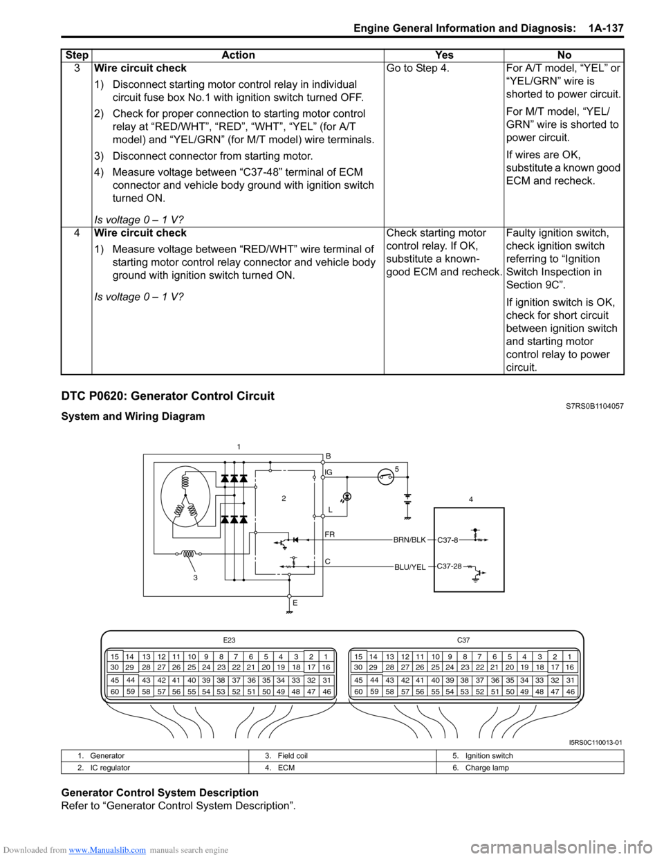
DTC P0620: Generator Control CircuitS7RS0B1104057
System and Wiring Diagram
Generator Control System Description
Refer to “Generator Control System Description”.3
Wire circuit check
1) Disconnect starting motor control relay in individual
circuit fuse box No.1 with ignition switch turned OFF.
2) Check for proper connection to starting motor control relay at “RED/WHT”, “RED”, “WHT”, “YEL” (for A/T
model) and “YEL/GRN” (for M/T model) wire terminals.
3) Disconnect connector from starting motor.
4) Measure voltage between “C37-48” terminal of ECM connector and vehicle body ground with ignition switch
turned ON.
Is voltage 0 – 1 V? Go to Step 4. For A/T model, “YEL” or
“YEL/GRN” wire is
shorted to power circuit.
For M/T model, “YEL/
GRN” wire is shorted to
power circuit.
If wires are OK,
substitute a known good
ECM and recheck.
4 Wire circuit check
1) Measure voltage between “RED/WHT” wire terminal of
starting motor control relay connector and vehicle body
ground with ignition switch turned ON.
Is voltage 0 – 1 V? Check starting motor
control relay. If OK,
substitute a known-
good ECM and recheck.
Faulty ignition switch,
check ignition switch
referring to “Ignition
Switch Inspection in
Section 9C”.
If ignition switch is OK,
check for short circuit
between ignition switch
and starting motor
control relay to power
circuit.
Step Action Yes No
IG
L
C
FR
E 4
2
BRN/BLKC37-8
BLU/YELC37-28
B
E23
C37
34
1819
567
1011
17
20
47 46
495051
2122
52 16
25 9
24
14
29
55
57 54 53
59
60 58 2
262728
15
30
56 4832 31
34353637
40
42 39 38
44
45 43 41 331
1213
238
34
1819
567
1011
17
20
47 46
495051
2122
52 16
25 9
24
14
29
55
57 54 53
59
60 58 2
262728
15
30
56 4832 31
34353637
40
42 39 38
44
45 43 41 331
1213
238 1
3 5
I5RS0C110013-01
1. Generator
3. Field coil 5. Ignition switch
2. IC regulator 4. ECM 6. Charge lamp
Page 284 of 1496
Downloaded from www.Manualslib.com manuals search engine 1C-12 Engine Electrical Devices:
MAF and IAT Sensor InspectionS7RS0B1306020
CAUTION!
Do not heat up MAF and IAT sensor more
than 100 °C (212 °F). Otherwise, MAF and IAT
sensor will be damaged.
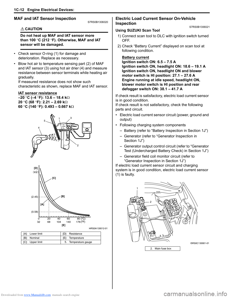
• Check sensor O-ring (1) for damage and deterioration. Replace as necessary.
• Blow hot air to temperature sensing part (2) of MAF and IAT sensor (3) using hot air drier (4) and measure
resistance between sensor terminals while heating air
gradually.
If measured resistance does not show such
characteristic as shown, replace MAF and IAT sensor.
IAT sensor resistance
–20 °C (–4 °F): 13.6 – 18.4 k Ω
20 °C (68 °F): 2.21 – 2.69 k Ω
60 °C (140 °F): 0.493 – 0.667 k Ω
Electric Load Current Sensor On-Vehicle
Inspection
S7RS0B1306021
Using SUZUKI Scan Tool
1) Connect scan tool to DLC with ignition switch turned OFF.
2) Check “Battery Current” displayed on scan tool at following condition.
Battery current
Ignition switch ON: 6.5 – 7.5 A
Ignition switch ON, headlight ON: 18.6 – 19.1 A
Ignition switch ON, headlight ON and blower
motor switch is HI position: 27.1 – 27.6 A
Engine running at idle speed, headlight ON,
blower motor switch is HI position and rear
defogger switch ON: 38.1 – 41.7 A
If check result is satisfactory, electric load current sensor
is in good condition.
If check result is not satisf actory, check the following
parts and circuit.
• Electric load current sensor circuit (power, ground and output)
• Following charging system components
– Battery (refer to “Battery Inspection in Section 1J”)
– Generator (refer to “Generator Inspection in Section 1J”)
– Generator output control ci rcuit (refer to “Generator
Test (Undercharged Battery Check) in Section 1J”)
– Generator field coil monitor circuit (refer to “Generator Inspection in Section 1J”)
If electric load current sensor circuit and charging
system is in good condition, electric load current sensor
(1) is faulty.
[A]: Lower limit [D]: Resistance
[B]: Nominal [E]: Temperature
[C]: Upper limit 5. Temperature gauge
200
6832104 140 17640 60 80
(2.45)
(0.58)
1
2
3
4 5
[A] [B]
[E]
[C]
[D]
I4RS0A130012-01
2. Main fuse box
2
1
I5RS0C130001-01
Page 285 of 1496
Downloaded from www.Manualslib.com manuals search engine Engine Electrical Devices: 1C-13
Without Using SUZUKI Scan Tool1) Measure sensor voltage between “C37-23” terminal of ECM connector and vehicle body ground referring
to “Inspection of ECM and Its Circuits in Section 1A”.
If check result is satisfactory, electric load current
sensor is in good condition.
If check result is not satisfactory, check the following
parts and circuit.
• Electric load current sensor circuit (power, ground and output)
• Following charging system components – Battery (refer to “Battery Inspection in Section
1J”)
– Generator (refer to “Generator Inspection in Section 1J”)
– Generator output control circuit (refer to “Generator Test (Undercharged Battery Check)
in Section 1J”)
– Generator field coil monitor circuit (refer to “Generator Inspection in Section 1J”) If electric load current sensor circuit and charging
system is in good condition,
electric load current sensor
(1) is faulty.
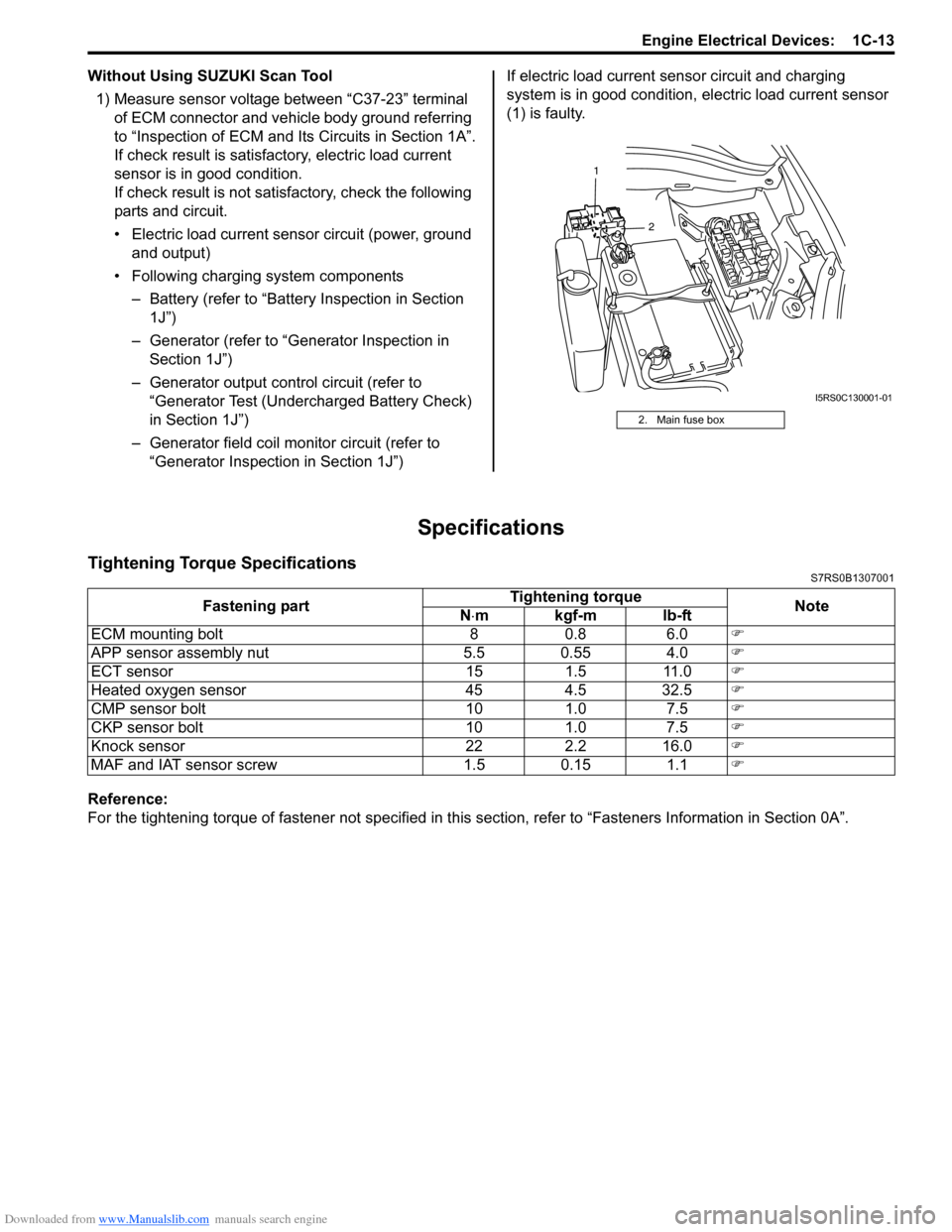
Specifications
Tightening Torque SpecificationsS7RS0B1307001
Reference:
For the tightening torque of fastener not specified in this section, refer to “Fasteners Information in Section 0A”.
2. Main fuse box
2
1
I5RS0C130001-01
Fastening part
Tightening torque
Note
N ⋅mkgf-mlb-ft
ECM mounting bolt 8 0.8 6.0 )
APP sensor assembly nut 5.5 0.55 4.0 )
ECT sensor 15 1.5 11.0 )
Heated oxygen sensor 45 4.5 32.5 )
CMP sensor bolt 10 1.0 7.5 )
CKP sensor bolt 10 1.0 7.5 )
Knock sensor 22 2.2 16.0 )
MAF and IAT sensor screw 1.5 0.15 1.1 )
Page 367 of 1496
Downloaded from www.Manualslib.com manuals search engine Engine Cooling System: 1F-4
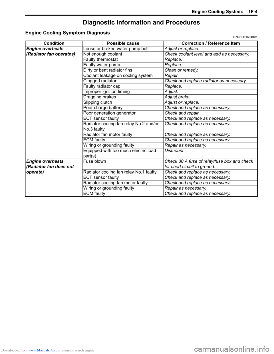
Diagnostic Information and Procedures
Engine Cooling Symptom DiagnosisS7RS0B1604001
ConditionPossible cause Correction / Reference Item
Engine overheats
(Radiator fan operates) Loose or broken water pump belt
Adjust or replace.
Not enough coolant Check coolant level and add as necessary.
Faulty thermostat Replace.
Faulty water pump Replace.
Dirty or bent radiator fins Clean or remedy.
Coolant leakage on cooling system Repair.
Clogged radiator Check and replace radiator as necessary.
Faulty radiator cap Replace.
Improper ignition timing Adjust.
Dragging brakes Adjust brake.
Slipping clutch Adjust or replace.
Poor charge battery Check and replace as necessary.
Poor generation generator Check and repair.
ECT sensor faulty Check and replace as necessary.
Radiator cooling fan relay No.2 and/or
No.3 faulty Check and replace as necessary.
Radiator fan motor faulty Check and replace as necessary.
ECM faulty Check and replace as necessary.
Wiring or grounding faulty Repair as necessary.
Equipped with too much electric load
part(s) Dismount.
Engine overheats
(Radiator fan does not
operate) Fuse blown
Check 30 A fuse of relay/fuse box and check
for short circuit to ground.
Radiator cooling fan relay No.1 faulty Check and replace as necessary.
ECT sensor faulty Check and replace as necessary.
Radiator cooling fan motor faulty Check and replace as necessary.
Wiring or grounding faulty Repair as necessary.
ECM faulty Check and replace as necessary.
Page 403 of 1496
Downloaded from www.Manualslib.com manuals search engine Starting System: 1I-2
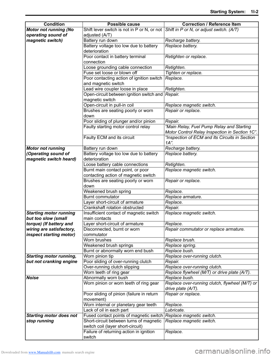
ConditionPossible cause Correction / Reference Item
Motor not running (No
operating sound of
magnetic switch) Shift lever switch is not in P or N, or not
adjusted (A/T)
Shift in P or N, or
adjust switch. (A/T)
Battery run down Recharge battery.
Battery voltage too low due to battery
deterioration Replace battery.
Poor contact in battery terminal
connection Retighten or replace.
Loose grounding cable connection Retighten.
Fuse set loose or blown off Tighten or replace.
Poor contacting action of ignition switch
and magnetic switch Replace.
Lead wire coupler loose in place Retighten.
Open-circuit between ignition switch and
magnetic switch Repair.
Open-circuit in pull-in coil Replace magnetic switch.
Brushes are seating poorly or worn
down Repair or replace.
Poor sliding of plunger and/or pinion Repair.
Faulty starting motor control relay “Main Relay, Fuel Pump Relay and Starting
Motor Control Relay Inspection in Section 1C”.
Faulty ECM and its circuit “Inspection of ECM and Its Circuits in Section
1A”.
Motor not running
(Operating sound of
magnetic switch heard) Battery run down
Recharge battery.
Battery voltage too low due to battery
deterioration Replace battery.
Loose battery cable connections Retighten.
Burnt main contact point, or poor
contacting action of magnetic switch Replace magnetic switch.
Brushes are seating poorly or worn
down Repair or replace.
Weakened brush spring Replace.
Burnt commutator Replace armature.
Layer short-circuit of armature Replace.
Crankshaft rotation obstructed Repair.
Starting motor running
but too slow (small
torque) (If battery and
wiring are satisfactory,
inspect starting motor) Insufficient contact
of magnetic switch
main contacts Replace magnetic switch.
Layer short-circuit of armature Replace.
Disconnected, burnt or worn
commutator Repair commutator or replace armature.
Worn brushes Replace brush.
Weakened brush springs Replace spring.
Burnt or abnormally worn end bush Replace bush.
Starting motor running,
but not cranking engine Worn pinion tip
Replace over-running clutch.
Poor sliding of over-running clutch Repair.
Over-running clutch slipping Replace over-running clutch.
Worn teeth of ring gear Replace flywheel (M/T) or drive plate (A/T).
Noise Abnormally worn bush Replace bush.
Worn pinion or worn teeth of ring gear Replace over-running clutch, flywheel (M/T) or
drive plate (A/T).
Poor sliding of pinion (failure in return
movement) Repair or replace.
Worn internal or planetary gear teeth Replace.
Lack of oil in each part Lubricate.
Starting motor does not
stop running Fused contact points of magnetic switch
Replace magnetic switch.
Short-circuit between turns of magnetic
switch coil (layer short-circuit) Replace magnetic switch.
Failure of returning action in ignition
switch Replace.
Page 414 of 1496
Downloaded from www.Manualslib.com manuals search engine 1J-4 Charging System:
Diagnostic Information and Procedures
Battery InspectionS7RS0B1A04001
Common Causes of Failure
A battery is not designed to last indefinitely; however, with proper care, it will provide many years of service. If the
battery performs satisfactorily during te st but fails to operate properly for no apparent reason, the following are some
factors that may point to the cause of trouble:
• Accessories left on overnight or for an extended period without the generator operating.
• Slow average driving speeds for short periods.
• Electrical load exceeding generator output partic ularly with addition of aftermarket equipment.
• Defects in charging system such as high resistance, s lipping drive belt, loose generator output terminal, faulty
generator or voltage regulator, Refer to “Generator Symptom Diagnosis”.
• Battery abuse, including failure to keep battery cable terminals clean and tight or loose battery hold down.
• Mechanical problems in electrical sys tem such as shorted or pinched wires.
Visual Inspection
Check for obvious damage, such as cracked or broken case or cover, that could permit loss of electrolyte. If obvious
damage is noted, replace battery. Determine cause of damage and correct as needed.
Generator Symptom DiagnosisS7RS0B1A04002
CAUTION!
• Do not mistake polarities of “IG” terminal and “L” terminal.
• Do not create short circuit between “IG” and “L” terminals. Always connect these terminals through a lamp.
• Do not connect any load between “L” and “E” terminals.
• When connecting charger or booster battery to vehicle battery, refer to “Jump Starting in Case of Emergency”.
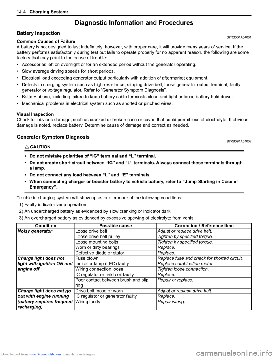
Trouble in charging system will show up as one or more of the following conditions:
1) Faulty indicator lamp operation.
2) An undercharged battery as evidenced by slow cranking or indicator dark.
3) An overcharged battery as evidenced by ex cessive spewing of electrolyte from vents.
Condition Possible cause Correction / Reference Item
Noisy generator Loose drive belt Adjust or replace drive belt.
Loose drive belt pulley Tighten by specified torque.
Loose mounting bolts Tighten by specified torque.
Worn or dirty bearings Replace.
Defective diode or stator Replace.
Charge light does not
light with ignition ON and
engine off Fuse blown
Replace fuse and check for shorted circuit.
Indicator lamp (LED) faulty Replace combination meter.
Wiring connection loose Tighten loose connection.
IC regulator or field coil faulty Replace.
Poor contact between brush and slip
ring Repair or replace.
Charge light does not go
out with engine running
(battery requires frequent
recharging) Drive belt loose or worn
Adjust or replace drive belt.
IC regulator or generator faulty Replace.
Wiring faulty Repair wiring.
Page 560 of 1496
Downloaded from www.Manualslib.com manuals search engine 4E-21 ABS:
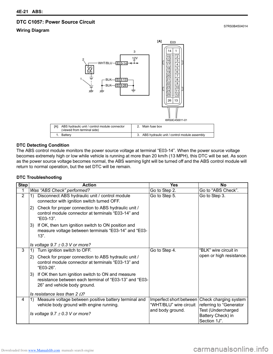
DTC C1057: Power Source CircuitS7RS0B4504014
Wiring Diagram
DTC Detecting Condition
The ABS control module monitors the power source voltage at terminal “E03-14”. When the power source voltage
becomes extremely high or low while vehicle is running at more than 20 km/h (13 MPH), this DTC will be set. As soon
as the power source volta ge becomes normal, the ABS warning light will be turned off and the ABS control module will
return to normal operation, bu t the set DTC will be remain.
DTC Troubleshooting
[A]: ABS hydraulic unit / control module connector (viewed from terminal side) 2. Main fuse box
1. Battery 3. ABS hydraulic unit / control module assembly
E03-14WHT/BLU
1 2
3
BLK
BLK
E03-13
E03-26
[A]
E03
15
16
17
18
19
20
21
22
23
24
25 2
3
4
5
6
7
8
9
10
11
12
1
13
14
26
12V
I6RS0C450011-01
Step
Action YesNo
1 Was “ABS Check” performed? Go to Step 2.Go to “ABS Check”.
2 1) Disconnect ABS hydraulic unit / control module connector with ignition switch turned OFF.
2) Check for proper connection to ABS hydraulic unit / control module connector at terminals “E03-14” and
“E03-13”.
3) If OK, then turn ignition switch to ON position and measure voltage between terminals “E03-14” and “E03-
13”.
Is voltage 9.7
± 0.3 V or more? Go to Step 5. Go to Step 3.
3 1) Turn ignition switch to OFF. 2) Check for proper connection to ABS hydraulic unit / control module connector at terminals “E03-13” and
“E03-26”.
3) If OK then turn ignition switch to ON and measure resistance between each terminal of “E03-13” and “E03-
26” and vehicle body ground.
Is resistance less than 2
Ω? Go to Step 4. “BLK” wire circuit in
open or high resistance.
4 1) Measure voltage between positive battery terminal and vehicle body ground with engine running.
Is voltage 9.7
± 0.3 V or more? Imperfect short between
“WHT/BLU” wire circuit
and body ground.
Check charging system
referring to “Generator
Test (Undercharged
Battery Check) in
Section 1J”.
Page 561 of 1496
Downloaded from www.Manualslib.com manuals search engine ABS: 4E-22
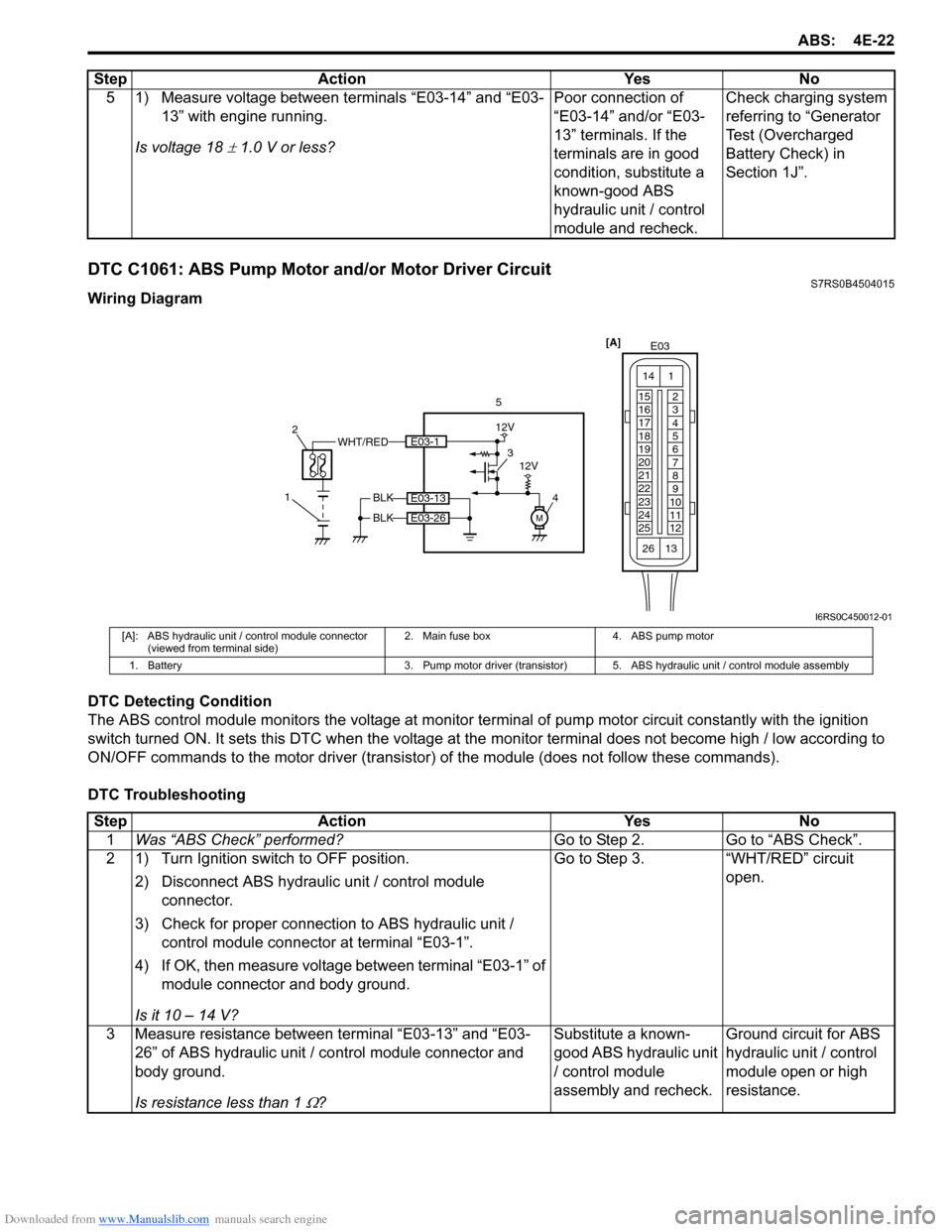
DTC C1061: ABS Pump Motor and/or Motor Driver CircuitS7RS0B4504015
Wiring Diagram
DTC Detecting Condition
The ABS control module monitors the voltage at monitor terminal of pump motor circuit constantly with the ignition
switch turned ON. It sets this DTC when the voltage at the monitor terminal does not become high / low according to
ON/OFF commands to the motor driver (transistor) of the module (does not follow these commands).
DTC Troubleshooting 5 1) Measure voltage between terminals “E03-14” and “E03-
13” with engine running.
Is voltage 18
± 1.0 V or less? Poor connection of
“E03-14” and/or “E03-
13” terminals. If the
terminals are in good
condition, substitute a
known-good ABS
hydraulic unit / control
module and recheck.Check charging system
referring to “Generator
Test (Overcharged
Battery Check) in
Section 1J”.
Step Action Yes No
WHT/RED
1 2
5
BLK
BLK
E03-13
E03-26
[A]
E03
15
16
17
18
19
20
21
22
23
24
25 2
3
4
5
6
7
8
9
10
11
12
1
13
14
26
M
3
4E03-1
12V
12V
I6RS0C450012-01
[A]: ABS hydraulic unit / control module connector (viewed from terminal side) 2. Main fuse box 4. ABS pump motor
1. Battery 3. Pump motor driver (transistor) 5. ABS hydraulic unit / control module assembly
StepAction YesNo
1 Was “ABS Check” performed? Go to Step 2.Go to “ABS Check”.
2 1) Turn Ignition switch to OFF position.
2) Disconnect ABS hydraulic unit / control module connector.
3) Check for proper connection to ABS hydraulic unit / control module connector at terminal “E03-1”.
4) If OK, then measure voltage between terminal “E03-1” of module connector and body ground.
Is it 10 – 14 V? Go to Step 3.
“WHT/RED” circuit
open.
3 Measure resistance between terminal “E03-13” and “E03- 26” of ABS hydraulic unit / co ntrol module connector and
body ground.
Is resistance less than 1
Ω? Substitute a known-
good ABS hydraulic unit
/ control module
assembly and recheck.
Ground circuit for ABS
hydraulic unit / control
module open or high
resistance.
Page 562 of 1496
Downloaded from www.Manualslib.com manuals search engine 4E-23 ABS:
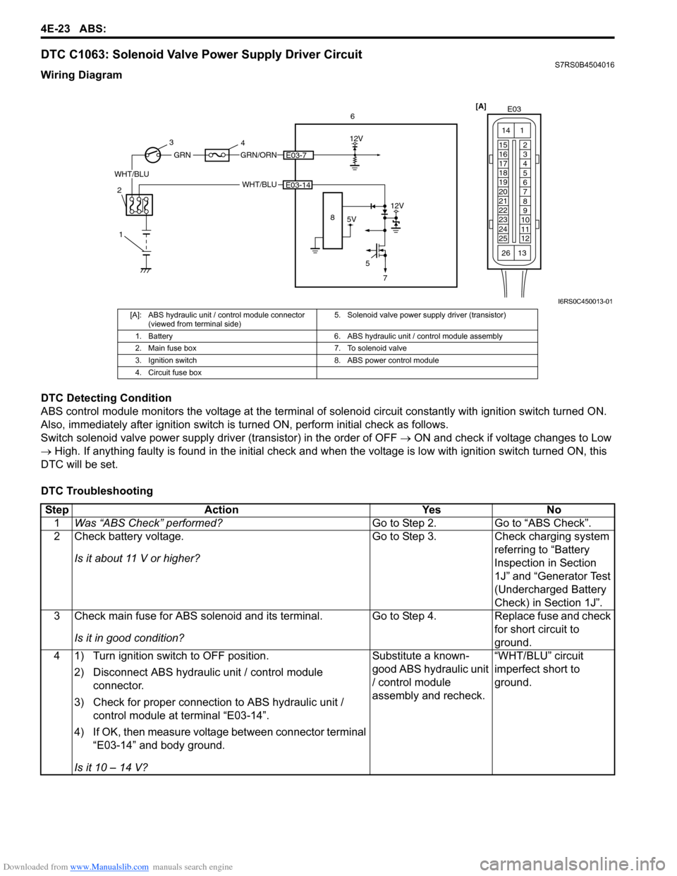
DTC C1063: Solenoid Valve Power Supply Driver CircuitS7RS0B4504016
Wiring Diagram
DTC Detecting Condition
ABS control module monitors the voltage at the terminal of solenoid circuit constantly with ignition switch turned ON.
Also, immediately after ignition switch is turned ON, perform initial check as follows.
Switch solenoid valve power supply driv er (transistor) in the order of OFF → ON and check if voltage changes to Low
→ High. If anything faulty is found in the initial check and when the voltage is low with ignition switch turned ON, this
DTC will be set.
DTC Troubleshooting
[A] E03
15
16
17
18
19
20
21
22
23
24
25 2
3
4
5
6
7
8
9
10
11
12
1
13
14
266
WHT/BLU
12V
5E03-14
5V
12V
8
GRN/ORNE03-7
WHT/BLU
GRN
1
2 3
4
7
I6RS0C450013-01
[A]: ABS hydraulic unit / control module connector
(viewed from terminal side) 5. Solenoid valve power supp
ly driver (transistor)
1. Battery 6. ABS hydraulic unit / control module assembly
2. Main fuse box 7. To solenoid valve
3. Ignition switch 8. ABS power control module
4. Circuit fuse box
Step Action YesNo
1 Was “ABS Check” performed? Go to Step 2.Go to “ABS Check”.
2 Check battery voltage.
Is it about 11 V or higher? Go to Step 3.
Check charging system
referring to “Battery
Inspection in Section
1J” and “Generator Test
(Undercharged Battery
Check) in Section 1J”.
3 Check main fuse for ABS solenoid and its terminal.
Is it in good condition? Go to Step 4.
Replace fuse and check
for short circuit to
ground.
4 1) Turn ignition switch to OFF position.
2) Disconnect ABS hydraulic unit / control module connector.
3) Check for proper connection to ABS hydraulic unit / control module at terminal “E03-14”.
4) If OK, then measure voltage between connector terminal “E03-14” and body ground.
Is it 10 – 14 V? Substitute a known-
good ABS hydraulic unit
/ control module
assembly and recheck.
“WHT/BLU” circuit
imperfect short to
ground.