ECO mode SUZUKI SWIFT 2007 2.G Service Workshop Manual
[x] Cancel search | Manufacturer: SUZUKI, Model Year: 2007, Model line: SWIFT, Model: SUZUKI SWIFT 2007 2.GPages: 1496, PDF Size: 34.44 MB
Page 3 of 1496
Downloaded from www.Manualslib.com manuals search engine FOREWORD
This manual (Volumes 1 and 2) contains procedures for diagnosis, maintenance, adjustments, minor service
operations, replacement of components (Service) and for disassembly and reassembly of major components
(Unit Repair-Overhaul).
Applicable Model:
SWIFT (RS416) produced at KOSAI plant in Japan wi th the following vehicle identification numbers
(VINs).
JSAEZC31S############
The contents are classified into sectio ns each of which is given a section number as indicated in the Table of
Contents on following page. And on the first page of ea ch individual section is an index of that section.
This manual should be kept in a handy place for ready reference of the service work.
Strict observance of the so specif ied items will enable one to obtain the full performance of the vehicle.
When replacing parts or servicing by disassembling, it is recommended to use SUZUKI genuine parts, tools and
service materials as specif ied in each description.
All information, illustrations and specif ications contained in this literature are based on the late st product infor-
mation available at the time of publication approval. And used as the main subject of description is the vehicle of
standard specificatio ns among others.
Therefore, note that illustrations may differ from the vehicle being actually serviced.
The right is reserved to make changes at any time without notice.
JSAEZC31S########
Page 43 of 1496
Downloaded from www.Manualslib.com manuals search engine Maintenance and Lubrication: 0B-13
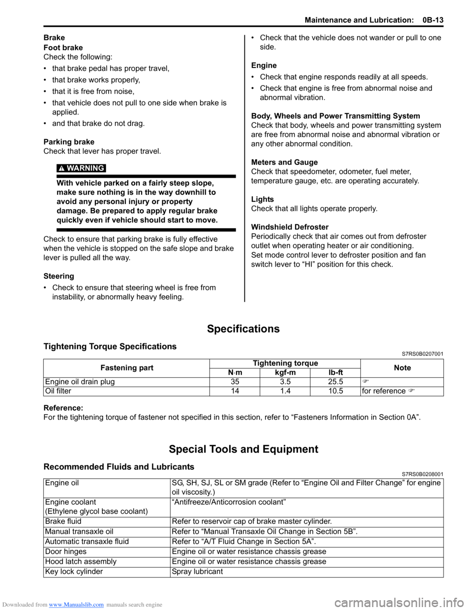
Brake
Foot brake
Check the following:
• that brake pedal has proper travel,
• that brake works properly,
• that it is free from noise,
• that vehicle does not pull to one side when brake is applied.
• and that brake do not drag.
Parking brake
Check that lever has proper travel.
WARNING!
With vehicle parked on a fairly steep slope,
make sure nothing is in the way downhill to
avoid any personal injury or property
damage. Be prepared to apply regular brake
quickly even if vehicle should start to move.
Check to ensure that parking brake is fully effective
when the vehicle is stopped on the safe slope and brake
lever is pulled all the way.
Steering
• Check to ensure that steering wheel is free from instability, or abnormally heavy feeling. • Check that the vehicle does not wander or pull to one
side.
Engine
• Check that engine responds readily at all speeds.
• Check that engine is free from abnormal noise and abnormal vibration.
Body, Wheels and Power Transmitting System
Check that body, wheels and power transmitting system
are free from abnormal noise and abnormal vibration or
any other abnormal condition.
Meters and Gauge
Check that speedometer, odometer, fuel meter,
temperature gauge, etc. are operating accurately.
Lights
Check that all lights operate properly.
Windshield Defroster
Periodically check that ai r comes out from defroster
outlet when operating heater or air conditioning.
Set mode control lever to defroster position and fan
switch lever to “HI” position for this check.
Specifications
Tightening Torque SpecificationsS7RS0B0207001
Reference:
For the tightening torque of fastener not specified in this section, refer to “Fasteners Information in Section 0A”.
Special Tools and Equipment
Recommended Fluids and LubricantsS7RS0B0208001
Fastening part Tightening torque
Note
N ⋅mkgf-mlb-ft
Engine oil drain plug 35 3.5 25.5 �)
Oil filter 14 1.4 10.5 for reference �)
Engine oilSG, SH, SJ, SL or SM grade (Refer to “Engine Oil and Filter Change” for engine
oil viscosity.)
Engine coolant
(Ethylene glycol base coolant) “Antifreeze/Antico
rrosion coolant”
Brake fluid Refer to reservoir cap of brake master cylinder.
Manual transaxle oil Refer to “Manual Transaxle Oil Change in Section 5B”.
Automatic transaxle fluid Refer to “A/T Fluid Change in Section 5A”.
Door hinges Engine oil or water resistance chassis grease
Hood latch assembly Engine oil or water resistance chassis grease
Key lock cylinder Spray lubricant
Page 60 of 1496
Downloaded from www.Manualslib.com manuals search engine 1A-10 Engine General Information and Diagnosis:
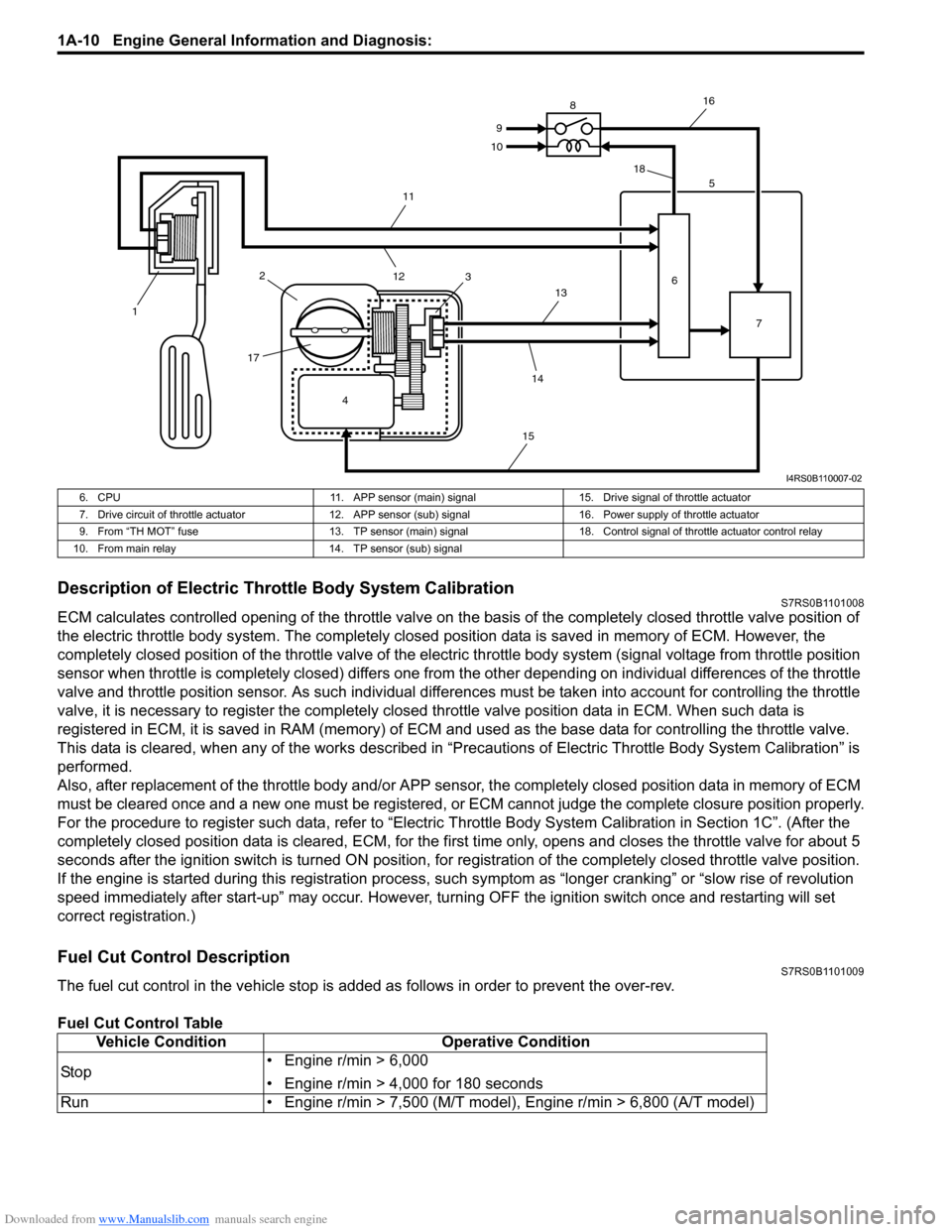
Description of Electric Throttle Body System CalibrationS7RS0B1101008
ECM calculates controlled opening of the throttle valve on the basis of the completely closed throttle valve position of
the electric throttle body system. The completely closed position data is saved in memory of ECM. However, the
completely closed position of the throttle valve of the electric throttle body system (signal voltage from throttle position
sensor when throttle is completely closed) differs one from the other depending on individual differences of the throttle
valve and throttle position sensor. As such individual diff erences must be taken into account for controlling the throttle
valve, it is necessary to register the completely closed throttle valve position data in ECM. When such data is
registered in ECM, it is sa ved in RAM (memory) of ECM and used as the base data for controlling the throttle valve.
This data is cleared, when any of the works described in “Preca utions of Electric Throttle Body System Calibration” is
performed.
Also, after replacement of the throttle body and/or APP sensor , the completely closed position data in memory of ECM
must be cleared once and a new one must be registered, or ECM cannot judge the complete closure position properly.
For the procedure to register such data, refer to “Electric Throttle Body System Calibration in Section 1C”. (After the
completely closed position data is cleared , ECM, for the first time only, opens and closes the throttle valve for about 5
seconds after the ignition switch is turned ON position, for re gistration of the completely closed throttle valve position.
If the engine is started during this registration process, such symptom as “longe r cranking” or “slow rise of revolution
speed immediately after start-up” may occur. However, turning OFF the ignition switch once and restarting will set
correct registration.)
Fuel Cut Control DescriptionS7RS0B1101009
The fuel cut control in the vehicle stop is add ed as follows in order to prevent the over-rev.
Fuel Cut Control Table
4
1
2
17 3 5
6 7
8
9
10
11
12 13
14
15 16
18
I4RS0B110007-02
6. CPU 11. APP sensor (main) signal15. Drive signal of throttle actuator
7. Drive circuit of throttle actuator 12. APP sensor (sub) signal 16. Power supply of throttle actuator
9. From “TH MOT” fuse 13. TP sensor (main) signal 18. Control signal of throttle actuator control relay
10. From main relay 14. TP sensor (sub) signal
Vehicle ConditionOperative Condition
Sto p • Engine r/min > 6,000
• Engine r/min > 4,000 for 180 seconds
Run • Engine r/min > 7,500 (M/T model), Engine r/min > 6,800 (A/T model)
Page 77 of 1496
Downloaded from www.Manualslib.com manuals search engine Engine General Information and Diagnosis: 1A-27
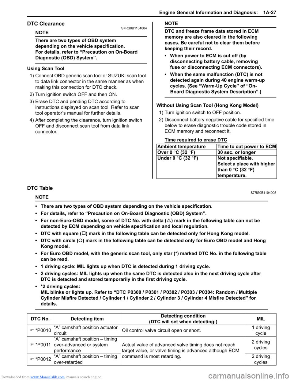
DTC ClearanceS7RS0B1104004
NOTE
There are two types of OBD system
depending on the vehicle specification.
For details, refer to “Precaution on On-Board
Diagnostic (OBD) System”.
Using Scan Tool1) Connect OBD generic scan to ol or SUZUKI scan tool
to data link connector in the same manner as when
making this connection for DTC check.
2) Turn ignition switch OFF and then ON.
3) Erase DTC and pending DTC according to instructions displayed on scan tool. Refer to scan
tool operator’s manual for further details.
4) After completing the clear ance, turn ignition switch
OFF and disconnect scan tool from data link
connector.
NOTE
DTC and freeze frame data stored in ECM
memory are also cleared in the following
cases. Be careful not to clear them before
keeping their record.
• When power to ECM is cut off (by disconnecting battery cable, removing
fuse or disconnecting ECM connectors).
• When the same malfunction (DTC) is not detected again during 40 engine warm-up
cycles. (See “Warm-Up Cycle” of “On-
Board Diagnostic System Description”.)
Without Using Scan Tool (Hong Kong Model)
1) Turn ignition switch to OFF position.
2) Disconnect battery negative cable for specified time below to erase diagnostic trouble code stored in
ECM memory and reconnect it.
Time required to erase DTC
DTC TableS7RS0B1104005
NOTE
• There are two types of OBD system depending on the vehicle specification.
• For details, refer to “Precaution on On-Board Diagnostic (OBD) System”.
• For non-Euro-OBD model, some of DTC No. with delta ( �U) mark in the following table can not be
detected by ECM depending on vehicl e specification and local regulation.
• DTC with square ( �†) mark in the following table can be detected only for Hong Kong model.
• DTC with circle ( �{) mark in the following table can be detected only for Euro OBD model and Hong
Kong model.
• For Euro OBD model, with the generic scan tool, onl y star (*) marked DTC No. in the following table
can be read.
• 1 driving cycle: MIL lights up when DTC is detected during 1 driving cycle.
• 2 driving cycles: MIL lights up when the same DTC is detected also in the next driving cycle after DTC is detected and stored temporarily in the first driving cycle.
• *2 driving cycles: MIL blinks or lights up. Refer to “DTC P0300 / P0301 / P0302 / P0303 / P0304: Random / Multiple
Cylinder Misfire Detected / Cylinder 1 / Cylinder 2 / Cylinder 3 / Cylinder 4 Misfire Detected” for
details.
Ambient temperature Time to cut power to ECM
Over 0 °C (32 ° F) 30 sec. or longer
Under 0 °C (32 °F) Not specifiable.
Select a place with higher
than 0 °C (32 °F)
temperature.
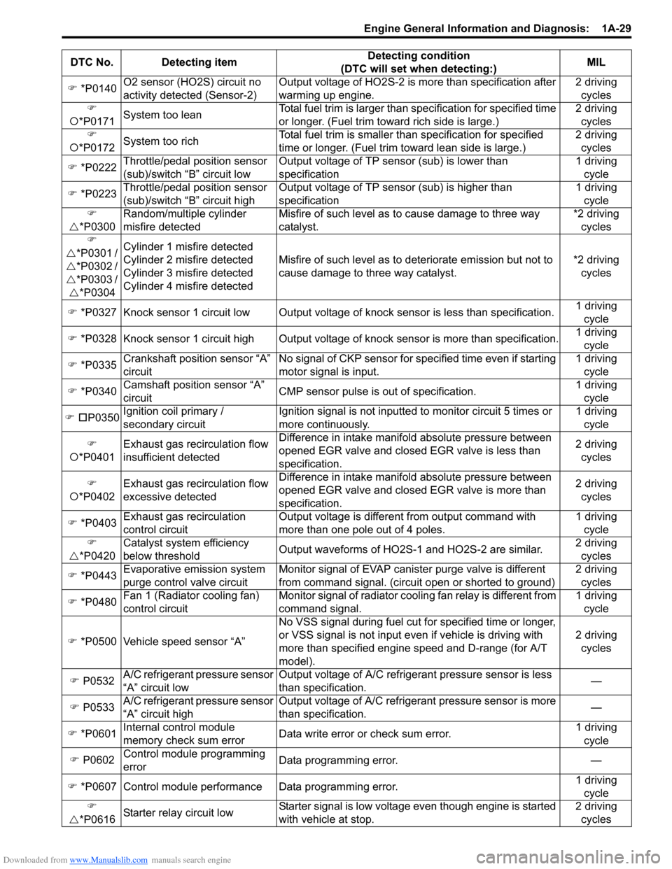
DTC No. Detecting item Detecting condition
(DTC will set when detecting:) MIL
�) *P0010 “A” camshaft position actuator
circuit Oil control valve circuit open or short. 1 driving
cycle
�) *P0011 “A” camshaft position – timing
over-advanced or system
performance Actual value of advanced va
lve timing does not reach
target value, or valve timi ng is advanced although ECM
command is most retarding. 2 driving
cycles
�) *P0012 “A” camshaft position – timing
over-retarded 2 driving
cycles
Page 79 of 1496
Downloaded from www.Manualslib.com manuals search engine Engine General Information and Diagnosis: 1A-29
�) *P0140 O2 sensor (HO2S) circuit no
activity detected (Sensor-2) Output voltage of HO2S-2 is more than specification after
warming up engine. 2 driving
cycles
�)
�{ *P0171 System too lean Total fuel trim is larger than
specification for specified time
or longer. (Fuel trim towa rd rich side is large.) 2 driving
cycles
�)
�{ *P0172 System too rich Total fuel trim is smaller th
an specification for specified
time or longer. (Fue l trim toward lean side is large.) 2 driving
cycles
�) *P0222 Throttle/pedal position sensor
(sub)/switch “B” circuit low Output voltage of TP sensor (sub) is lower than
specification 1 driving
cycle
�) *P0223 Throttle/pedal position sensor
(sub)/switch “B” circuit high Output voltage of TP sensor (sub) is higher than
specification 1 driving
cycle
�)
�U *P0300 Random/multiple cylinder
misfire detected Misfire of such level as to cause damage to three way
catalyst. *2 driving
cycles
�)
�U *P0301 /
�U *P0302 /
�U *P0303 /
�U *P0304 Cylinder 1 misfire detected
Cylinder 2 misfire detected
Cylinder 3 misfire detected
Cylinder 4 misfire detected
Misfire of such level as to deteriorate emission but not to
cause damage to three way catalyst.
*2 driving
cycles
�) *P0327 Knock sensor 1 circuit low Output voltage of knock sensor is less than specification.1 driving
cycle
�) *P0328 Knock sensor 1 circuit high Output volta ge of knock sensor is more than specification.1 driving
cycle
�) *P0335 Crankshaft position sensor “A”
circuit No signal of CKP sensor for sp
ecified time even if starting
motor signal is input. 1 driving
cycle
�) *P0340 Camshaft position sensor “A”
circuit CMP sensor pulse is out of specification. 1 driving
cycle
�) �† P0350 Ignition c
oil primary /
secondary circuit Ignition signal is not inputted to monitor circuit 5 times or
more continuously. 1 driving
cycle
�)
�{ *P0401 Exhaust gas recirculation flow
insufficient detected Difference in intake manifold absolute pressure between
opened EGR valve and closed EGR valve is less than
specification. 2 driving
cycles
�)
�{ *P0402 Exhaust gas recirculation flow
excessive detected Difference in intake manifold absolute pressure between
opened EGR valve and closed EGR valve is more than
specification. 2 driving
cycles
�) *P0403 Exhaust gas recirculation
control circuit Output voltage is different from output command with
more than one pole out of 4 poles. 1 driving
cycle
�)
�U *P0420 Catalyst system efficiency
below threshold
Output waveforms of HO2S-1 and HO2S-2 are similar. 2 driving
cycles
�) *P0443 Evaporative emission system
purge control valve circuit Monitor signal of EVAP canister purge valve is different
from command signal. (circuit open or shorted to ground) 2 driving
cycles
�) *P0480 Fan 1 (Radiator cooling fan)
control circuit Monitor signal of radiator cooling fan relay is different from
command signal. 1 driving
cycle
�) *P0500 Vehicle speed sensor “A” No VSS signal during fuel cut fo
r specified time or longer,
or VSS signal is not input even if vehicle is driving with
more than specified engine speed and D-range (for A/T
model). 2 driving
cycles
�) P0532 A/C refrigerant pressure sensor
“A” circuit low Output voltage of A/C refrigerant pressure sensor is less
than specification.
—
�) P0533 A/C refrigerant pressure sensor
“A” circuit high Output voltage of A/C refrigerant pressure sensor is more
than specification.
—
�) *P0601 Internal control module
memory check sum error Data write error or check sum error. 1 driving
cycle
�) P0602 Control module programming
error Data programming error.
—
�) *P0607 Control module performance Data programming error. 1 driving
cycle
�)
�U *P061
6Starter relay circuit low Starter signal is low voltage even though engine is started
with vehicle at stop. 2 driving
cycles
DTC No. Detecting item
Detecting condition
(DTC will set when detecting:) MIL
Page 89 of 1496
Downloaded from www.Manualslib.com manuals search engine Engine General Information and Diagnosis: 1A-39
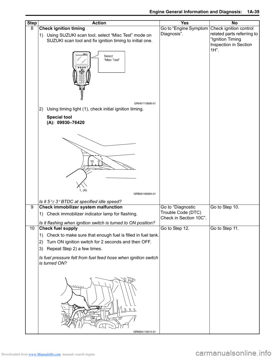
8Check ignition timing
1) Using SUZUKI scan tool, select “Misc Test” mode on
SUZUKI scan tool and fix ignition timing to initial one.
2) Using timing light (1), check initial ignition timing. Special tool
(A): 09930–76420
Is it 5
°± 3° BTDC at specif ied idle speed? Go to “Engine Symptom
Diagnosis”.
Check ignition control
related parts referring to
“Ignition Timing
Inspection in Section
1H”.
9 Check immobilizer system malfunction
1) Check immobilizer indica tor lamp for flashing.
Is it flashing when ignition switch is turned to ON position? Go to “Diagnostic
Trouble Code (DTC)
Check in Section 10C”.
Go to Step 10.
10 Check fuel supply
1) Check to make sure that enough fuel is filled in fuel tank.
2) Turn ON ignition switch for 2 seconds and then OFF.
3) Repeat Step 2) a few times.
Is fuel pressure felt from fuel feed hose when ignition switch
is turned ON? Go to Step 12. Go to Step 11.
Step Action Yes No
I2RH01110006-01
1, (A)
10
0I3RB0A180004-01
I3RM0A110014-01
Page 179 of 1496
Downloaded from www.Manualslib.com manuals search engine Engine General Information and Diagnosis: 1A-129
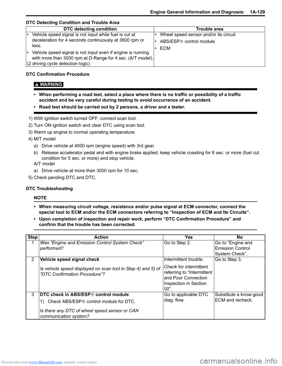
DTC Detecting Condition and Trouble Area
DTC Confirmation Procedure
WARNING!
• When performing a road test, select a place where there is no traffic or possibility of a traffic accident and be very careful during testing to avoid occurrence of an accident.
• Road test should be carried out by 2 persons, a driver and a tester.
1) With ignition switch turned OFF, connect scan tool.
2) Turn ON ignition switch and clear DTC using scan tool.
3) Warm up engine to normal operating temperature.
4) M/T model
a) Drive vehicle at 4000 rpm (e ngine speed) with 3rd gear.
b) Release accelerator pedal and with engine brake applied, keep vehicle coasting for 6 sec. or more (fuel cut condition for 5 sec. or more) and stop vehicle.
A/T model
a) Drive vehicle at more than 3000 rpm for 10 sec.
5) Check pending DTC and DTC.
DTC Troubleshooting
NOTE
• When measuring circuit voltage, resistance and/ or pulse signal at ECM connector, connect the
special tool to ECM and/or the ECM connectors re ferring to “Inspection of ECM and Its Circuits”.
• Upon completion of inspection and repair work, perform “DTC Confirmation Procedure” and confirm that the trouble has been corrected.
DTC detecting condition Trouble area
• Vehicle speed signal is not input while fuel is cut at deceleration for 4 seconds continuously at 3600 rpm or
less.
• Vehicle speed signal is not input even if engine is running with more than 3000 rpm at D-Range for 4 sec. (A/T model).
(2 driving cycle detection logic) • Wheel speed sensor and/or its circuit
• ABS/ESP®
control module
•ECM
Step Action YesNo
1 Was “Engine and Emission Control System Check”
performed? Go to Step 2.
Go to “Engine and
Emission Control
System Check”.
2 Vehicle speed signal check
Is vehicle speed displayed on scan tool in Step 4) and 5) of
“DTC Confirmation Procedure”? Intermittent trouble.
Check for intermittent
referring to “Intermittent
and Poor Connection
Inspection in Section
00”.Go to Step 3.
3 DTC check in ABS/ESP ® control module
1) Check ABS/ESP ® control module for DTC.
Is there any DTC of wheel speed sensor or CAN
communication system? Go to applicable DTC
diag. flow.
Substitute a know-good
ECM and recheck.
Page 256 of 1496
Downloaded from www.Manualslib.com manuals search engine 1A-206 Engine General Information and Diagnosis:
Troubleshooting
NOTE
• When measuring circuit voltage, resistance and/or pulse signal at ECM connector, connect the
special tool to ECM and/or the ECM connectors re ferring to “Inspection of ECM and Its Circuits”.
• When A/C evaporator outlet air temp. is below 2.5 °C (36.5 °F), A/C remains OFF (“E23-47” terminal
voltage becomes 10 – 14 V). This condition is not abnormal.
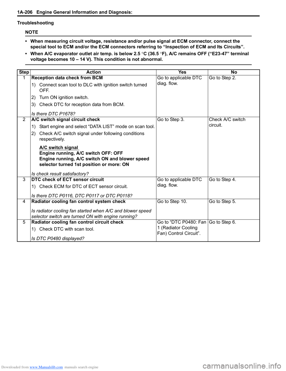
Step Action YesNo
1 Reception data check from BCM
1) Connect scan tool to DLC with ignition switch turned
OFF.
2) Turn ON ignition switch.
3) Check DTC for reception data from BCM.
Is there DTC P1678? Go to applicable DTC
diag. flow.
Go to Step 2.
2 A/C switch signal circuit check
1) Start engine and select “DATA LIST” mode on scan tool.
2) Check A/C switch signal under following conditions
respectively.
A/C switch signal
Engine running, A/C switch OFF: OFF
Engine running, A/C switch ON and blower speed
selector turned 1st position or more: ON
Is check result satisfactory? Go to Step 3. Check A/C switch
circuit.
3 DTC check of ECT sensor circuit
1) Check ECM for DTC of ECT sensor circuit.
Is there DTC P0116, DTC P0117 or DTC P0118? Go to applicable DTC
diag. flow.
Go to Step 4.
4 Radiator cooling fan control system check
Is radiator cooling fan started when A/C and blower speed
selector switch are turned ON with engine running? Go to Step 10. Go to Step 5.
5 Radiator cooling fan control circuit check
1) Check DTC with scan tool.
Is DTC P0480 displayed? Go to “DTC P0480: Fan
1 (Radiator Cooling
Fan) Control Circuit”.
Go to Step 6.
Page 277 of 1496
Downloaded from www.Manualslib.com manuals search engine Engine Electrical Devices: 1C-5
Electric Throttle Body System CalibrationS7RS0B1306004
NOTE
If working the service described under the
“Precautions of Electric Throttle Body
System Calibration in Section 1A” perform
following steps for electric throttle body
system calibration.
1) If electric throttle body assembly and/or APP sensor
assembly are replaced, perform following steps.
a) Disconnect negative cable at battery for 20 seconds or more for the purpose of clearing
calibration data of closed throttle position from
memory in ECM.
b) Connect negative cable to battery.
2) Keep ignition switch at ON position for 5 seconds or more without running engine.
APP Sensor Assembly On-Vehicle InspectionS7RS0B1306005
1) Check that APP sensor a ssembly has been mounted
to vehicle body properly (no pinched floor carpet,
etc.).
If mounting is not pro perly, reinstall APP sensor
assembly properly refe rring to “APP Sensor
Assembly Removal and Installation”.
2) Connect scan tool to DLC with ignition switch turned OFF.
3) Turn ON ignition switch and select “Data List” mode on scan tool.
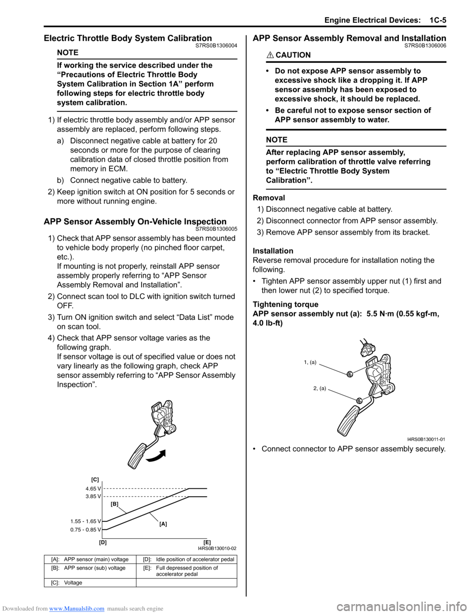
4) Check that APP sensor voltage varies as the following graph.
If sensor voltage is out of specified value or does not
vary linearly as the fo llowing graph, check APP
sensor assembly referring to “APP Sensor Assembly
Inspection”.
APP Sensor Assembly Removal and InstallationS7RS0B1306006
CAUTION!
• Do not expose APP sensor assembly to
excessive shock like a dropping it. If APP
sensor assembly has been exposed to
excessive shock, it should be replaced.
• Be careful not to expose sensor section of APP sensor assembly to water.
NOTE
After replacing APP sensor assembly,
perform calibration of th rottle valve referring
to “Electric Throttle Body System
Calibration”.
Removal
1) Disconnect negative cable at battery.
2) Disconnect connector from APP sensor assembly.
3) Remove APP sensor asse mbly from its bracket.
Installation
Reverse removal procedure for installation noting the
following.
• Tighten APP sensor assembly upper nut (1) first and then lower nut (2) to specified torque.
Tightening torque
APP sensor assembly nut (a): 5.5 N·m (0.55 kgf-m,
4.0 lb-ft)
• Connect connector to APP sensor assembly securely.
[A]: APP sensor (main) voltage [D]: Idle position of accelerator pedal
[B]: APP sensor (sub) voltage [E]: Full depressed position of
accelerator pedal
[C]: Voltage
[C]
[B]
[D] [E] [A]
4.65 V
3.85 V
1.55 - 1.65 V
0.75 - 0.85 V
I4RS0B130010-02
1, (a)
2, (a)
I4RS0B130011-01
Page 364 of 1496
Downloaded from www.Manualslib.com manuals search engine 1F-1 Engine Cooling System:
Engine
Engine Cooling System
General Description
Cooling System DescriptionS7RS0B1601001
The cooling system consists of the radiator cap, radiator, coolant reservoir, hoses, water pump, cooling fan and
thermostat. The radiator is of tube-and-fin type.
Coolant DescriptionS7RS0B1601002
WARNING!
• Do not remove radiator cap to check engine coolant level; check coolant visually at the see-through coolant reservoir. Coolant should be added only to reservoir as necessary.
• As long as there is pressure in the cooling system, the temperature can be considerably higher than the boiling temperature of the solution in the radiator without causing the solution to boil. Removal
of the radiator cap while engine is hot and pressure is high will cause the solution to boil
instantaneously and possibly with explosive force, spewing the solution over engine, fenders and
person removing cap. If the solution contains flammable anti-freeze such as alcohol (not
recommended for use at any time), there is also the possibility of causing a serious fire.
• Check to make sure that engine coolant temperature is cold before removing any part of cooling system.
• Also be sure to disconnect negative cable from battery terminal before removing any part.
The coolant recovery system is standard. The coolant in the radiator expands with heat, and the coolant is overflowed
to the reservoir.
When the system cools down, the coolant is drawn back into the radiator.
The cooling system has be en filled with a quality coolant that is a 50/50 mixture of water and ethylene glycol
antifreeze.
This 50/50 mixture coolant solution provides freezing protection to –36 °C (–33 °F).
• Maintain cooling system freeze protection at –36 °C (–33 °F) to ensure protection against corrosion and loss of
coolant from boiling. This should be done even if freezing temperatures are not expected.
• Add ethylene glycol base coolant when coolant has to be added because of coolant loss or to provide added protection against freezing at temperature lower than –36 °C (–33 °F).
NOTE
• Alcohol or methanol base coolant or plain water alone should not be used in cooling system at any
time as damage to cooling system could occur.
• Coolant must be mixed with deminerated water or distilled water.
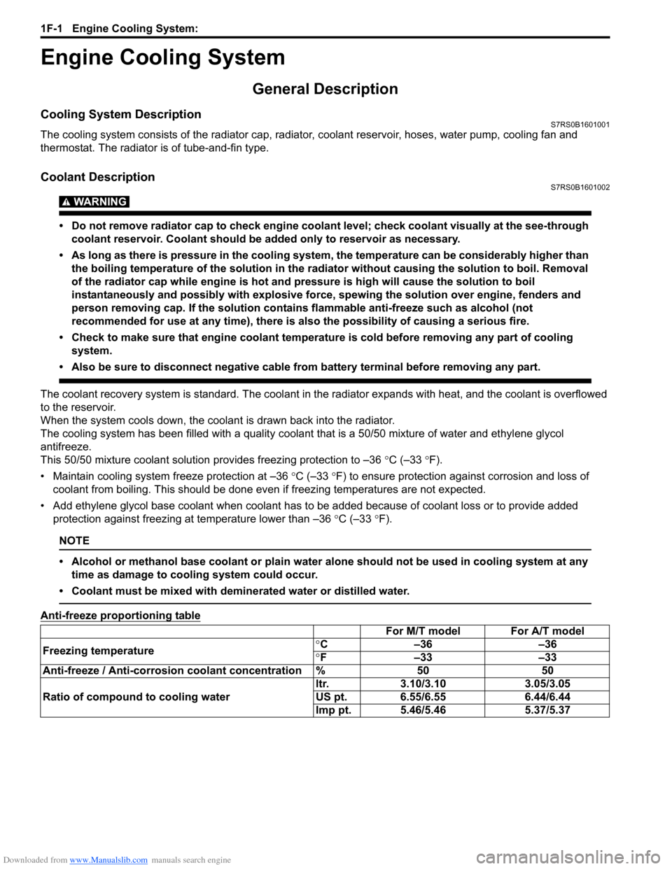
Anti-freeze proportioning table
For M/T model For A/T model
Freezing temperature °
C –36 –36
° F –33 –33
Anti-freeze / Anti-corrosion coolant concentration % 50 50
Ratio of compound to cooling water ltr. 3.10/3.10 3.05/3.05
US pt. 6.55/6.55 6.44/6.44
Imp pt. 5.46/5.46 5.37/5.37