ECU connector wiring SUZUKI SWIFT 2007 2.G Service Workshop Manual
[x] Cancel search | Manufacturer: SUZUKI, Model Year: 2007, Model line: SWIFT, Model: SUZUKI SWIFT 2007 2.GPages: 1496, PDF Size: 34.44 MB
Page 13 of 1496
Downloaded from www.Manualslib.com manuals search engine Precautions: 00-8
Precautions for Electrical Circuit ServiceS7RS0B0000008
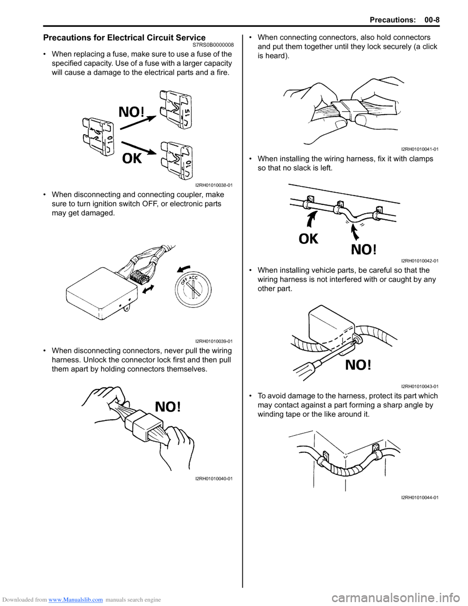
• When replacing a fuse, make sure to use a fuse of the specified capacity. Use of a fuse with a larger capacity
will cause a damage to the electrical parts and a fire.
• When disconnecting and connecting coupler, make sure to turn ignition switch OFF, or electronic parts
may get damaged.
• When disconnecting connectors, never pull the wiring harness. Unlock the connecto r lock first and then pull
them apart by holding connectors themselves. • When connecting connectors, also hold connectors
and put them together until th ey lock securely (a click
is heard).
• When installing the wiring harness, fix it with clamps so that no slack is left.
• When installing vehicle parts, be careful so that the wiring harness is not interfered with or caught by any
other part.
• To avoid damage to the harnes s, protect its part which
may contact against a part forming a sharp angle by
winding tape or the like around it.
I2RH01010038-01
I2RH01010039-01
I2RH01010040-01
I2RH01010041-01
I2RH01010042-01
I2RH01010043-01
I2RH01010044-01
Page 688 of 1496
Downloaded from www.Manualslib.com manuals search engine 5A-44 Automatic Transmission/Transaxle:
DTC P0602: Control Module Programming ErrorS7RS0B5104048
System Description
Internal control module is installed in ECM.
DTC Detecting Condition and Trouble Area
DTC Confirmation Procedure 1) Connect scan tool to DLC with ignition switch turned OFF.
2) Clear DTC, pending DTC and freeze frame data by using scan tool.
3) Start engine and run it at idle if possible.
4) Check DTC.
DTC Troubleshooting
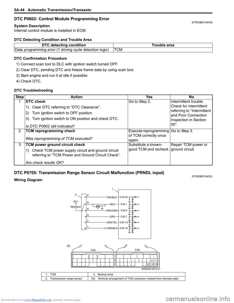
DTC P0705: Transmission Range Sensor Circuit Malfunction (PRNDL input)S7RS0B5104023
Wiring DiagramDTC detecting condition Trouble area
Data programming error (1 driving cycle detection logic) TCM
Step Action YesNo
1 DTC check
1) Clear DTC referring to “DTC Clearance”.
2) Turn ignition switch to OFF position.
3) Turn ignition switch to ON position and check DTC.
Is DTC P0602 still indicated? Go to Step 2.
Intermittent trouble.
Check for intermittent
referring to “Intermittent
and Poor Connection
Inspection in Section
00”.
2 TCM reprogramming check
Was reprogramming of TCM executed? Execute reprogramming
of TCM correctly once
again.Go to Step 3.
3 TCM power ground circuit check
1) Check TCM power supply circuit and ground circuit
referring to “TCM Power and Ground Circuit Check”.
Are check results OK? Substitute a known-
good TCM and recheck.
Repair TCM power or
ground circuit.
1. TCM
3. Backup lamp
2. Transmission range sensor [A]: Terminal arrangem ent of TCM connector (viewed from harness side)
2P
R
N
D 2 L 3
1
PNK/BLK
RED
GRN
GRN/ORN
GRN/YEL
IG11
RED/BLK
LT GRN/BLK
C35-20
C35-1
C35-8
C35-7
C35-19
C35-18
C34
20 19
87
18
1
C35
[A]
I4RS0A510010-01
Page 1212 of 1496
Downloaded from www.Manualslib.com manuals search engine 9A-41 Wiring Systems:
BCM (J/B side connector)
34
1
2 5
15
14
12
13
10
11
9
8
6
7
17
161821 22
19
20
23
1234578 11 6
12
91034 6 52
1
G33
G32
G34
10
11 12 13 14 15 16 17 18 19 123456789
20
345612K01
23414
3
561214
11
10 157
2113 16
98
6
5
4
3
2
1
7
11
10
9
8
15
14
13
12 16
L04
L06
E41
21
12 34 5 6 78 9
15 16 17 18
1110 12 13 14
1
234
5 678 910
E39
L05
E40
E39 E41E40
BCM G34G33G32K01 L04 L05 L06
11
J/B
Flasher Relay 78
2
5
1463
6
12
3
6
9
3
12
1
5
1
19
14
3
18
7
16
2
15
1
10
1Serial OUT
Serial INF DISP
HORN SW
HORN RELAY
GND SW-L SW-R
LP-LLP-R
IG
+B
HAZ HORN
SECURITY IN
ANSWER BACK HAZARD SW
METER (R)
FR TURN (R)
METER (L)
RR-TURN (R)
FR TURN (L) R-TURN (L)
TURN-R
TAIL SW
(HAZ, ASH,ILL) TURN-L
POSI LP TAIL LP,
LICENSE
TAIL BCM, WNG, etc
Lamp FL (FL BOX)
TAIL SW (Upper)
TAIL 10A
+B
D/L 20A
P/WT 20A D/L (+B)
32
(Continued)
Individual circuit fuse box No.2
(In J/B)
32
34
44
(Continued)
1
2
3
4
5
Connector No. / Terminal No.
2
18
I5RS0C910964-02
Page 1401 of 1496
Downloaded from www.Manualslib.com manuals search engine Table of Contents 10- i
10
Section 10
CONTENTS
Control Systems
Precautions ............................................... 10-1
Precautions........................................................... 10-1
Precautions for Control Systems......................... 10-1
Body Electrical Contro l System ........... 10B-1
Precautions......................................................... 10B-1
Precautions in Diagnosing Trouble ................... 10B-1
General Description ........................................... 10B-1 BCM General Description ................................. 10B-1
CAN Communication System Description......... 10B-2
Theft Deterrent Light ......................................... 10B-3
Security Alarm Description (If Equipped) .......... 10B-3
Schematic and Routing Diagram ...................... 10B-4 Body Electrical Control System Wiring Circuit Diagram .......................................................... 10B-4
Connector Layout Diagram of BCM and Junction Block Assembly ................................ 10B-7
Component Locatio n ......................................... 10B-8
BCM and Related System Component Location .......................................................... 10B-8
Diagnostic Information an d Procedures .......... 10B-9
BCM Self-Diagnosis Function ........................... 10B-9
Body Electrical Control System Check............ 10B-10
Scan Tool Data ............................................... 10B-12
DTC Table ....................................................... 10B-14
DTC Check ..................................................... 10B-14
DTC Clearance ............................................... 10B-15
BCM Power Circuit and Ground Circuit Check 10B-16
DTC B1133 (DTC No. 1133): Battery Voltage Too High ....................................................... 10B-17
DTC B1141 / DTC B1142 (No. 1141 / No. 1142): Outside Air Temperature (Ambient
Temp.) Sensor Circuit Ma lfunction ................ 10B-18
DTC B1150 (No. 1150): Air Bag Communication Circuit Malfunction .............. 10B-19
DTC B1157 (No. 1157): Air Bag Deployment Signal Input ................................................... 10B-20
DTC B1170 (No. 1170 ): EEPROM Access
Error .............................................................. 10B-21
DTC U0155 (No. 0155): Lost Communication with Instrument Panel Cluster (IPC) Control
Module .......................................................... 10B-21
DTC U1073 (No. 1073): Control Module Communication Bus Off ................................ 10B-24 DTC U1100 (No. 1100): Lost Communication
with ECM ....................................................... 10B-25
DTC U1101 (No. 1101): Lost Communication with TCM ....................................................... 10B-27
DTC U1144 (No. 1144): Lost Communication with Keyless Start Control Module ................ 10B-29
Inspection of BCM and its Circuits .................. 10B-31
Repair Instructions ........... ...............................10B-39
BCM (Included in Junction Block Assembly) Removal and Installation ............................... 10B-39
Outside Air Temperature Sensor Removal and Installation .............................................. 10B-39
Outside Air Temperature Sensor Inspection ... 10B-39
Security Alarm Mode Selection Procedure (If Equipped) ...................................................... 10B-39
Special Tools and Equipmen t .........................10B-40
Special Tool .................................................... 10B-40
Immobilizer Control Syst em ................. 10C-1
Precautions.........................................................10C-1
Precautions in Diagnosing Troubles .................10C-1
Precaution in Replacing ECM ...........................10C-1
Precautions in Handli ng Immobilizer Control
System ............................................................10C-1
General Description ...........................................10C-2 Immobilizer Control System Introduction ..........10C-2
Immobilizer Control System Components Location...........................................................10C-3
On-Board Diagnostic System Description (Self-diagnosis Function) ................................10C-3
Schematic and Routing Diag ram ......................10C-4
Immobilizer Control System Wiring Circuit Diagram...........................................................10C-4
Diagnostic Information an d Procedures ..........10C-5
Immobilizer Control System Check ...................10C-5
Diagnostic Trouble Code (DTC) Check.............10C-5
Diagnostic Trouble Code (DTC) Clearance ......10C-6
Diagnostic Trouble Code (DTC) Table ..............10C-6
Scan Tool Data .................................................10C-7
Immobilizer Indicator Lamp Does Not Come ON with Ignition Switch ON and Engine Stop ..10C-7
Immobilizer Indicator Lamp Remains ON after Engine Starts...................................................10C-8
DTC P1614: Transponder Re sponse Error .......10C-9
Page 1442 of 1496
Downloaded from www.Manualslib.com manuals search engine 10B-39 Body Electrical Control System:
Repair Instructions
BCM (Included in Junction Block Assembly)
Removal and Installation
S7RS0BA206001
CAUTION!
Do not attempt removal of BCM from junction
block assembly as it may cause contact
failure.
If there is faulty condition in BCM, replace
junction block assembly.
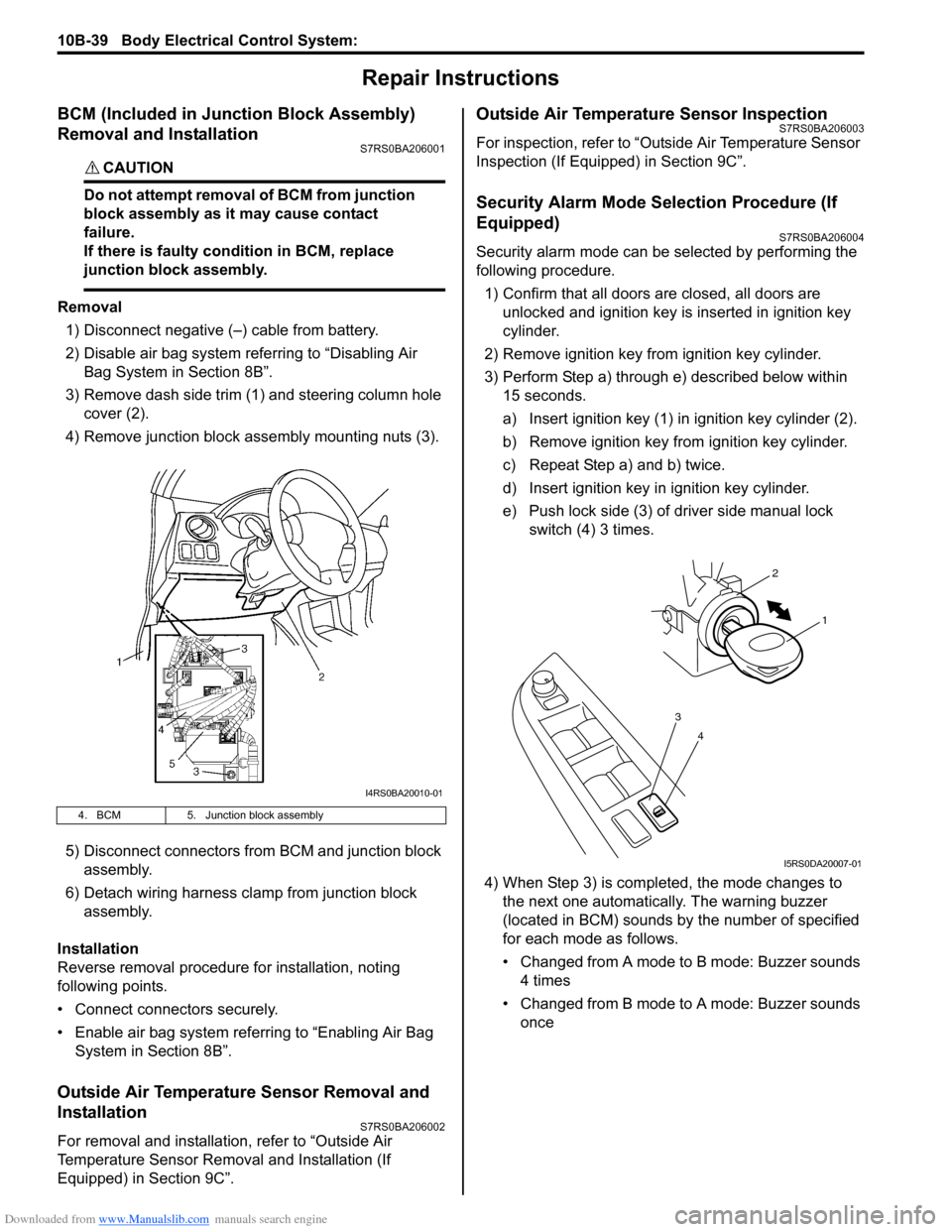
Removal
1) Disconnect negative (–) cable from battery.
2) Disable air bag system referring to “Disabling Air Bag System in Section 8B”.
3) Remove dash side trim (1) and steering column hole cover (2).
4) Remove junction block assembly mounting nuts (3).
5) Disconnect connectors from BCM and junction block assembly.
6) Detach wiring harness clamp from junction block assembly.
Installation
Reverse removal procedure for installation, noting
following points.
• Connect connectors securely.
• Enable air bag system referring to “Enabling Air Bag System in Section 8B”.
Outside Air Temperature Sensor Removal and
Installation
S7RS0BA206002
For removal and installation, refer to “Outside Air
Temperature Sensor Removal and Installation (If
Equipped) in Section 9C”.
Outside Air Temperature Sensor InspectionS7RS0BA206003
For inspection, refer to “Outside Air Temperature Sensor
Inspection (If Equipped) in Section 9C”.
Security Alarm Mode Selection Procedure (If
Equipped)
S7RS0BA206004
Security alarm mode can be selected by performing the
following procedure.
1) Confirm that all doors are closed, all doors are unlocked and ignition key is inserted in ignition key
cylinder.
2) Remove ignition key from ignition key cylinder.
3) Perform Step a) through e) described below within 15 seconds.
a) Insert ignition key (1) in ignition key cylinder (2).
b) Remove ignition key from ignition key cylinder.
c) Repeat Step a) and b) twice.
d) Insert ignition key in ignition key cylinder.
e) Push lock side (3) of driver side manual lock switch (4) 3 times.
4) When Step 3) is completed, the mode changes to the next one automatically. The warning buzzer
(located in BCM) sounds by the number of specified
for each mode as follows.
• Changed from A mode to B mode: Buzzer sounds 4 times
• Changed from B mode to A mode: Buzzer sounds once
4. BCM 5. Junction block assembly
I4RS0BA20010-01
4
3
1
2
I5RS0DA20007-01