Fuel ron SUZUKI SWIFT 2007 2.G Service Workshop Manual
[x] Cancel search | Manufacturer: SUZUKI, Model Year: 2007, Model line: SWIFT, Model: SUZUKI SWIFT 2007 2.GPages: 1496, PDF Size: 34.44 MB
Page 4 of 1496

Downloaded from www.Manualslib.com manuals search engine 00
0
1
2
3
4
5
6
7
8
9
10
11
Vo l u m e 1
Precautions............................................................... 00-iPrecautions ............................................................ 00-1
General Information ................ ................................... 0-i
General Information ............................................... 0A-1
Maintenance and Lubricatio n ................................. 0B-1
Engine ......................................................................... 1-i Precautions .............................................................. 1-1
Engine General Information and Diagnosis ........... 1A-1
Aux. Emission Control Devices .............................. 1B-1
Engine Electrical Devices....................................... 1C-1
Engine Mechanical ................................................. 1D-1
Engine Lubrication System .................................... 1E-1
Engine Cooling System .......................................... 1F-1
Fuel System ...........................................................1G-1
Ignition System....................................................... 1H-1
Starting System ....................................................... 1I-1
Charging System.....................................................1J-1
Exhaust System ..................................................... 1K-1
Suspension ................................................................. 2-i Precautions .............................................................. 2-1
Suspension General Diagnosis .............................. 2A-1
Front Suspension ................................................... 2B-1
Rear Suspension................ .................................... 2C-1
Wheels and Tires ................................................... 2D-1
Driveline / Axle ........................................................... 3-i Precautions .............................................................. 3-1
Drive Shaft / Axle ................................................... 3A-1
Brakes ......................................................................... 4-i Precautions .............................................................. 4-1
Brake Control System and Diagnosis .................... 4A-1
Front Brakes........................................................... 4B-1
Rear Brakes ........................................................... 4C-1
Parking Brake......................................................... 4D-1
ABS ........................................................................ 4E-1
Electronic Stability Program ................................... 4F-1
Vo l u m e 2
Precautions ............................................................... 00-iPrecautions ............................................................ 00-1
Transmission / Transaxle .... ...................................... 5-i
Precautions .............................................................. 5-1
Automatic Transmission/Transaxle ........................ 5A-1
Manual Transmission/Transaxle ............................ 5B-1
Clutch .....................................................................5C-1
Steering ....................................................................... 6-i Precautions .............................................................. 6-1
Steering General Diagnosis ................................... 6A-1
Steering Wheel and Column .................................. 6B-1
Power Assisted Steering System ...........................6C-1
HVAC ........................................................................... 7-i Precautions .............................................................. 7-1
Heater and Ventilation............................................ 7A-1
Air Conditioning System ......................................... 7B-1
Restraint ...................................................................... 8-i Precautions .............................................................. 8-1
Seat Belts ............................................................... 8A-1
Air Bag System ...................................................... 8B-1
Body, Cab and Accessories .... .................................. 9-i
Precautions .............................................................. 9-1
Wiring Systems ...................................................... 9A-1
Lighting Systems .................................................... 9B-1
Instrumentation / Driver Info. / Horn .......................9C-1
Wipers / Washers ...................................................9D-1
Glass / Windows / Mirrors ...................................... 9E-1
Security and Locks ................................................. 9F-1
Seats ..................................................................... 9G-1
Interior Trim ............................................................9H-1
Hood / Fenders / Doors .......................................... 9J-1
Body Structure ....................................................... 9K-1
Paint / Coatings ...................................................... 9L-1
Exterior Trim .......................................................... 9M-1
Control Systems ....................................................... 10-i Precautions ............................................................ 10-1
Body Electrical Control Sy stem ............................ 10B-1
Immobilizer Control System .................................10C-1
Keyless Start System ........................................... 10E-1
TABLE OF CONTENTS
Page 12 of 1496
Downloaded from www.Manualslib.com manuals search engine 00-7 Precautions:
Warning for Wheel (with tire) RemovalS7RS0B0000003
WARNING!
When removing any of these wheels installed
with wheel bolts, never remove all wheel
bolts at the same time. Leave at least 1 bolt
for each wheel as it is to prevent wheel from
dropping. When removing this remaining 1
bolt, hold wheel and tire so as not to allow
them to come off.
Warning for Handling Emergency Flat Tire
Repair Kit
S7RS0B0000004
WARNING!
If vehicle is equipped with Emergency Flat
Tire Repair Kit instead of spare tire, be sure
to observe “Precaution for Emergency Flat
Tire Repair Kit in Section 2D” when handling
Emergency Flat Tire Repair Kit and repairing
flat tire.
Otherwise, your health may be ruined or it
will be impossible to repair flat tire.
Precautions for Catalytic ConverterS7RS0B0000005
For vehicles equipped with a catalytic converter, use
only unleaded gasoline and be careful not to let a large
amount of unburned gasoline enter the converter or it
can be damaged.
• Conduct a spark jump test only when necessary, make it as short as possible, and do not open the
throttle.
• Conduct engine compression checks within the shortest possible time.
• Avoid situations which can result in engine misfire (e.g. starting the engine when the fuel tank is nearly
empty.)
Precautions for Installing Mobile
Communication Equipment
S7RS0B0000006
When installing mobile communication equipment such
as CB (Citizens-Band)-radi o or cellular-telephone, be
sure to observe the following precautions.
Failure to follow cautions may adversely affect electronic
control system.
• Keep the antenna as far away as possible from the vehicle’s electronic control unit.
• Keep the antenna feeder more than 20 cm (7.9 in.) away from electronic control unit and its wire
harnesses.
• Do not run the antenna feeder parallel with other wire harnesses.
• Confirm that the antenna and feeder are correctly adjusted.
Precaution for CAN Communication SystemS7RS0B0000007
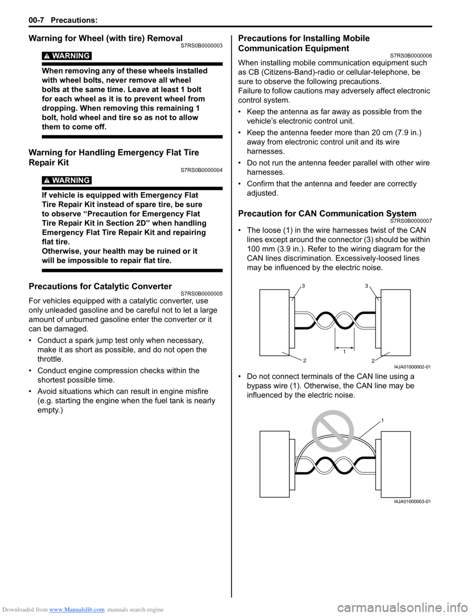
• The loose (1) in the wire harnesses twist of the CAN lines except around the connector (3) should be within
100 mm (3.9 in.). Refer to the wiring diagram for the
CAN lines discrimination. Excessively-loosed lines
may be influenced by the electric noise.
• Do not connect terminals of the CAN line using a bypass wire (1). Otherwise, the CAN line may be
influenced by the electric noise.
33
2
2
1
I4JA01000002-01
1
I4JA01000003-01
Page 22 of 1496
Downloaded from www.Manualslib.com manuals search engine 0A-1 General Information:
General Information
General Information
General Description
AbbreviationsS7RS0B0101001
A:
ABDC: After Bottom Dead Center
ABS: Anti-lock Brake System
AC: Alternating Current
A/C: Air Conditioning
A-ELR: Automatic-Emergency Locking Retractor
A/F: Air Fuel Mixture Ratio
ALR: Automatic Locking Retractor
API: American Petroleum Institute
APP sensor: Accelerator Pedal Position Sensor
A/T: Automatic Transmission , Automatic Transaxle
AT D C : After Top Dead Center
ATF: Automatic Transmission Fluid, Automatic
Transaxle Fluid
B:
B+: Battery Positive Voltage
BBDC: Before Bottom Dead Center
BCM: Body Electrical Control Module
BDC: Bottom Dead Center
BTDC: Before Top Dead Center
C:
CAN: Controller Area Network
CKT: Circuit
CKP Sensor: Crankshaft Position Sensor
CMP Sensor: Camshaft Position Sensor
CO: Carbon Monoxide
CPP Switch: Clutch Pedal Position Switch (Clutch
Switch, Clutch Start Switch)
CPU: Central Processing Unit
CRS: Child Restraint System
D:
DC: Direct Current
DLC: Data Link Connector (Assembly Line Diag. Link,
ALDL, Serial Data Link, SDL)
DOHC: Double Over Head Camshaft
DOJ: Double Offset Joint
DRL: Daytime Running Light
DTC: Diagnostic Trouble Code (Diagnostic Code)
E:
EBCM: Electronic Brake Cont rol Module, ABS Control
Module
EBD: Electronic Brake Force Distribution
ECM: Engine Control Module
ECT Sensor: Engine Coolant Temperature Sensor (Water Temp. Sensor, WTS)
EFE Heater: Early Fuel Evaporation Heater (Positive
Temperature Coefficient, PTC Heater)
EGR: Exhaust Gas Recirculation
EGRT Sensor: EGR Temperature Sensor (Recirculated
Exhaust Gas Temp. Sensor, REGTS)
ELR: Emergency Locking Retractor
ESP ®: Electronic Stability Program
EPS: Electronic Power Steering
EVAP: Evaporative Emission EVAP Canister:
Evaporative Emission Canister
(Charcoal Canister)
F:
4WD: 4 Wheel
Drive
G:
GEN: Generator
GND: Ground
GPS: Global Positioning System
H:
HVAC: Heating, Ventilating and Air Conditioning
HC: Hydrocarbons
HO2S: Heated Oxygen Sensor
I:
IAC Valve: Idle Air Control Valve (Idle Speed Control
Solenoid Valve, ISC Solenoid Valve)
IAT Sensor: Intake Air Temperature Sensor (Air
temperature Sensor, ATS)
ICM: Immobilizer Control Module
IG: Ignition
ISC Actuator: Idle Speed Control Actuator
L:
LH: Left Hand
LHD: Left Hand Drive Vehicle
LSPV: Load Sensing Proportioning Valve
M:
MAF Sensor: Mass Air Flow Sensor (Air Flow Sensor, AFS, Air Flow Meter, AFM)
MAP Sensor: Manifold Absolute Pressure Sensor
(Pressure Sensor, PS)
Max: Maximum
MFI: Multiport Fuel Injection (Mu ltipoint Fuel Injection)
Min: Minimum
MIL: Malfunction Indicator Lamp (“SERVICE ENGINE
SOON” Light)
M/T: Manual Transmission, Manual Transaxle
N:
NOx: Nitrogen Oxides
O:
OBD: On-Board Diagnostic System (Self-Diagnosis
Function)
O/D: Overdrive
OHC: Over Head Camshaft
O2S: Oxygen Sensor
P:
PCM: Powertrain Control Module
PCV: Positive Crankcase Ventilation
PNP: Park / Neutral Position
P/S: Power Steering
PSP Switch: Power Steering Pressure Switch (P/S
Pressure Switch)
R:
RH: Right Hand
RHD: Right Hand Drive Vehicle
S:
SAE: Society of Automotive Engineers
Page 26 of 1496
Downloaded from www.Manualslib.com manuals search engine 0A-5 General Information:
Vehicle Lifting PointsS7RS0B0101005
WARNING!
• Before applying hoist to underbody, always take vehicle balance throughout service into
consideration. Vehicle balance on hoist may change depending on what part to be removed.
• Before lifting up the vehicle, check to be sure that end of hoist arm is not in contact with brake pipe,
fuel pipe, bracket or any other part.
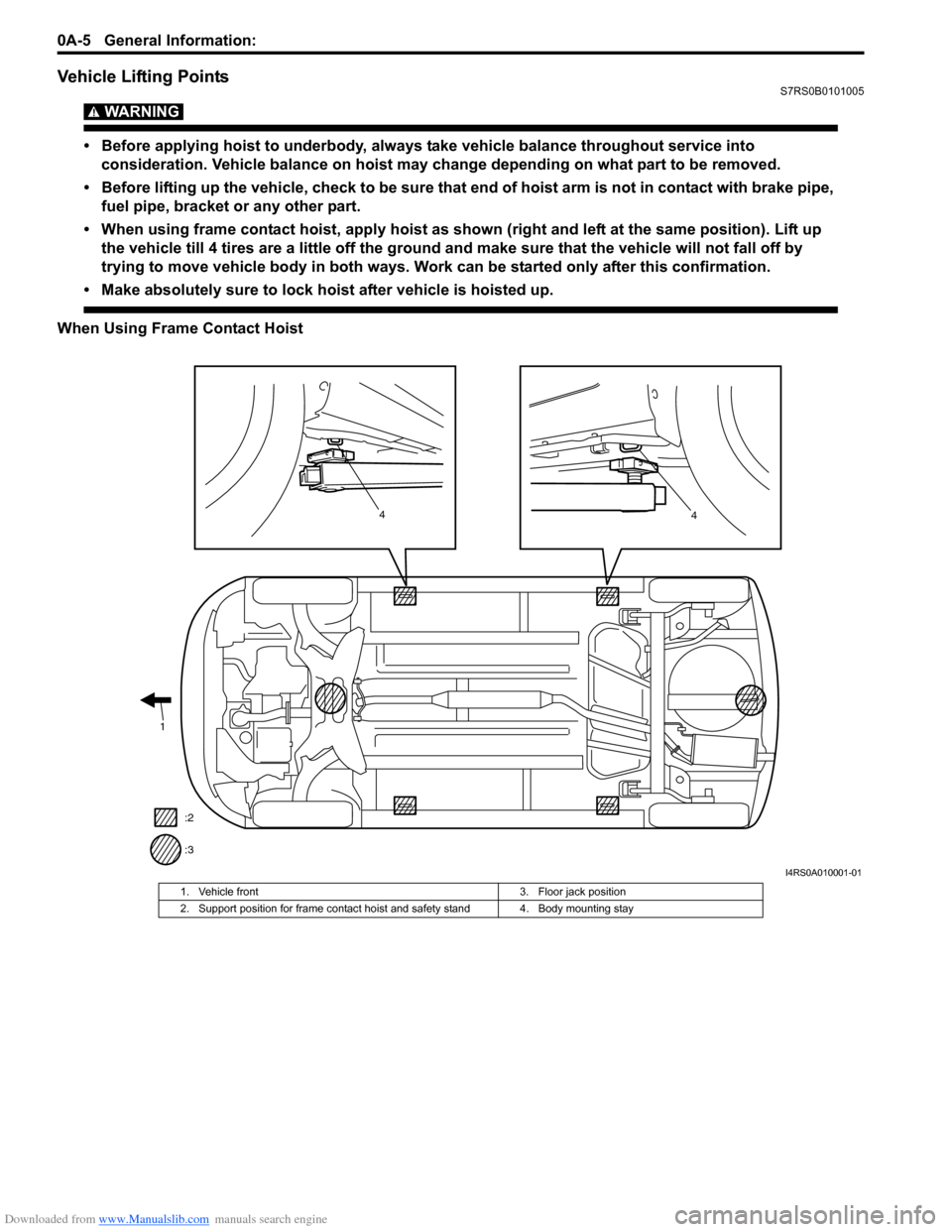
• When using frame contact hoist, apply hoist as shown (right and left at the same position). Lift up
the vehicle till 4 tires are a little off the ground and make sure that the vehicle will not fall off by
trying to move vehicle body in both ways. Work can be started only after this confirmation.
• Make absolutely sure to lock hoist after vehicle is hoisted up.
When Using Frame Contact Hoist
1
:2
:3
4
4
I4RS0A010001-01
1. Vehicle front
3. Floor jack position
2. Support position for frame contact hoist and safety stand 4. Body mounting stay
Page 37 of 1496
Downloaded from www.Manualslib.com manuals search engine Maintenance and Lubrication: 0B-7
Fuel Filter ReplacementS7RS0B0206011
Fuel filter is installed in fuel pump assembly in fuel tank.
Replace fuel filter or fuel pump assembly with new one,
referring to “Fuel Pump Assembly Removal and
Installation in Section 1G” for proper procedure.
Fuel Tank InspectionS7RS0B0206012
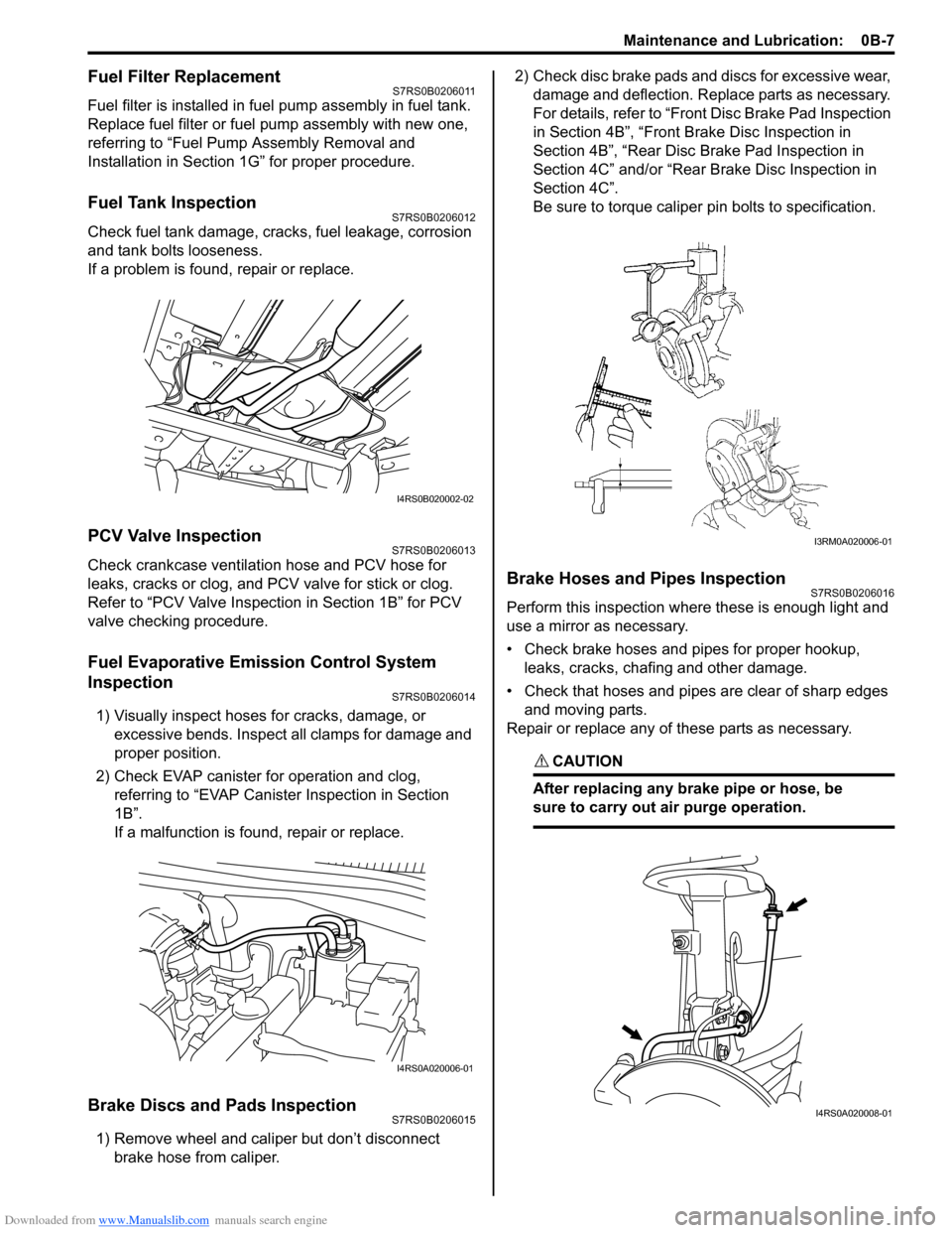
Check fuel tank damage, cracks, fuel leakage, corrosion
and tank bolts looseness.
If a problem is found, repair or replace.
PCV Valve InspectionS7RS0B0206013
Check crankcase ventilation hose and PCV hose for
leaks, cracks or clog, and PCV valve for stick or clog.
Refer to “PCV Valve Inspection in Section 1B” for PCV
valve checking procedure.
Fuel Evaporative Emission Control System
Inspection
S7RS0B0206014
1) Visually inspect hoses for cracks, damage, or excessive bends. Inspect a ll clamps for damage and
proper position.
2) Check EVAP canister for operation and clog, referring to “EVAP Canister Inspection in Section
1B”.
If a malfunction is found, repair or replace.
Brake Discs and Pads InspectionS7RS0B0206015
1) Remove wheel and caliper but don’t disconnect brake hose from caliper. 2) Check disc brake pads and discs for excessive wear,
damage and deflection. Replace parts as necessary.
For details, refer to “Front Disc Brake Pad Inspection
in Section 4B”, “Front Brake Disc Inspection in
Section 4B”, “Rear Disc Brake Pad Inspection in
Section 4C” and/or “Rear Brake Disc Inspection in
Section 4C”.
Be sure to torque caliper pin bolts to specification.
Brake Hoses and Pipes InspectionS7RS0B0206016
Perform this inspection where these is enough light and
use a mirror as necessary.
• Check brake hoses and pipes for proper hookup, leaks, cracks, chafing and other damage.
• Check that hoses and pipes are clear of sharp edges and moving parts.
Repair or replace any of these parts as necessary.
CAUTION!
After replacing any brake pipe or hose, be
sure to carry out air purge operation.
I4RS0B020002-02
I4RS0A020006-01
I3RM0A020006-01
I4RS0A020008-01
Page 45 of 1496
Downloaded from www.Manualslib.com manuals search engine Table of Contents 1- i
1
Section 1
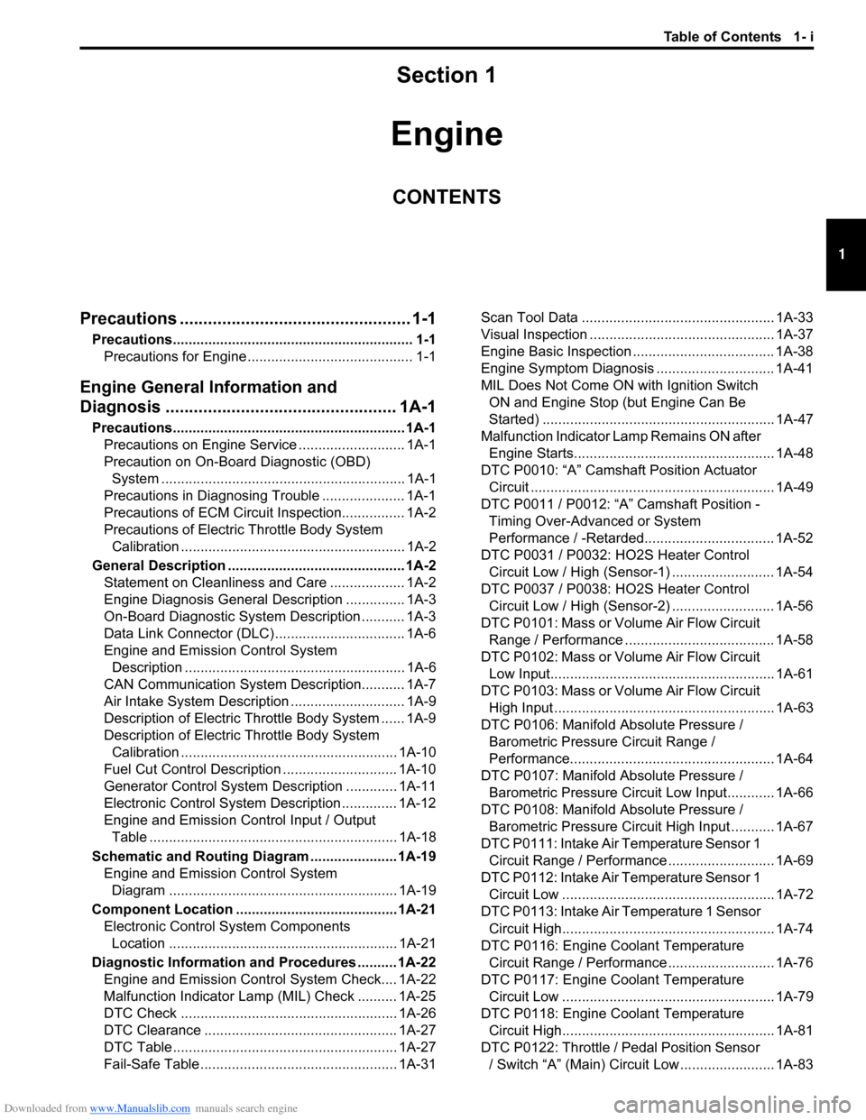
CONTENTS
Engine
Precautions ................................................. 1-1
Precautions............................................................. 1-1
Precautions for Engine .......................................... 1-1
Engine General Information and
Diagnosis ............. .................................... 1A-1
Precautions........................................................... 1A-1
Precautions on Engine Service ........................... 1A-1
Precaution on On-Board Diagnostic (OBD) System .............................................................. 1A-1
Precautions in Diagnosing Trouble ..................... 1A-1
Precautions of ECM Circuit Inspection................ 1A-2
Precautions of Electric Throttle Body System
Calibration ......................................................... 1A-2
General Description ............................................. 1A-2 Statement on Cleanliness and Care ................... 1A-2
Engine Diagnosis General Description ............... 1A-3
On-Board Diagnostic System Description ........... 1A-3
Data Link Connector (DLC) ................................. 1A-6
Engine and Emission Control System Description ........................................................ 1A-6
CAN Communication System Description........... 1A-7
Air Intake System Description ............................. 1A-9
Description of Electric Throttle Body System ...... 1A-9
Description of Electric Throttle Body System Calibration ....................................................... 1A-10
Fuel Cut Control Description ............................. 1A-10
Generator Control System Description ............. 1A-11
Electronic Control System Description .............. 1A-12
Engine and Emission Control Input / Output Table ............................................................... 1A-18
Schematic and Routing Diagram ...................... 1A-19 Engine and Emission Control System Diagram .......................................................... 1A-19
Component Locatio n ......................................... 1A-21
Electronic Control System Components Location .......................................................... 1A-21
Diagnostic Information and Procedures .......... 1A-22 Engine and Emission Control System Check.... 1A-22
Malfunction Indicator Lamp (MIL) Check .......... 1A-25
DTC Check ....................................................... 1A-26
DTC Clearance ................................................. 1A-27
DTC Table ......................................................... 1A-27
Fail-Safe Table ................ .................................. 1A-31 Scan Tool Data ................................................. 1A-33
Visual Inspection ............................................... 1A-37
Engine Basic Inspection .................................... 1A-38
Engine Symptom Diagnosis .............................. 1A-41
MIL Does Not Come ON with Ignition Switch
ON and Engine Stop (but Engine Can Be
Started) ........................................................... 1A-47
Malfunction Indicator Lamp Remains ON after Engine Starts................................................... 1A-48
DTC P0010: “A” Camshaft Position Actuator Circuit .............................................................. 1A-49
DTC P0011 / P0012: “A” Camshaft Position - Timing Over-Advanced or System
Performance / -Retarded................................. 1A-52
DTC P0031 / P0032: HO2S Heater Control Circuit Low / High (Sensor-1) .......................... 1A-54
DTC P0037 / P0038: HO2S Heater Control Circuit Low / High (Sensor-2) .......................... 1A-56
DTC P0101: Mass or Volume Air Flow Circuit Range / Performance ...................................... 1A-58
DTC P0102: Mass or Volume Air Flow Circuit Low Input......................................................... 1A-61
DTC P0103: Mass or Volume Air Flow Circuit High Input ........................................................ 1A-63
DTC P0106: Manifold Absolute Pressure /
Barometric Pressure Circuit Range /
Performance.................................................... 1A-64
DTC P0107: Manifold Absolute Pressure /
Barometric Pressure Circ uit Low Input............ 1A-66
DTC P0108: Manifold Absolute Pressure /
Barometric Pressure Circ uit High Input ........... 1A-67
DTC P0111: Intake Air Temperature Sensor 1 Circuit Range / Performance ........................... 1A-69
DTC P0112: Intake Air Temperature Sensor 1 Circuit Low ...................................................... 1A-72
DTC P0113: Intake Air Temperature 1 Sensor Circuit High...................................................... 1A-74
DTC P0116: Engine Coolant Temperature Circuit Range / Performance ........................... 1A-76
DTC P0117: Engine Coolant Temperature Circuit Low ...................................................... 1A-79
DTC P0118: Engine Coolant Temperature Circuit High...................................................... 1A-81
DTC P0122: Throttle / Pedal Position Sensor / Switch “A” (Main) Circuit Low ........................ 1A-83
Page 56 of 1496
Downloaded from www.Manualslib.com manuals search engine 1A-6 Engine General Information and Diagnosis:
For information about the following items, refer to “Euro
OBD Model: ”.
• Warm-up cycle
• Driving cycle
• 2 driving cycle detection logic
• Pending DTC
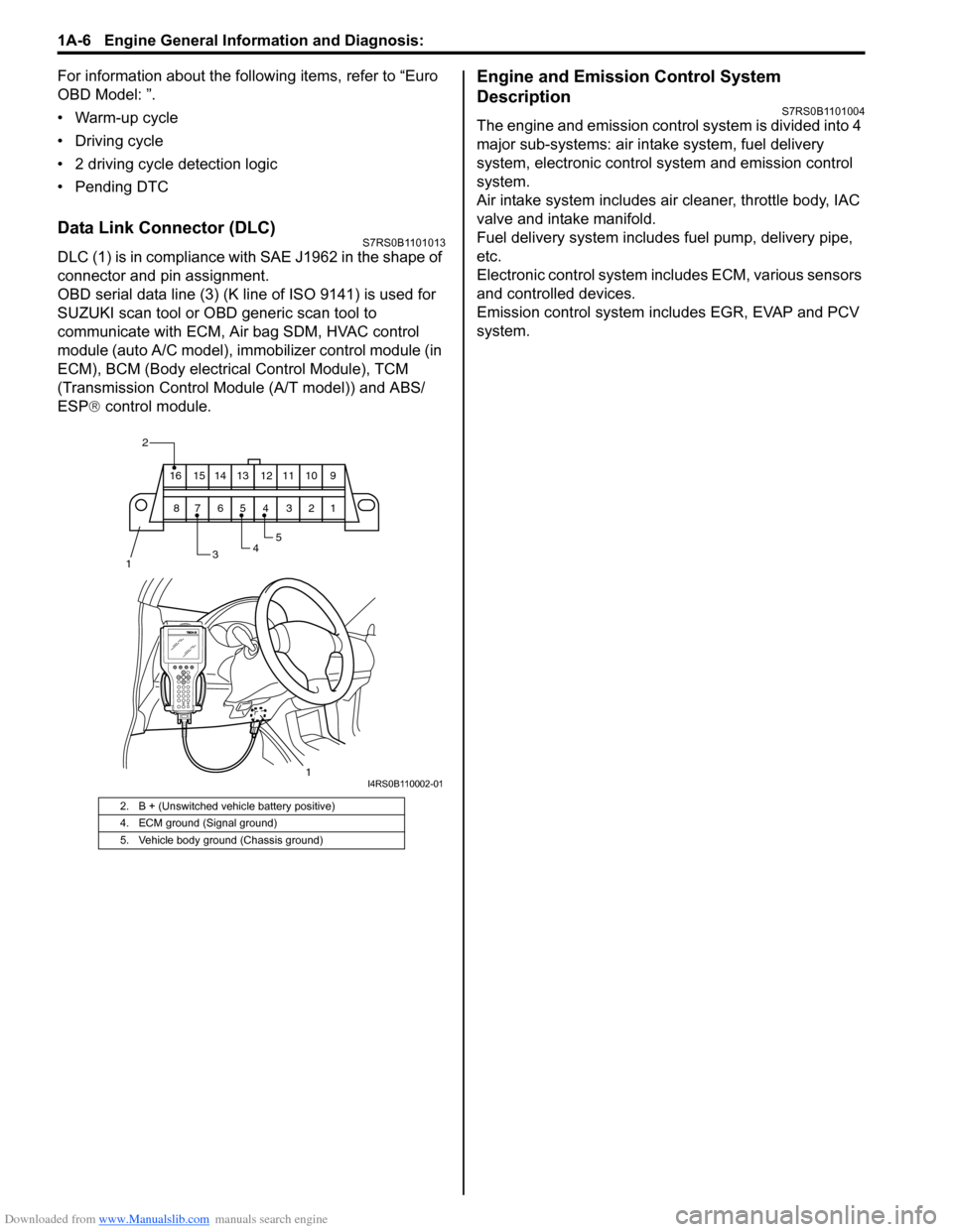
Data Link Connector (DLC)S7RS0B1101013
DLC (1) is in compliance with SAE J1962 in the shape of
connector and pin assignment.
OBD serial data line (3) (K line of ISO 9141) is used for
SUZUKI scan tool or OBD generic scan tool to
communicate with ECM, Air bag SDM, HVAC control
module (auto A/C model), immobilizer control module (in
ECM), BCM (Body electrical Control Module), TCM
(Transmission Cont rol Module (A/T model)) and ABS/
ESP ® control module.
Engine and Emission Control System
Description
S7RS0B1101004
The engine and emission control system is divided into 4
major sub-systems: air in take system, fuel delivery
system, electronic control sy stem and emission control
system.
Air intake system includes air cleaner, throttle body, IAC
valve and intake manifold.
Fuel delivery system includes fuel pump, delivery pipe,
etc.
Electronic control system incl udes ECM, various sensors
and controlled devices.
Emission control system includes EGR, EVAP and PCV
system.
2. B + (Unswitched vehicle battery positive)
4. ECM ground (Signal ground)
5. Vehicle body ground (Chassis ground)
2
345
1
910111213141516
12345678
1I4RS0B110002-01
Page 58 of 1496
Downloaded from www.Manualslib.com manuals search engine 1A-8 Engine General Information and Diagnosis:
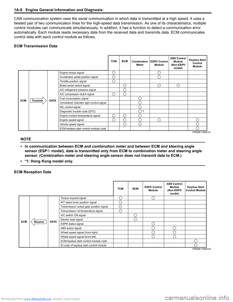
CAN communication system uses the serial communication in which data is transmitted at a high speed. It uses a
twisted pair of two communication lines for the high-speed da ta transmission. As one of its characteristics, multiple
control modules can communicate simultaneously. In addition, it has a function to detect a communication error
automatically. Each module reads necessary data from the received data and transmits data. ECM communicates
control data with each control module as follows.
ECM Transmission Data
NOTE
• In communication between ECM and combination meter and between ECM and steering angle sensor (ESP ® model), data is transmitted only from ECM to combination meter and steering angle
sensor. (Combination meter and steering angle sensor does not transmit data to ECM.)
• *1: Hong Kong model only.
ECM Reception Data
Engine torque signal
Accelerator pedal position signal
Throttle position signal
Brake pedal switch signal
A/C refrigerant pressure signal
A/C compressor clutch signal
Fuel consumption signal
Immobilizer indicator light control signal
MIL control signal
Diagnostic trouble code (DTC)
Engine coolant temperature signal
Engine speed signal
Vehicle speed signal
ECM-keyless start control module code TCM BCM
Combination
Meter Keyless Start
ControlModule
Transmit DATA
ECM
ESP® Control
Module ABS Control
Module
(Non-ESP® model)
*1
I7RS0B110002-01
TCM BCM Keyless Start
Control Module
DATA
ECM
Torque request signal
A/T select lever position signal
Transmission actual gear position signal
Transmission oil temperature signal
A/C switch ON signal
Electric load signal
ESP® status signal
ABS active signal
Wheel speed signal (front right)
Wheel speed signal (front left)
ECM-keyless start control module code
ID code of keyless start control module
Receive
ABS Control
Module
(Non-ESP® model)
ESP® Control
Module
I7RS0B110003-02
Page 62 of 1496
Downloaded from www.Manualslib.com manuals search engine 1A-12 Engine General Information and Diagnosis:
Electronic Control System DescriptionS7RS0B1101011
The electronic control system consists of 1) various sensors which detect the state of engine and driving conditions, 2)
ECM which controls various devices ac cording to the signals from the sensors and 3) various controlled devices.
Functionally, it is divided into the following sub systems:
• Fuel injection control system
• Ignition control system
• Electric throttle body control system
• Fuel pump control system
• Radiator cooling fan control system
• Evaporative emission control system
• EGR system
• Oxygen sensor heater control system
• A/C control system (A/C model)
• Camshaft position control system
• Immobilizer control system
• Generator control system
• Controller (computer) communication system
Especially, ECM, BCM, combination meter, TCM (A/T model), ABS/ESP ® control module, steering angle sensor
(ESP® model) and keyless start control module (if equipped) intercommunicate by means of CAN communication.
Page 71 of 1496
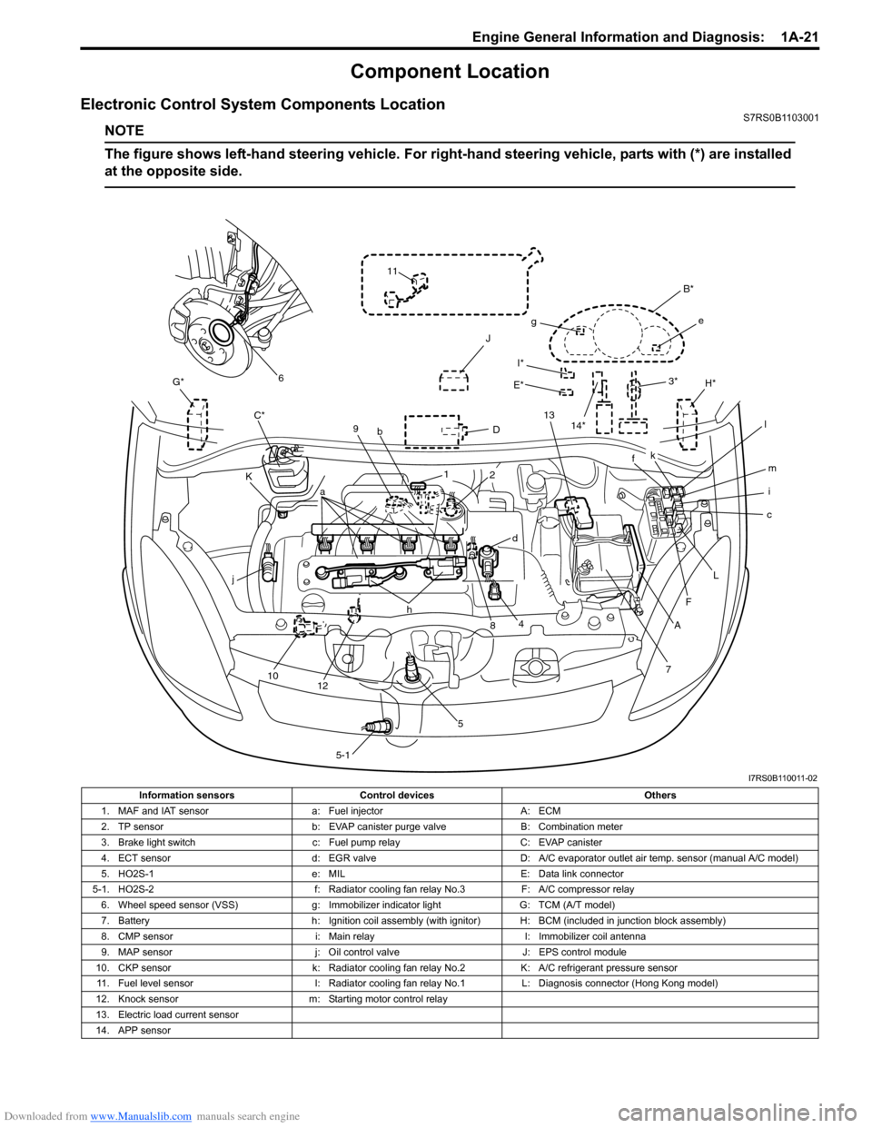
Downloaded from www.Manualslib.com manuals search engine Engine General Information and Diagnosis: 1A-21
Component Location
Electronic Control System Components LocationS7RS0B1103001
NOTE
The figure shows left-hand steering vehicle. For right-hand steering vehicle, parts with (*) are installed
at the opposite side.
I*
E*
G*
D
K H*
J
C*
7
A
F
c
L
i m
f
B*
e
g
k
l
13
3*
4
j
10 12 h
58
a
9
b
1
5-1
d
2
11
6
14*
I7RS0B110011-02
Information sensors Control devices Others
1. MAF and IAT sensor a: Fuel injectorA: ECM
2. TP sensor b: EVAP canister purge valve B: Combination meter
3. Brake light switch c: Fuel pump relayC: EVAP canister
4. ECT sensor d: EGR valveD: A/C evaporator outlet air temp. sensor (manual A/C model)
5. HO2S-1 e: MILE: Data link connector
5-1. HO2S-2 f: Radiator cooling fan relay No.3F: A/C compressor relay
6. Wheel speed sensor (VSS) g: Immobilizer indicator lightG: TCM (A/T model)
7. Battery h: Ignition coil assembly (with ignitor) H: BCM (included in junction block assembly)
8. CMP sensor i: Main relayI: Immobilizer coil antenna
9. MAP sensor j: Oil control valveJ: EPS control module
10. CKP sensor k: Radiator cooling fan relay No.2K: A/C refrigerant pressure sensor
11. Fuel level sensor l: Radiator cooling fan relay No.1L: Diagnosis connector (Hong Kong model)
12. Knock sensor m: Starting motor control relay
13. Electric load current sensor
14. APP sensor