Ig coil relay SUZUKI SWIFT 2007 2.G Service Workshop Manual
[x] Cancel search | Manufacturer: SUZUKI, Model Year: 2007, Model line: SWIFT, Model: SUZUKI SWIFT 2007 2.GPages: 1496, PDF Size: 34.44 MB
Page 46 of 1496
Downloaded from www.Manualslib.com manuals search engine 1-ii Table of Contents
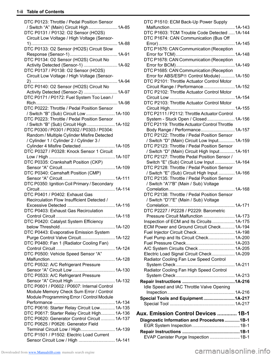
DTC P0123: Throttle / Pedal Position Sensor / Switch “A” (Main) Circuit High ....................... 1A-85
DTC P0131 / P0132: O2 Sensor (HO2S) Circuit Low Voltage / High Voltage (Sensor-
1) ..................................................................... 1A-88
DTC P0133: O2 Sensor (HO2S) Circuit Slow
Response (Sensor- 1) ...................................... 1A-91
DTC P0134: O2 Sensor (HO2S) Circuit No Activity Detected (Sensor -1) ........................... 1A-92
DTC P0137 / P0138: O2 Sensor (HO2S) Circuit Low Voltage / High Voltage (Sensor-
2) ..................................................................... 1A-94
DTC P0140: O2 Sensor (HO2S) Circuit No Activity Detected (Sensor -2) ........................... 1A-97
DTC P0171 / P0172: Fuel System Too Lean / Rich ................................................................. 1A-98
DTC P0222: Throttle / Pedal Position Sensor / Switch “B” (Sub) Circuit Low ....................... 1A-100
DTC P0223: Throttle / Pedal Position Sensor / Switch “B” (Sub) Circuit High ...................... 1A-102
DTC P0300 / P0301 / P0302 / P0303 / P0304: Random / Multiple Cylin der Misfire Detected
/ Cylinder 1 / Cylinder 2 / Cylinder 3 /
Cylinder 4 Misfire Detected ........................... 1A-105
DTC P0327 / P0328: Knoc k Sensor 1 Circuit
Low / High ..................................................... 1A-107
DTC P0335: Crankshaft Position (CKP) Sensor “A” Circuit .......................................... 1A-109
DTC P0340: Camshaft Position (CMP) Sensor “A” Circuit .......................................... 1A-111
DTC P0350: Ignition Coil Primary / Secondary Circuit ............................................................ 1A-114
DTC P0401 / P0402: Exhaust Gas Recirculation Flow Insufficient Detected /
Excessive Detected ...................................... 1A-116
DTC P0403: Exhaust Gas Recirculation Control Circuit ................... ............................ 1A-118
DTC P0420: Catalyst System Efficiency
below Threshold ................ ............................ 1A-120
DTC P0443: Evaporativ e Emission System
Purge Control Valve Circuit ........................... 1A-122
DTC P0480: Fan 1 (Radiator Cooling Fan) Control Circuit ................... ............................ 1A-124
DTC P0500: Vehicle Speed Sensor “A” Malfunction .................................................... 1A-128
DTC P0532: A/C Refrigerant Pressure Sensor “A” Circuit Low ... ............................... 1A-130
DTC P0533: A/C Refrigerant Pressure Sensor “A” Circuit High ................................. 1A-132
DTC P0601 / P0602 / P0607: Internal Control Module Memory Check Sum Error / Control
Module Programming Error / Control Module
Performance ................................................. 1A-134
DTC P0616: Starter Relay Circuit Low............ 1A-135
DTC P0617: Starter Relay Circuit High ........... 1A-136
DTC P0620: Generator Control Circuit ........... 1A-137
DTC P0625 / P0626: Generator Field Terminal Circuit Low / High . .......................... 1A-139
DTC P1501 / P1502: Electric Load Current Sensor Circuit Low / High . ............................ 1A-141 DTC P1510: ECM Back-Up Power Supply
Malfunction .................................................... 1A-143
DTC P1603: TCM Trouble Code Detected ..... 1A-144
DTC P1674: CAN Communication (Bus Off Error) ............................................................. 1A-145
DTC P1676: CAN Communication (Reception Error for TCM) ............................................... 1A-148
DTC P1678: CAN Communication (Reception Error for BCM) ............................................... 1A-149
DTC P1685: CAN Communication (Reception Error for ABS/ESP ® Control Module) ........... 1A-150
DTC P2101: Throttle Actuator Control Motor Circuit Range / Performance ......................... 1A-152
DTC P2102: Throttle Actuator Control Motor Circuit Low .................................................... 1A-154
DTC P2103: Throttle Actuator Control Motor Circuit High.................................................... 1A-155
DTC P2111 / P2112: Throttle Actuator Control System - Stuck Open / Closed ...................... 1A-156
DTC P2119: Throttle Actu ator Control Throttle
Body Range / Performance ........................... 1A-157
DTC P2122: Throttle / Pedal Position Sensor / Switch “D” (Main) Circuit Low Input............. 1A-159
DTC P2123: Throttle / Pedal Position Sensor / Switch “D” (Main) Circuit High Input ............ 1A-161
DTC P2127: Throttle Pedal Position Sensor / Switch “E” (Sub) Circuit Low Input ................ 1A-164
DTC P2128: Throttle / Pedal Position Sensor
/ Switc
h “E” (Sub) Circuit High Input ............. 1A-166
DTC P2135: Throttle / Pedal Position Sensor / Switch “A”/“B” (Main / Sub) Voltage
Correlation..................................................... 1A-168
DTC P2138: Throttle / Pedal Position Sensor / Switch “D”/“E” (Main / Sub) Voltage
Correlation..................................................... 1A-171
DTC P2227 / P2228 / P2229: Barometric Pressure Circuit Malfunction ......................... 1A-173
Inspection of ECM and Its Circuits .................. 1A-175
ECM Power and Ground Circuit Check........... 1A-194
Fuel Injector Circuit Check .............................. 1A-198
Fuel Pump and Its Circuit Check..................... 1A-200
Fuel Pressure Check....................................... 1A-203
A/C System Circuits Check ............................. 1A-205
Electric Load Signal Circuit Check .................. 1A-209
Radiator Cooling Fan Low Speed Control System Check ............................................... 1A-211
Radiator Cooling Fan High Speed Control System Check ............................................... 1A-213
Repair Instructions ......... .................................1A-216
Idle Speed and IAC Throttle Valve Opening Inspection ...................................................... 1A-216
Special Tools and Equipmen t .........................1A-217
Special Tool .................................................... 1A-217
Aux. Emission Control Devices ............. 1B-1
Diagnostic Information and Procedures ............1B-1
EGR System Inspection ...................................... 1B-1
Repair Instructions ............ ..................................1B-1
EVAP Canister Purge Inspec tion ........................ 1B-1
Page 55 of 1496
Downloaded from www.Manualslib.com manuals search engine Engine General Information and Diagnosis: 1A-5
Freeze frame data clearance:
The freeze frame data is cleared at the same time as
clearance of DTC.
Non-Euro-OBD
ECM diagnosis troubles which may occur in the area
including the following parts w hen the ignition switch is
ON and the engine is running, and indicates the result by
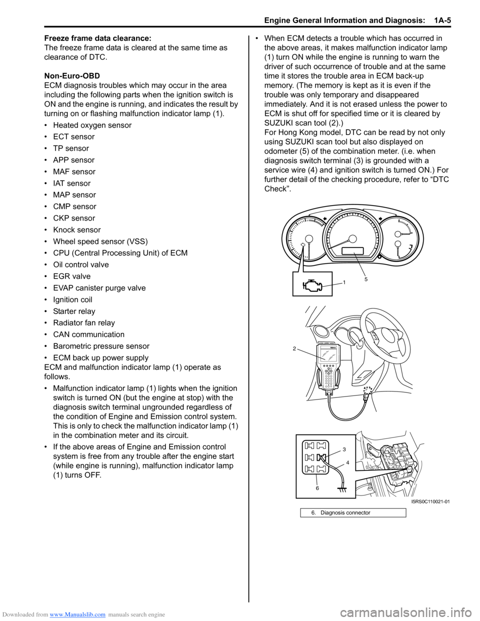
turning on or flashing malfunction indicator lamp (1).
• Heated oxygen sensor
• ECT sensor
•TP sensor
• APP sensor
• MAF sensor
• IAT sensor
• MAP sensor
• CMP sensor
• CKP sensor
• Knock sensor
• Wheel speed sensor (VSS)
• CPU (Central Processing Unit) of ECM
• Oil control valve
• EGR valve
• EVAP canister purge valve
• Ignition coil
• Starter relay
• Radiator fan relay
• CAN communication
• Barometric pressure sensor
• ECM back up power supply
ECM and malfunction indicator lamp (1) operate as
follows.
• Malfunction indicator lamp (1) lights when the ignition switch is turned ON (but t he engine at stop) with the
diagnosis switch terminal ungrounded regardless of
the condition of Engine and Emission control system.
This is only to check the ma lfunction indicator lamp (1)
in the combination meter and its circuit.
• If the above areas of Engine and Emission control system is free from any trouble after the engine start
(while engine is running), malfunction indicator lamp
(1) turns OFF. • When ECM detects a trouble which has occurred in
the above areas, it makes malfunction indicator lamp
(1) turn ON while the engi ne is running to warn the
driver of such occurrence of trouble and at the same
time it stores the trouble area in ECM back-up
memory. (The memory is kept as it is even if the
trouble was only temporary and disappeared
immediately. And it is not erased unless the power to
ECM is shut off for specified time or it is cleared by
SUZUKI scan tool (2).)
For Hong Kong model, DTC can be read by not only
using SUZUKI scan tool but also displayed on
odometer (5) of the combination meter. (i.e. when
diagnosis switch terminal (3) is grounded with a
service wire (4) and ignition switch is turned ON.) For
further detail of the checking procedure, refer to “DTC
Check”.
6. Diagnosis connector
2
1
6 3
5
4
I5RS0C110021-01
Page 65 of 1496
![SUZUKI SWIFT 2007 2.G Service Workshop Manual Downloaded from www.Manualslib.com manuals search engine Engine General Information and Diagnosis: 1A-15
Terminal Arrangement of ECM Coupler (Viewed from Harness Side)
[A]: Manual A/C model24. ABS / SUZUKI SWIFT 2007 2.G Service Workshop Manual Downloaded from www.Manualslib.com manuals search engine Engine General Information and Diagnosis: 1A-15
Terminal Arrangement of ECM Coupler (Viewed from Harness Side)
[A]: Manual A/C model24. ABS /](/img/20/7607/w960_7607-64.png)
Downloaded from www.Manualslib.com manuals search engine Engine General Information and Diagnosis: 1A-15
Terminal Arrangement of ECM Coupler (Viewed from Harness Side)
[A]: Manual A/C model24. ABS / ESP® control module 49. Radiator cooling fan motor
[B]: Auto A/C model 25. TCM 50. “RDTR FAN” fuse
1. ECM 26. To other control module connected CAN 51. A/C compressor relay
2. APP sensor assembly 27. Generator 52. Magnet clutch of compressor (A/C model)
3. Shield wire 28. Electric load current sensor (if equipped) 53. “A/C CPRSR” fuse
4. CMP sensor 29. Brake light 54. Ignition coil assembly (for No.1 and No.4 spark
plugs)
5. CKP sensor 30. Brake light switch 55. Ignition coil assembly (for No.2 and No.3 spark
plugs)
6. MAF and IAT sensor 31. Diagnosis connector (Hong Kong model) 56. P/S control module
7. MAP sensor 32. Throttle actuator control relay 57. “RADIO” fuse
8. ECT sensor 33. “THR MOT” fuse 58. Main relay
9. A/C refrigerant pressure sensor 34. Throttle throttle body assembly 59. “IG COIL” fuse
10. A/C evaporator outlet air temp. sensor (Manual A/C model) 35. Throttle actuator
60. Ignition switch
11. HO2S-1 36. TP sensor 61. “IG ACC” fuse
12. HO2S-2 37. Injector No.1 62. “FI” fuse
13. Knock sensor 38. Injector No.2 63. Starting motor control relay
14. Blower motor relay 39. Injector No.3 64. “ST SIG” fuse
15. Blower motor 40. Injector No.4 65. “ST MOT” fuse
16. Blower motor resistor 41. EVAP canister purge valve66. Transmission range switch (A/T model) or CPP
switch (Hong Kong model with M/T)
17. Blower speed selector 42. EGR valve 67. Starting motor
18. A/C switch 43. Oil control valve (Camshaft position
control) (VVT model) 68. Immobilizer coil antenna
19. Blower motor controller 44. Fuel pump relay 69. Main fuse box
20. HVAC control module 45. Fuel pump 70. Battery
21. Data link connector (DLC) 46. Radiator cooling fan motor relay No.1 71. Barometric pressure sensor
22. To other control module connected with DLC 47. Radiator cooling fan motor relay No.2
72. Engine ground
23. BCM 48. Radiator cooling fan motor relay No.3 73. Body ground
E23 C37
34
1819
567
1011
17
20
47 46
495051
2122
52 16
25 9
24
14
29
55
57 54 53
59
60 58 2
262728
15
30
56 4832 31
34353637
40
42 39 38
44
45 43 41 331
1213
238
34
1819
567
1011
17
20
47 46
495051
2122
52 16
25 9
24
14
29
55
57 54 53
59
60 58 2
262728
15
30
56 4832 31
34353637
40
42 39 38
44
45 43 41 331
1213
238
I4RS0A110008-01
Page 67 of 1496
Downloaded from www.Manualslib.com manuals search engine Engine General Information and Diagnosis: 1A-17
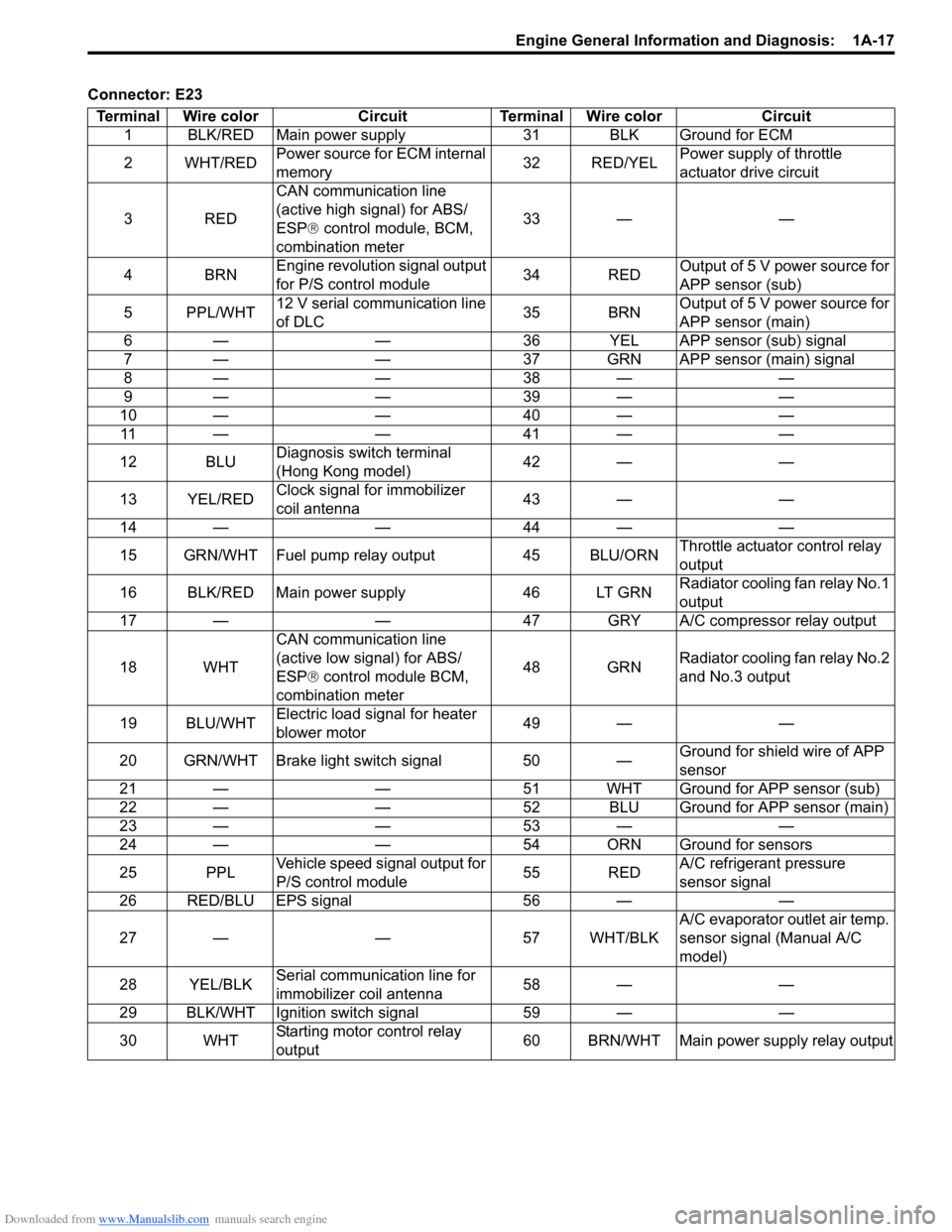
Connector: E23Terminal Wire color Circuit Terminal Wire color Circuit 1 BLK/RED Main power supply 31 BLK Ground for ECM
2WHT/RED Power source for ECM internal
memory 32 RED/YELPower supply of throttle
actuator drive circuit
3RED CAN communication line
(active high signal) for ABS/
ESP®
control module, BCM,
combination meter 33 — —
4BRN Engine revolution signal output
for P/S control module 34 REDOutput of 5 V power source for
APP sensor (sub)
5 PPL/WHT 12 V serial communication line
of DLC 35 BRNOutput of 5 V power source for
APP sensor (main)
6 — — 36 YEL APP sensor (sub) signal
7 — — 37 GRN APP sensor (main) signal
8— — 38— —
9— — 39— —
10——40—— 11——41——
12 BLU Diagnosis switch terminal
(Hong Kong model) 42 — —
13 YEL/RED Clock signal for immobilizer
coil antenna 43 — —
14——44——
15 GRN/WHT Fuel pump relay output 45 BLU/ORN Throttle actuator control relay
output
16 BLK/RED Main power supply 46 LT GRN Radiator cooling fan relay No.1
output
17 — — 47 GRY A/C compressor relay output
18 WHT CAN communication line
(active low signal) for ABS/
ESP®
control module BCM,
combination meter 48 GRN
Radiator cooling fan relay No.2
and No.3 output
19 BLU/WHT Electric load signal for heater
blower motor 49 — —
20 GRN/WHT Brake light switch signal 50 — Ground for shield wire of APP
sensor
21 — — 51 WHT Ground for APP sensor (sub)
22 — — 52 BLU Ground for APP sensor (main)
23——53——
24 — — 54 ORN Ground for sensors
25 PPL Vehicle speed signal output for
P/S control module 55 REDA/C refrigerant pressure
sensor signal
26 RED/BLU EPS signal 56 — —
27 — — 57 WHT/BLK A/C evaporator outlet air temp.
sensor signal (Manual A/C
model)
28 YEL/BLK Serial communication line for
immobilizer coil antenna 58 — —
29 BLK/WHT Ignition switch signal 59 — —
30 WHT Starting motor control relay
output 60 BRN/WHT Main power supply relay output
Page 68 of 1496
Downloaded from www.Manualslib.com manuals search engine 1A-18 Engine General Information and Diagnosis:
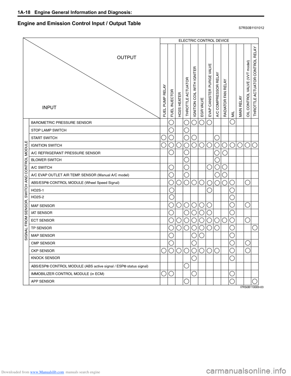
Engine and Emission Control Input / Output TableS7RS0B1101012
INPUTOUTPUT
ELECTRIC CONTROL DEVICE
BAROMETRIC PRESSURE SENSOR
STOP LAMP SWITCH
START SWITCH
IGNITION SWITCH
A/C REFRIGERANT PRESSURE SENSOR
BLOWER SWITCH
A/C SWITCH
A/C EVAP OUTLET AIR TEMP. SENSOR (Manual A/C model)
ABS/ESP
® CONTROL MODULE (Wheel Speed Signal)
HO2S-1
HO2S-2
IAT SENSOR MAF SENSOR
ECT SENSOR
TP SENSOR
MAP SENSOR
CMP SENSOR
CKP SENSOR
KNOCK SENSOR
ABS/ESP
® CONTROL MODULE (ABS active signal / ESP® status signal)
IMMOBILIZER CONTROL MODULE (in ECM)
APP SENSOR
FUEL PUMP RELAY
FUEL INJECTOR
HO2S HEATER THROTTLE ACTUATOR
THROTTLE ACTUATOR CONTROL RELAY
IGNITION COIL WITH IGNITER
EGR VALVE
EVAP CANISTER PURGE VALVEA/C COMPRESSOR RELAY RADIATOR FAN RELAY
MIL
MAIN RELAY
OIL CONTROL VALVE
(VVT model)
SIGNAL FROM SENSOR, SWITCH AND CONTROL MODULE
I7RS0B110009-03
Page 70 of 1496
Downloaded from www.Manualslib.com manuals search engine 1A-20 Engine General Information and Diagnosis:
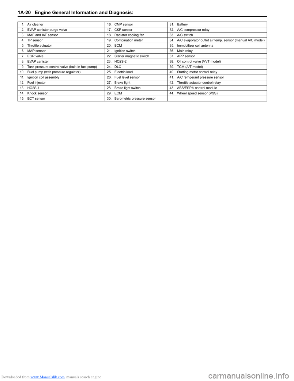
1. Air cleaner16. CMP sensor31. Battery
2. EVAP canister purge valve 17. CKP sensor32. A/C compressor relay
3. MAF and IAT sensor 18. Radiator cooling fan33. A/C switch
4. TP sensor 19. Combination meter34. A/C evaporator outlet air temp. sensor (manual A/C model)
5. Throttle actuator 20. BCM35.Immobilizer coil antenna
6. MAP sensor 21. Ignition switch36. Main relay
7. EGR valve 22. Starter magnetic switch37. APP sensor
8. EVAP canister 23. HO2S-238. Oil control valve (VVT model)
9. Tank pressure control valve (built-in fuel pump) 24. DLC 39. TCM (A/T model)
10. Fuel pump (with pressure regulator) 25. Electric load40. Starting motor control relay
11. Ignition coil assembly 26. Fuel level sensor41. A/C refrigerant pressure sensor
12. Fuel injector 27. Brake light42. Throttle actuator control relay
13. HO2S-1 28. Brake light switch43. ABS/ESP® control module
14. Knock sensor 29. ECM44. Wheel speed sensor (VSS)
15. ECT sensor 30. Barometric pressure sensor
Page 71 of 1496
Downloaded from www.Manualslib.com manuals search engine Engine General Information and Diagnosis: 1A-21
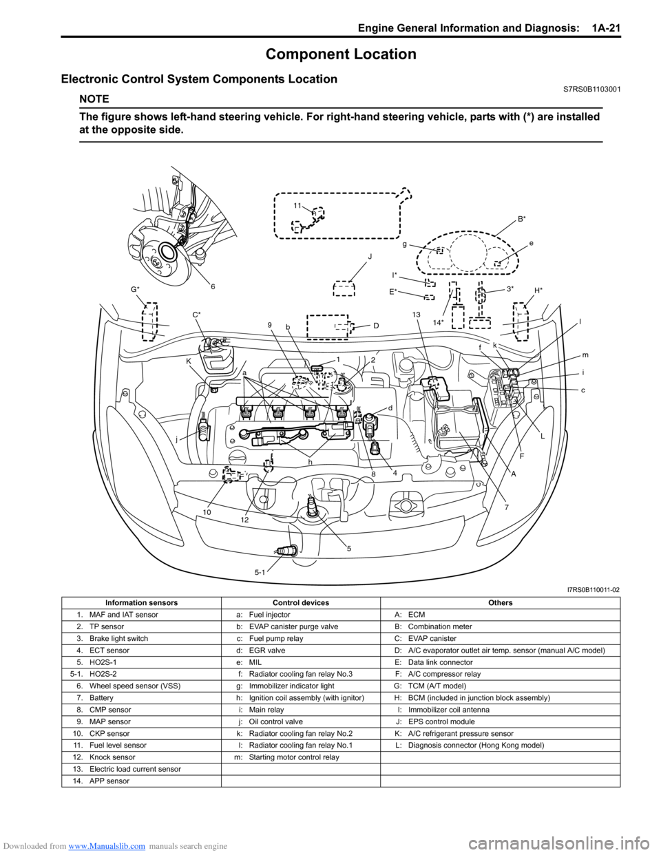
Component Location
Electronic Control System Components LocationS7RS0B1103001
NOTE
The figure shows left-hand steering vehicle. For right-hand steering vehicle, parts with (*) are installed
at the opposite side.
I*
E*
G*
D
K H*
J
C*
7
A
F
c
L
i m
f
B*
e
g
k
l
13
3*
4
j
10 12 h
58
a
9
b
1
5-1
d
2
11
6
14*
I7RS0B110011-02
Information sensors Control devices Others
1. MAF and IAT sensor a: Fuel injectorA: ECM
2. TP sensor b: EVAP canister purge valve B: Combination meter
3. Brake light switch c: Fuel pump relayC: EVAP canister
4. ECT sensor d: EGR valveD: A/C evaporator outlet air temp. sensor (manual A/C model)
5. HO2S-1 e: MILE: Data link connector
5-1. HO2S-2 f: Radiator cooling fan relay No.3F: A/C compressor relay
6. Wheel speed sensor (VSS) g: Immobilizer indicator lightG: TCM (A/T model)
7. Battery h: Ignition coil assembly (with ignitor) H: BCM (included in junction block assembly)
8. CMP sensor i: Main relayI: Immobilizer coil antenna
9. MAP sensor j: Oil control valveJ: EPS control module
10. CKP sensor k: Radiator cooling fan relay No.2K: A/C refrigerant pressure sensor
11. Fuel level sensor l: Radiator cooling fan relay No.1L: Diagnosis connector (Hong Kong model)
12. Knock sensor m: Starting motor control relay
13. Electric load current sensor
14. APP sensor
Page 80 of 1496
Downloaded from www.Manualslib.com manuals search engine 1A-30 Engine General Information and Diagnosis:
�)
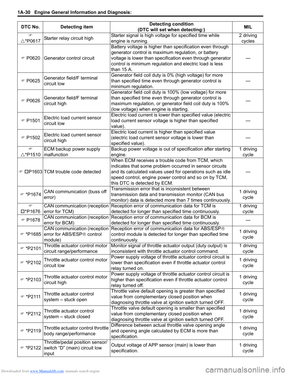
�U *P0617 Starter relay circuit high Starter signal is high voltage for specified time while
engine is running. 2 driving
cycles
�) P0620 Generator control circuit Battery voltage is higher than specification even through
generator control is maximum regulation, or battery
voltage is lower than specification even through generator
control is minimum regulation
and electric load is less
than 15 A. —
�) P0625 Generator field/F terminal
circuit low Generator field coil duty is
0% (high voltage) for more
than specified time even through generator control is
minimum regulation. —
�) P0626 Generator field/F terminal
circuit high Generator field coil duty is
100% (low voltage) for more
than specified time even through generator control is
maximum regulation, or generator field coil duty is 100%
(low voltage) when engine is starting. —
�) P1501 Electric load current sensor
circuit low Electric load current is lowe
r than specified value (electric
load current sensor voltage is higher than specified
value). —
�) P1502 Electric load current sensor
circuit high Electric load current is higher than specified value
(electric load current sens
or voltage is lower than
specified value). —
�)
�U *P1510 ECM backup power supply
malfunction Backup power voltage is out of
specification after starting
engine. 1 driving
cycle
�) �† P1603 TCM trouble code detected When ECM receives a trouble code from TCM, which
indicates that some problem occurred in sensor circuits
and its calculated values used for operations such as idle
speed control, engine power control and so on by TCM,
this DTC is detected by ECM. —
�) *P1674 CAN communication (buss off
error) Transmission error that
is inconsistent between
transmission data and transmission monitor (CAN bus
monitor) data is detected more than 7 times continuously. 1 driving
cycle
�)
�† *P1676 CAN communication (reception
error for TCM) Reception error of communication data for TCM is
detected for longer than specified time continuously. 1 driving
cycle
�) P1678 CAN communication (reception
error for BCM) Reception error of communication data for BCM is
detected for longer than specified time continuously.
—
�) *P1685 CAN communication (reception
error for ABS/ESP
® control
module) Reception error of communication data for ABS/ESP
®
co
ntrol module is detected for longer than specified time
continuously. 1 driving
cycle
�) *P2101 Throttle actuator control motor
circuit range/performance Monitor signal of throttle actuator output (duty output) is
inconsistent with throttle actuator control command. 1 driving
cycle
�) *P2102 Throttle actuator control motor
circuit low Power supply voltage of throttle actuator control circuit is
lower than specification even
if throttle actuator control
relay turned on. 1 driving
cycle
�) *P2103 Throttle actuator control motor
circuit high Power supply voltage of throttle actuator control circuit is
higher than specification even if throttle actuator control
relay turned off. 1 driving
cycle
�) *P2111 Throttle actuator control
system – stuck open Throttle valve default opening is greater than specified
value from complementary closed position when
diagnosing throttle valve at ignition switch turned OFF. 1 driving
cycle
�) *P2112 Throttle actuator control
system – stuck closed Throttle valve default opening is smaller than specified
value from complementary closed position when
diagnosing throttle valve at ignition switch turned OFF. 1 driving
cycle
�) *P2119 Throttle actuator control throttle
body range/performance Difference between actual throttle valve opening angle
and opening angle calculated by ECM is more than
specification. 1 driving
cycle
�) *P2122 Throttle/pedal position sensor/
switch “D” (main) circuit low
input Output voltage of APP sensor (main) is lower than
specification.
1 driving
cycle
DTC No. Detecting item
Detecting condition
(DTC will set when detecting:) MIL
Page 97 of 1496
Downloaded from www.Manualslib.com manuals search engine Engine General Information and Diagnosis: 1A-47
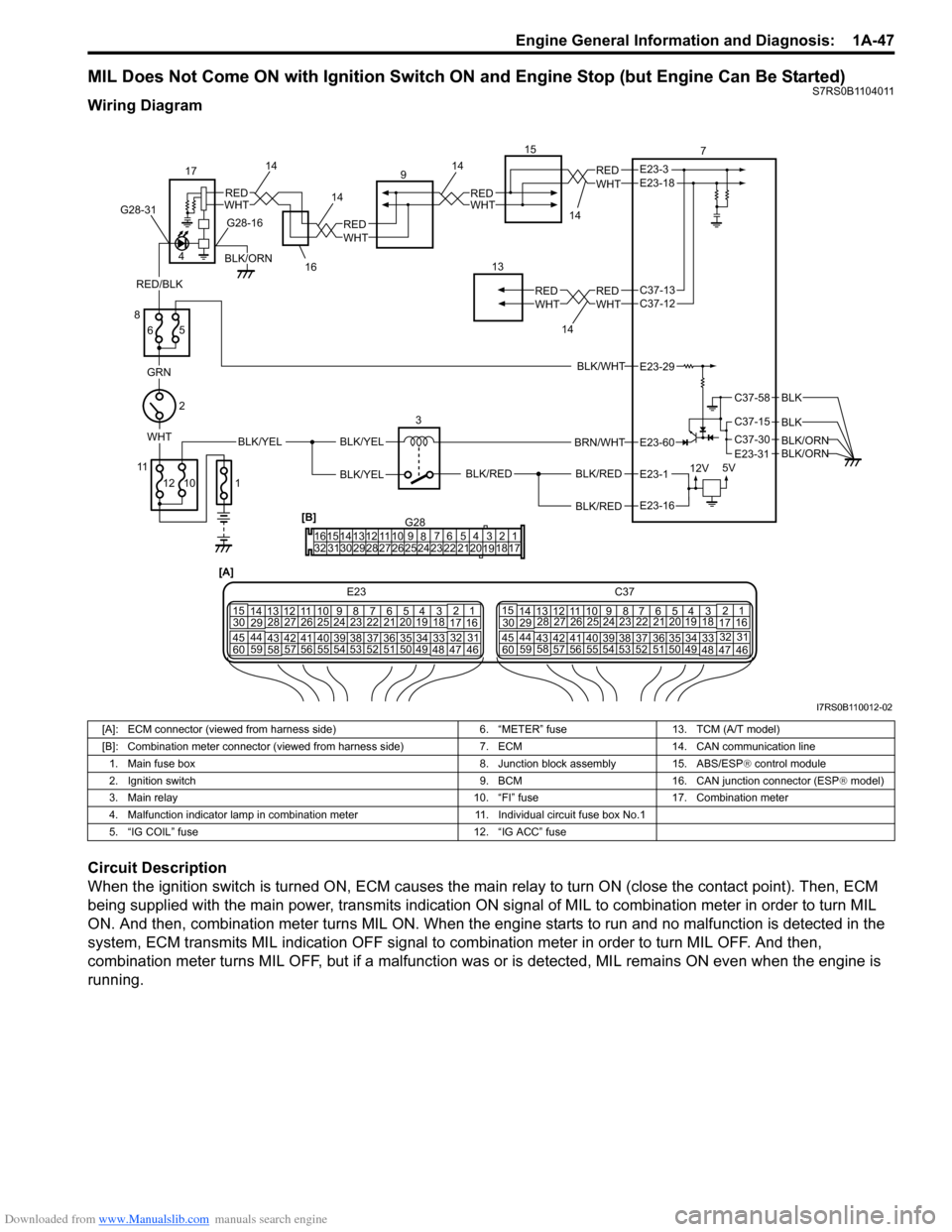
MIL Does Not Come ON with Ignition Switch ON and Engine Stop (but Engine Can Be Started)S7RS0B1104011
Wiring Diagram
Circuit Description
When the ignition switch is turned ON, ECM causes the main relay to turn ON (close the contact point). Then, ECM
being supplied with the main power, transmits indication ON si gnal of MIL to combination meter in order to turn MIL
ON. And then, combination meter turns MIL ON. When the engine starts to run and no malfunction is detected in the
system, ECM transmits MIL indication OFF signal to combination meter in order to turn MIL OFF. And then,
combination meter turns MIL OFF, but if a malfunction was or is detected, MIL remains ON even when the engine is
running.
G281234567
8
910
11
1213141516
1718
19
20
212223242526272829303132
[B]
[A]
E23 C37
34
1819
567
10
11
17
20
47 46
495051
2122
52 16
25 9
24
14
29
5557 54 53
59
60 58 2
262728
15
30
56 4832 31
34353637
4042 39 38
44
45 43 41 331
1213
238
34
1819
567
10
11
17
20
47 46
495051
2122
52 16
25 9
24
14
29
5557 54 53
59
60 58 2
262728
15
30
56 4832 31
34353637
4042 39 38
44
45 43 41 331
12
13
238
BLK/WHT
BLK/RED
BLK/RED
BRN/WHT
BLK/REDWHTBLK/YEL
GRN
12V 5V
2
3
8
6 7
E23-29
E23-3
E23-1
E23-60
E23-18
E23-16
1014
14
12
11
RED/BLK
C37-58
C37-15
C37-30
BLK
E23-31
BLK
BLK/ORNBLK/ORN
4
WHTREDWHTRED
BLK/ORN
G28-16
15
13
14
1414
G28-31
BLK/YEL
BLK/YEL
WHTRED
WHTRED
WHTREDC37-13 C37-12
WHTRED
9
17
5 1 16
I7RS0B110012-02
[A]: ECM connector (viewed from harness side)
6. “METER” fuse13. TCM (A/T model)
[B]: Combination meter connector (viewed from harness side) 7. ECM14. CAN communication line
1. Main fuse box 8. Junction block assembly15. ABS/ESP® control module
2. Ignition switch 9. BCM16. CAN junction connector (ESP® model)
3. Main relay 10. “FI” fuse17. Combination meter
4. Malfunction indicator lamp in combination meter 11. Individual circuit fuse box No.1
5. “IG COIL” fuse 12. “IG ACC” fuse
Page 133 of 1496
Downloaded from www.Manualslib.com manuals search engine Engine General Information and Diagnosis: 1A-83
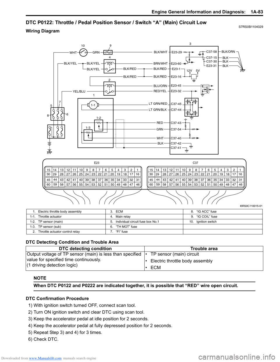
DTC P0122: Throttle / Pedal Position Sensor / Switch “A” (Main) Circuit LowS7RS0B1104029
Wiring Diagram
DTC Detecting Condition and Trouble Area
NOTE
When DTC P0122 and P0222 are indicated together, it is possible that “RED” wire open circuit.
DTC Confirmation Procedure
1) With ignition switch turned OFF, connect scan tool.
2) Turn ON ignition switch and clear DTC using scan tool.
3) Keep the accelerator pedal at idle position for 2 seconds.
4) Keep the accelerator pedal at fully depressed position for 2 seconds.
5) Repeat Step 3) and 4) for 3 times.
6) Check DTC.
E23 C37
34
1819
567
1011
17
20
47 46
495051
2122
52 16
25 9
24
14
29
55
57 54 53
59
60 58 2
262728
15
30
56 4832 31
34353637
40
42 39 38
44
45 43 41 331
1213
238
34
1819
567
1011
17
20
47 46
495051
2122
52 16
25 9
24
14
29
55
57 54 53
59
60 58 2
262728
15
30
56 4832 31
34353637
40
42 39 38
44
45 43 41 331
1213
238
12V
5VBLK/REDBLK/RED
BLK/YEL
12BLK/YEL
BLK/YEL
BRN/WHT
E23-1
E23-60
C37-58
C37-15 C37-30
BLK/ORN
BLKBLKE23-31 BLK
BLK/RED
BLU/ORN
RED/YELYEL/BLU
LT GRN/RED
LT GRN/BLK
RED
GRN
WHT
BLK
E23-16
E23-45
E23-32
C37-45
C37-44
C37-41C37-42
C37-40
C37-54
C37-43
1-1
1-2
1-3 3
4
5
8 67
10
9
E23-29 GRNBLK/WHTWHT
BLK/RED
I6RS0C110015-01
1. Electric throttle body assembly
3. ECM 8. “IG ACC” fuse
1-1. Throttle actuator 4. Main relay 9. “IG COIL” fuse
1-2. TP sensor (main) 5. Individual circuit fuse box No.110. Ignition switch
1-3. TP sensor (sub) 6. “TH MOT” fuse
2. Throttle actuator control relay 7. “FI” fuse
DTC detecting condition Trouble area
Output voltage of TP sensor (main) is less than specified
value for specified time continuously.
(1 driving detection logic) • TP sensor (main) circuit
• Electric throttle body assembly
•ECM