Intake valve clearance SUZUKI SWIFT 2007 2.G Service Workshop Manual
[x] Cancel search | Manufacturer: SUZUKI, Model Year: 2007, Model line: SWIFT, Model: SUZUKI SWIFT 2007 2.GPages: 1496, PDF Size: 34.44 MB
Page 34 of 1496
Downloaded from www.Manualslib.com manuals search engine 0B-4 Maintenance and Lubrication:
Accessory Drive Belt ReplacementS7RS0B0206002
Water Pump and Generator Drive Belt
Replace belt with new one referring to “Water Pump /
Generator Drive Belt Removal and Installation in Section
1J”.
A/C Compressor Drive Belt
Replace belt with new one referring to “Compressor
Drive Belt Removal and Inst allation in Section 7B”.
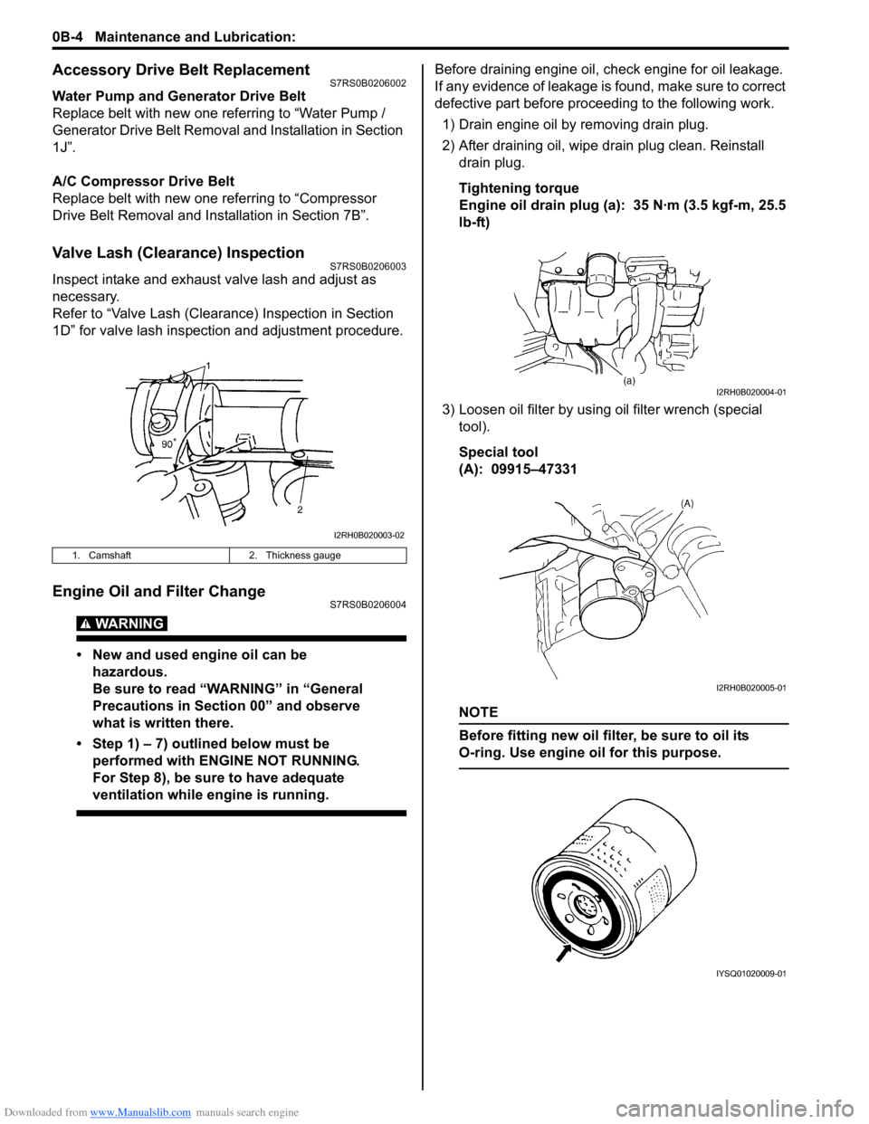
Valve Lash (Clearance) InspectionS7RS0B0206003
Inspect intake and exhaust valve lash and adjust as
necessary.
Refer to “Valve Lash (Clearance) Inspection in Section
1D” for valve lash inspection and adjustment procedure.
Engine Oil and Filter ChangeS7RS0B0206004
WARNING!
• New and used engine oil can be
hazardous.
Be sure to read “WARNING” in “General
Precautions in Section 00” and observe
what is written there.
• Step 1) – 7) outlined below must be performed with ENGINE NOT RUNNING.
For Step 8), be sure to have adequate
ventilation while engine is running.
Before draining engine oil, check engine for oil leakage.
If any evidence of leakage is found, make sure to correct
defective part before proceeding to the following work.
1) Drain engine oil by removing drain plug.
2) After draining oil, wipe drain plug clean. Reinstall drain plug.
Tightening torque
Engine oil drain plug (a): 35 N·m (3.5 kgf-m, 25.5
lb-ft)
3) Loosen oil filter by using oil filter wrench (special
tool).
Special tool
(A): 09915–47331
NOTE
Before fitting new oil filter, be sure to oil its
O-ring. Use engine oil for this purpose.
1. Camshaft 2. Thickness gauge
I2RH0B020003-02
I2RH0B020004-01
I2RH0B020005-01
IYSQ01020009-01
Page 47 of 1496

Downloaded from www.Manualslib.com manuals search engine Table of Contents 1-iii
EVAP Canister Purge Valve and Its Circuit
Inspection.......................................................... 1B-2
Vacuum Passage Inspection .............................. 1B-3
Vacuum Hose and Purge Valve Chamber Inspection.......................................................... 1B-3
EVAP Canister Purge Valve Inspection .............. 1B-3
EVAP Canister Inspection ... ................................ 1B-4
EGR Valve Removal and Installation .................. 1B-4
EGR Valve Inspection ......................................... 1B-4
PCV Hose Inspection .......................................... 1B-4
PCV Valve Inspection ......................................... 1B-5
Special Tools and Equipmen t ............................. 1B-5
Special Tool ........................................................ 1B-5
Engine Electrical Devices .. ..................... 1C-1
Repair Instructions .............................................. 1C-1
ECM Removal and Installation ............................ 1C-1
MAP Sensor Inspection ...................................... 1C-2
Electric Throttle Body Assembly On-Vehicle
Inspection.......................................................... 1C-2
Electric Throttle Body System Calibration ........... 1C-5
APP Sensor Assembly On-V ehicle Inspection .... 1C-5
APP Sensor Assembly Removal and Installation ......................................................... 1C-5
APP Sensor Assembly Inspection ...................... 1C-6
ECT Sensor Removal and In stallation ................ 1C-6
ECT Sensor Inspection ....................................... 1C-7
HO2S-1 and HO2S-2 Heater On-Vehicle Inspection.......................................................... 1C-7
HO2S-1 and HO2S-2 Removal and Installation ......................................................... 1C-7
CMP Sensor Removal and In stallation ............... 1C-8
Camshaft Position (CMP) Se nsor Inspection ...... 1C-8
CKP Sensor Removal and Installation ................ 1C-9
CKP Sensor Inspection ....................................... 1C-9
Knock Sensor Removal and Installation ........... 1C-10
Main Relay, Fuel Pump Relay and Starting
Motor Control Relay Inspection....................... 1C-10
MAF and IAT Sensor On-Vehicle Inspection .... 1C-11
MAF and IAT Sensor Removal and Installation ....................................................... 1C-11
MAF and IAT Sensor Inspection ....................... 1C-12
Electric Load Current Sensor On-Vehicle Inspection........................................................ 1C-12
Specifications ..................................................... 1C-13
Tightening Torque Specifications ...................... 1C-13
Engine Mechanical ......... ......................... 1D-1
General Description ............................................. 1D-1
Engine Construction Description ......................... 1D-1
Camshaft Position Control (VVT Variable Valve Timing) System Description .................... 1D-2
Diagnostic Information and Procedures ............ 1D-4 Compression Check ............................................ 1D-4
Engine Vacuum Check ....................................... 1D-5
Valve Lash (Clearance) Inspection ..................... 1D-6
Repair Instructions .............................................. 1D-9 Air Cleaner Components ..................................... 1D-9
Air Cleaner Element Removal and Installation .... 1D-9 Air Cleaner Element Ins
pection and Cleaning ..1D-10
Cylinder Head Co ver Removal and
Installation .......................................................1D-10
Throttle Body and Intake Manifold
Components ....................................................1D-12
Throttle Body On-Vehicle Inspection.................1D-13
Electric Throttle Body Assembly Removal and Installation .......................................................1D-13
Throttle Body Cleaning......................................1D-14
Intake Manifold Removal and Installation .........1D-14
Engine Mountings Components ........................1D-16
Engine Assembly Removal and Installation ......1D-17
Timing Chain Cover Components .....................1D-20
Timing Chain Cover Removal and Installation ..1D-21
Timing Chain Cover Inspection .........................1D-23
Oil Control Valve Removal and Installation .......1D-23
Oil Control Valve Inspection ..............................1D-24
Timing Chain and Chain Tensioner Components ....................................................1D-24
Timing Chain and Chain Tensioner Removal and Installation ................................................1D-25
Timing Chain and Chain Tensioner Inspection ..1D-27
Camshaft, Tappet and Shim Components ........1D-28
Camshaft, Tappet and Shim Removal and Installation .......................................................1D-29
Camshaft, Tappet and Shim Inspection ............1D-31
Valves and Cylinder Head Components ...........1D-34
Valves and Cylinder Head Removal and
Installation .......................................................1D-35
Valves and Cylinder Head Disassembly and Assembly.........................................................1D-37
Valves and Valve Guides Inspection.................1D-40
Cylinder Head Inspection . .................................1D-42
Valve Spring Inspection ....................................1D-43
Pistons, Piston Rings , Connecting Rods and
Cylinders Components ....................................1D-44
Pistons, Piston Rings , Connecting Rods and
Cylinders Removal and Installation .................1D-45
Pistons, Piston Rings , Connecting Rods and
Cylinders Disassembly and Assembly ............1D-46
Cylinders, Pistons and Piston Rings Inspection ........................................................1D-47
Piston Pins and Connecting Rods Inspection ...1D-49
Crank Pin and Connecting Rod Bearings Inspection ........................................................1D-50
Main Bearings, Cran kshaft and Cylinder
Block Components ..........................................1D-53
Main Bearings, Cran kshaft and Cylinder
Block Removal and Installa tion .......................1D-54
Crankshaft Inspection .......................................1D-57
Main Bearings Inspection . .................................1D-59
Sensor Plate Inspection ....................................1D-63
Rear Oil Seal Inspection ...................................1D-63
Flywheel Inspection...........................................1D-63
Cylinder Block Inspection ..................................1D-63
Specifications .................... .................................1D-64
Tightening Torque Specifications ......................1D-64
Special Tools and Equipmen t ...........................1D-66
Recommended Service Material .......................1D-66
Special Tool ......................................................1D-66
Page 91 of 1496
Downloaded from www.Manualslib.com manuals search engine Engine General Information and Diagnosis: 1A-41
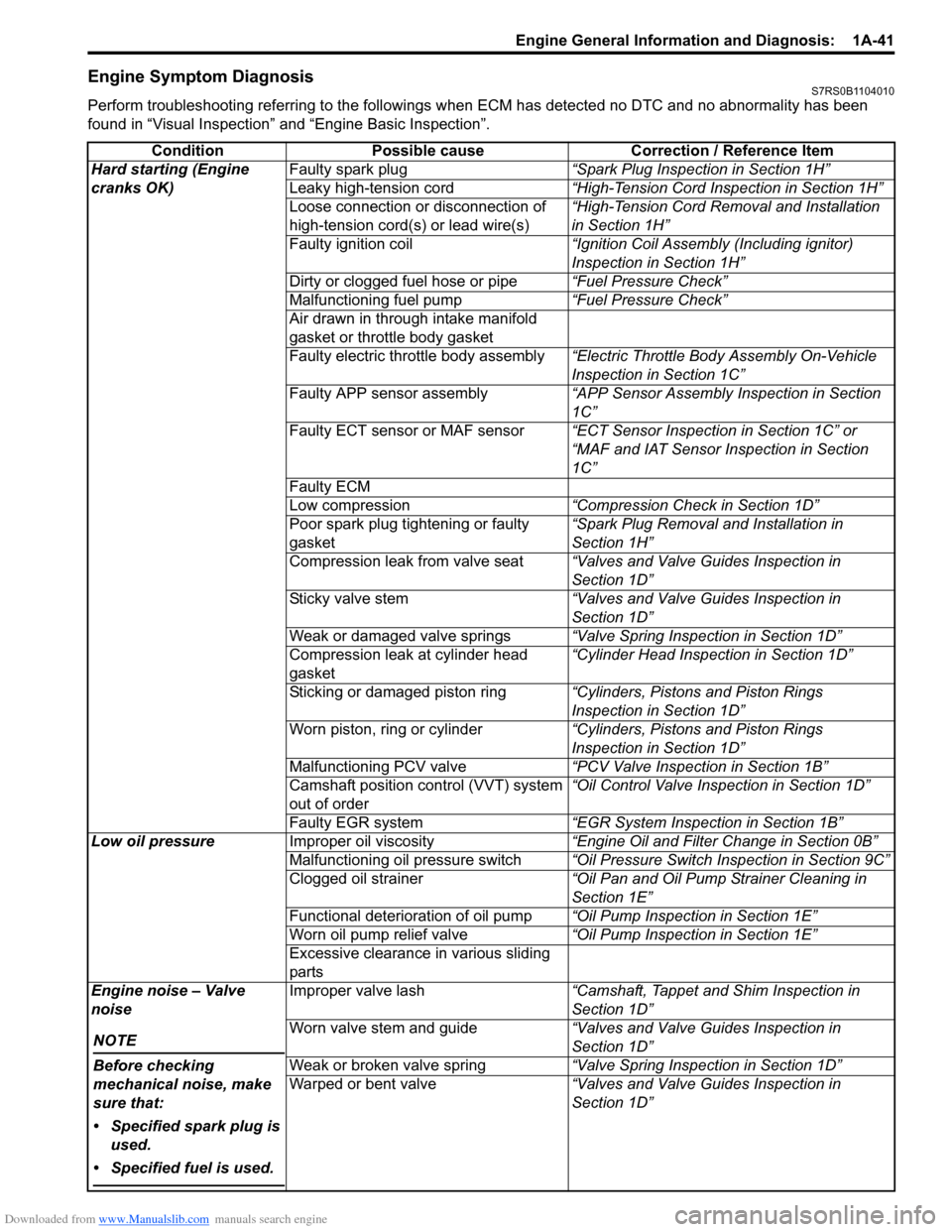
Engine Symptom DiagnosisS7RS0B1104010
Perform troubleshooting referring to the followings when ECM has detected no DTC and no abnormality has been
found in “Visual Inspection” and “Engine Basic Inspection”.
Condition Possible cause Correction / Reference Item
Hard starting (Engine
cranks OK) Faulty spark plug
“Spark Plug Inspection in Section 1H”
Leaky high-tension cord “High-Tension Cord Inspection in Section 1H”
Loose connection or disconnection of
high-tension cord(s) or lead wire(s) “High-Tension Cord Removal and Installation
in Section 1H”
Faulty ignition coil “Ignition Coil Assembly (Including ignitor)
Inspection in Section 1H”
Dirty or clogged fuel hose or pipe “Fuel Pressure Check”
Malfunctioning fuel pump “Fuel Pressure Check”
Air drawn in through intake manifold
gasket or throttle body gasket
Faulty electric throttle body assembly “Electric Throttle Body Assembly On-Vehicle
Inspection in Section 1C”
Faulty APP sensor assembly “APP Sensor Assembly Inspection in Section
1C”
Faulty ECT sensor or MAF sensor “ECT Sensor Inspection in Section 1C” or
“MAF and IAT Sensor Inspection in Section
1C”
Faulty ECM
Low compression “Compression Check in Section 1D”
Poor spark plug tightening or faulty
gasket “Spark Plug Removal and Installation in
Section 1H”
Compression leak from valve seat “Valves and Valve Guides Inspection in
Section 1D”
Sticky valve stem “Valves and Valve Guides Inspection in
Section 1D”
Weak or damaged valve springs “Valve Spring Inspection in Section 1D”
Compression leak at cylinder head
gasket “Cylinder Head Inspection in Section 1D”
Sticking or damaged piston ring “Cylinders, Pistons and Piston Rings
Inspection in Section 1D”
Worn piston, ring or cylinder “Cylinders, Pistons and Piston Rings
Inspection in Section 1D”
Malfunctioning PCV valve “PCV Valve Inspection in Section 1B”
Camshaft position control (VVT) system
out of order “Oil Control Valve Inspection in Section 1D”
Faulty EGR system “EGR System Inspection in Section 1B”
Low oil pressure Improper oil viscosity “Engine Oil and Filter Change in Section 0B”
Malfunctioning oil pressure switch “Oil Pressure Switch Inspection in Section 9C”
Clogged oil strainer “Oil Pan and Oil Pump Strainer Cleaning in
Section 1E”
Functional deterioration of oil pump “Oil Pump Inspection in Section 1E”
Worn oil pump relief valve “Oil Pump Inspection in Section 1E”
Excessive clearance in various sliding
parts
Engine noise – Valve
noise
NOTE
Before checking
mechanical noise, make
sure that:
• Specified spark plug is used.
• Specified fuel is used.
Improper valve lash “Camshaft, Tappet and Shim Inspection in
Section 1D”
Worn valve stem and guide “Valves and Valve Guides Inspection in
Section 1D”
Weak or broken valve spring “Valve Spring Inspection in Section 1D”
Warped or bent valve “Valves and Valve Guides Inspection in
Section 1D”
Page 102 of 1496
Downloaded from www.Manualslib.com manuals search engine 1A-52 Engine General Information and Diagnosis:
DTC P0011 / P0012: “A” Camshaft Position - Timing Over-Advanced or System Performance / -
Retarded
S7RS0B1104014
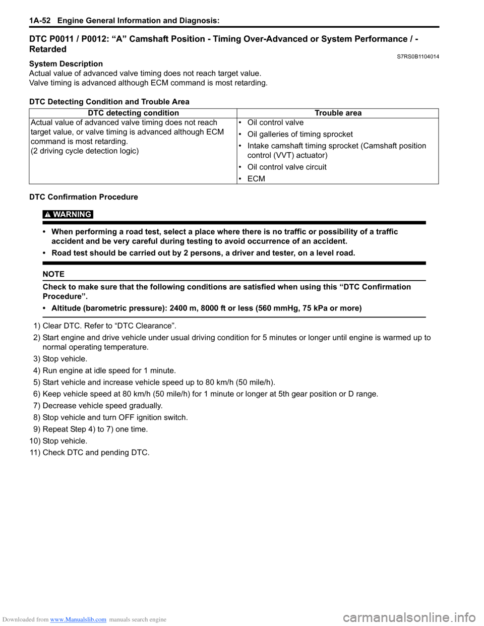
System Description
Actual value of advanced valve timing does not reach target value.
Valve timing is advanced although ECM command is most retarding.
DTC Detecting Condition and Trouble Area
DTC Confirmation Procedure
WARNING!
• When performing a road test, select a place where there is no traffic or possibility of a traffic accident and be very careful during testing to avoid occurrence of an accident.
• Road test should be carried out by 2 persons, a driver and tester, on a level road.
NOTE
Check to make sure that the following conditions are satisfied when using this “DTC Confirmation
Procedure”.
• Altitude (barometric pressure): 2400 m, 8000 ft or less (560 mmHg, 75 kPa or more)
1) Clear DTC. Refer to “DTC Clearance”.
2) Start engine and drive vehicle under usual driving condition for 5 minutes or longer until engine is warmed up to normal operating temperature.
3) Stop vehicle.
4) Run engine at idle speed for 1 minute.
5) Start vehicle and increase vehicle speed up to 80 km/h (50 mile/h).
6) Keep vehicle speed at 80 km/h (50 mile/h) for 1 minute or longer at 5th gear position or D range.
7) Decrease vehicle speed gradually.
8) Stop vehicle and turn OFF ignition switch.
9) Repeat Step 4) to 7) one time.
10) Stop vehicle. 11) Check DTC and pending DTC. DTC detecting condition
Trouble area
Actual value of advanced valve timing does not reach
target value, or valve timi ng is advanced although ECM
command is most retarding.
(2 driving cycle detection logic) • Oil control valve
• Oil galleries of timing sprocket
• Intake camshaft timing sprocket (Camshaft position
control (VVT) actuator)
• Oil control valve circuit
•ECM
Page 291 of 1496
Downloaded from www.Manualslib.com manuals search engine Engine Mechanical: 1D-6
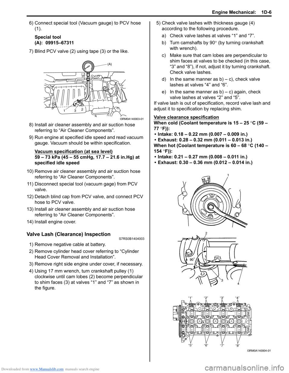
6) Connect special tool (Vacuum gauge) to PCV hose (1).
Special tool
(A): 09915–67311
7) Blind PCV valve (2) using tape (3) or the like.
8) Install air cleaner assembly and air suction hose referring to “Air Cleaner Components”.
9) Run engine at specified idle speed and read vacuum gauge. Vacuum should be within specification.
Vacuum specification (at sea level)
59 – 73 kPa (45 – 55 cmHg, 17.7 – 21.6 in.Hg) at
specified idle speed
10) Remove air cleaner assembly and air suction hose referring to “Air Cleaner Components”.
11) Disconnect special tool (vacuum gage) from PCV valve.
12) Detach blind cap from PCV valve, and connect PCV hose to PCV valve.
13) Install air cleaner assembly and air suction hose referring to “Air Cleaner Components”.
14) Install engine cover.
Valve Lash (Clearance) InspectionS7RS0B1404003
1) Remove negative cable at battery.
2) Remove cylinder head cover referring to “Cylinder Head Cover Removal and Installation”.
3) Remove right side engine under cover, if necessary.
4) Using 17 mm wrench, turn crankshaft pulley (1) clockwise until cam lobes (2) become perpendicular
to shim faces (3) at valves “1” and “7” as shown in
the figure. 5) Check valve lashes with thickness gauge (4)
according to the following procedure.
a) Check valve lashes at valves “1” and “7”.
b) Turn camshafts by 90 ° (by turning crankshaft
with wrench).
c) Make sure that cam lobes are perpendicular to shim faces at valves to be checked (in this case,
“3” and “8”), if not, adjust it by turning crankshaft.
Check valve lashes.
d) In the same manner as b) – c), check valve
lashes at valves “4” and “6”.
e) In the same manner as b) – c) again, check valve lashes at valves “2” and “5”.
If valve lash is out of specification, record valve lash and
adjust it to specification by replacing shim.
Valve clearance specification
When cold (Coolant te mperature is 15 – 25 °C (59 –
77 °F)):
• Intake: 0.18 – 0.22 mm (0.007 – 0.009 in.)
• Exhaust: 0.28 – 0.32 mm (0.011 – 0.013 in.)
When hot (Coolant temperature is 60 – 68 °C (140 –
154 °F)):
• Intake: 0.21 – 0.27 mm (0.008 – 0.011 in.)
• Exhaust: 0.30 – 0.36 mm (0.012 – 0.014 in.)
(A)
13 2
I3RM0A140003-01
I3RM0A140004-01
Page 292 of 1496
Downloaded from www.Manualslib.com manuals search engine 1D-7 Engine Mechanical:
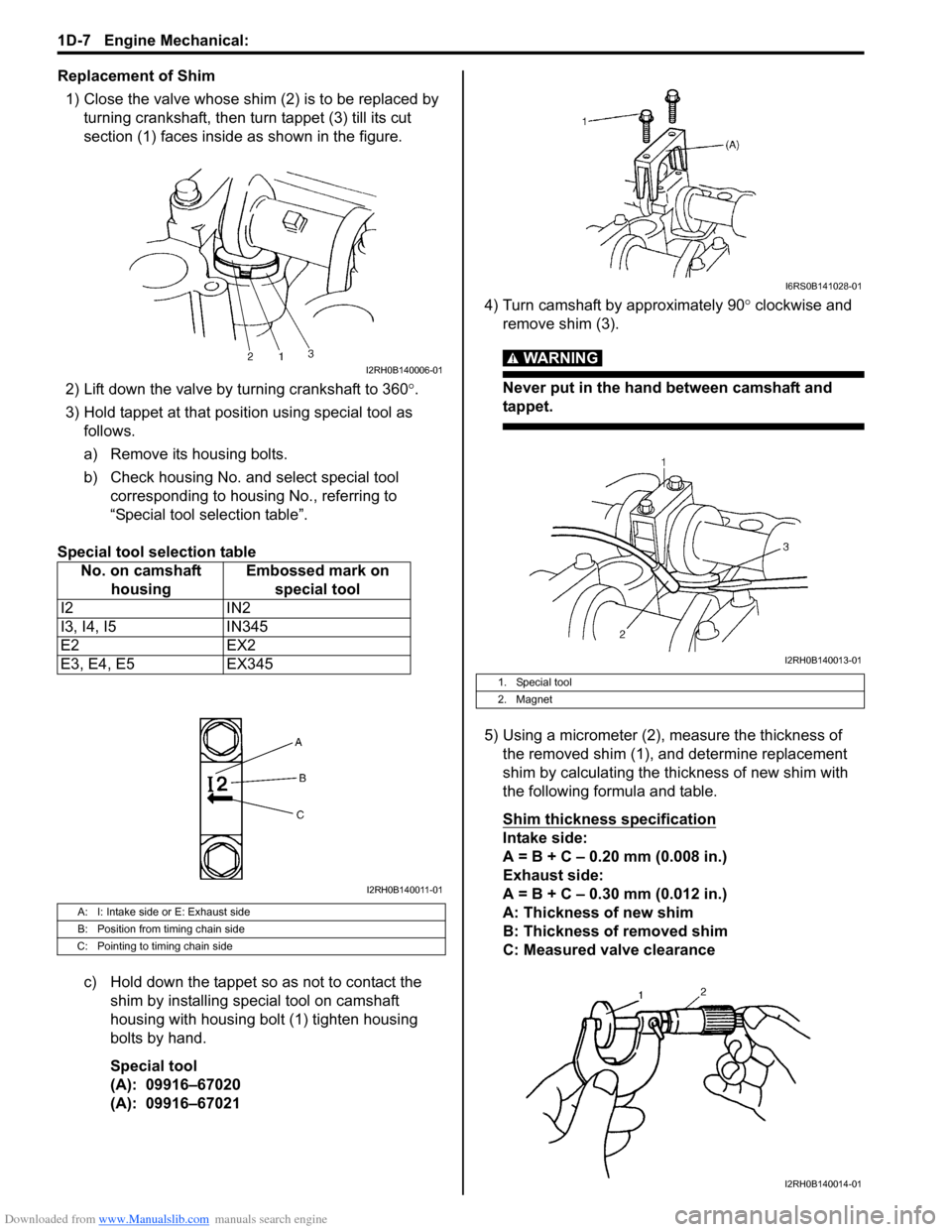
Replacement of Shim1) Close the valve whose shim (2) is to be replaced by turning crankshaft, then tu rn tappet (3) till its cut
section (1) faces inside as shown in the figure.
2) Lift down the valve by turning crankshaft to 360° .
3) Hold tappet at that position using special tool as follows.
a) Remove its housing bolts.
b) Check housing No. and select special tool corresponding to housing No., referring to
“Special tool selection table”.
Special tool selection table
c) Hold down the tappet so as not to contact the shim by installing special tool on camshaft
housing with housing bolt (1) tighten housing
bolts by hand.
Special tool
(A): 09916–67020
(A): 09916–67021 4) Turn camshaft by approximately 90
° clockwise and
remove shim (3).
WARNING!
Never put in the hand between camshaft and
tappet.
5) Using a micrometer (2), measure the thickness of the removed shim (1), and determine replacement
shim by calculating the thickness of new shim with
the following formula and table.
Shim thickness specification
Intake side:
A = B + C – 0.20 mm (0.008 in.)
Exhaust side:
A = B + C – 0.30 mm (0.012 in.)
A: Thickness of new shim
B: Thickness of removed shim
C: Measured valve clearance
No. on camshaft
housing Embossed mark on
special tool
I2 IN2
I3, I4, I5 IN345
E2 EX2
E3, E4, E5 EX345
A: I: Intake side or E: Exhaust side
B: Position from timing chain side
C: Pointing to timing chain side
I2RH0B140006-01
I2RH0B140011-01
1. Special tool
2. Magnet
I6RS0B141028-01
I2RH0B140013-01
I2RH0B140014-01
Page 293 of 1496
Downloaded from www.Manualslib.com manuals search engine Engine Mechanical: 1D-8
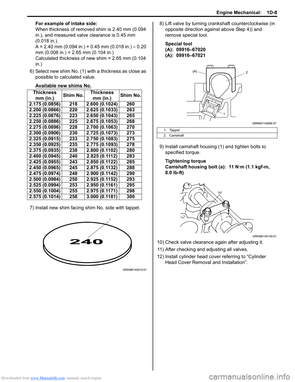
For example of intake side:
When thickness of removed shim is 2.40 mm (0.094
in.), and measured valve clearance is 0.45 mm
(0.018 in.).
A = 2.40 mm (0.094 in.) + 0.45 mm (0.018 in.) – 0.20
mm (0.008 in.) = 2.65 mm (0.104 in.)
Calculated thickness of new shim = 2.65 mm (0.104
in.)
6) Select new shim No. (1) with a thickness as close as possible to calculated value.
Available new shims No.
7) Install new shim facing shim No. side with tappet. 8) Lift valve by turning crankshaft counterclockwise (in
opposite direction against above Step 4)) and
remove special tool.
Special tool
(A): 09916–67020
(A): 09916–67021
9) Install camshaft housing (1) and tighten bolts to specified torque.
Tightening torque
Camshaft housing bolt (a ): 11 N·m (1.1 kgf-m,
8.0 lb-ft)
10) Check valve clearance again after adjusting it. 11) After checking and adjusting all valves.
12) Install cylinder head cover referring to “Cylinder Head Cover Removal and Installation”.
Thickness
mm (in.) Shim No.Thickness
mm (in.) Shim No.
2.175 (0.0856) 218 2.600 (0.1024) 260
2.200 (0.0866) 220 2.625 (0.1033) 263
2.225 (0.0876) 223 2.650 (0.1043) 265
2.250 (0.0886) 225 2.675 (0.1053) 268
2.275 (0.0896) 228 2.700 (0.1063) 270
2.300 (0.0906) 230 2.725 (0.1073) 273
2.325 (0.0915) 233 2.750 (0.1083) 275
2.350 (0.0925) 235 2.775 (0.1093) 278
2.375 (0.0935) 238 2.800 (0.1102) 280
2.400 (0.0945) 240 2.825 (0.1112) 283
2.425 (0.0955) 243 2.850 (0.1122) 285
2.450 (0.0965) 245 2.875 (0.1132) 288
2.475 (0.0974) 248 2.900 (0.1142) 290
2.500 (0.0984) 250 2.925 (0.1152) 293
2.525 (0.0994) 253 2.950 (0.1161) 295
2.550 (0.1004) 255 2.975 (0.1171) 298
2.575 (0.1014) 258 3.000 (0.1181) 300
I2RH0B140015-01
1. Tappet
2. Camshaft
(A)2
1
I3RM0A140006-01
I2RH0B140149-01
Page 316 of 1496
Downloaded from www.Manualslib.com manuals search engine 1D-31 Engine Mechanical:
7) Install camshaft housing.
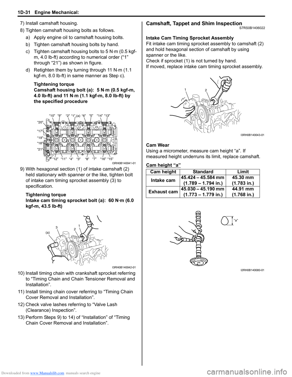
8) Tighten camshaft housing bolts as follows.a) Apply engine oil to camshaft housing bolts.
b) Tighten camshaft housing bolts by hand.
c) Tighten camshaft housing bolts to 5 N ⋅m (0.5 kgf-
m, 4.0 lb-ft) according to numerical order (“1”
through “21”) as shown in figure.
d) Retighten them by turning through 11 N⋅ m (1.1
kgf-m, 8.0 lb-ft) in same manner as Step c).
Tightening torque
Camshaft housing bolt (a): 5 N ⋅m (0.5 kgf-m,
4.0 lb-ft) and 11 N ⋅m (1.1 kgf-m, 8.0 lb-ft) by
the specified procedure
9) With hexagonal section (1) of intake camshaft (2) held stationary with spanner or the like, tighten bolt
of intake cam timing sp rocket assembly (3) to
specification.
Tightening torque
Intake cam timing sprocket bolt (a): 60 N·m (6.0
kgf-m, 43.5 lb-ft)
10) Install timing chain with cr ankshaft sprocket referring
to “Timing Chain and Chain Tensioner Removal and
Installation”.
11) Install timing chain cover referring to “Timing Chain Cover Removal and Installation”.
12) Check valve lashes referring to “Valve Lash (Clearance) Inspection”.
13) Perform Steps 9) to 14) of “Installation” of “Timing Chain Cover Removal and Installation”.Camshaft, Tappet and Shim InspectionS7RS0B1406022
Intake Cam Timing Sprocket Assembly
Fit intake cam timing sprocket assembly to camshaft (2)
and hold hexagonal section of camshaft by using
spanner or the like.
Check if sprocket (1) is not turned by hand.
If moved, replace intake ca m timing sprocket assembly.
Cam Wear
Using a micrometer, measure cam height “a”. If
measured height underruns its limit, replace camshaft.
Cam height “a”
“10”“9” “2” “1”,(a) “6” “5” “14” “13”
“20”
“17” “19”
“18”
“21”
“12”“11”
“4” “3” “8” “7” “16” “15”
I3RH0B140041-01
1
2
3
(a)
I3RH0B140042-01
Cam height Standard Limit
Intake cam 45.424 – 45.584 mm
(1.789 – 1.794 in.) 45.30 mm
(1.783 in.)
Exhaust cam 45.030 – 45.190 mm
(1.773 – 1.779 in.) 44.91 mm
(1.768 in.)
2
1
I3RH0B140043-01
I2RH0B140080-01
Page 349 of 1496
Downloaded from www.Manualslib.com manuals search engine Engine Mechanical: 1D-64
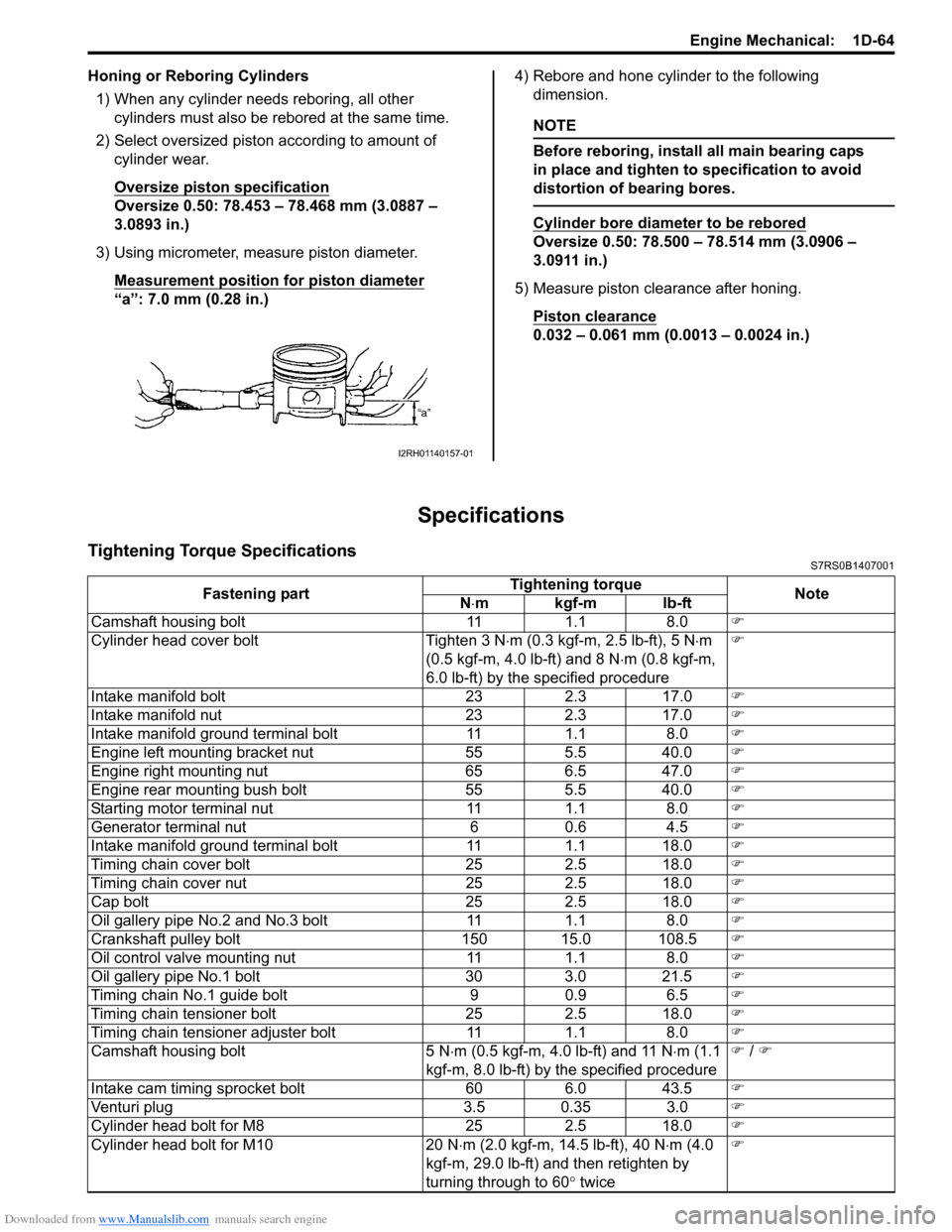
Honing or Reboring Cylinders1) When any cylinder needs reboring, all other cylinders must also be rebored at the same time.
2) Select oversized piston according to amount of cylinder wear.
Oversize piston specification
Oversize 0.50: 78.453 – 78.468 mm (3.0887 –
3.0893 in.)
3) Using micrometer, measure piston diameter. Measurement position for piston diameter
“a”: 7.0 mm (0.28 in.) 4) Rebore and hone cylinder to the following
dimension.
NOTE
Before reboring, install all main bearing caps
in place and tighten to specification to avoid
distortion of bearing bores.
Cylinder bore diameter to be rebored
Oversize 0.50: 78.500 – 78.514 mm (3.0906 –
3.0911 in.)
5) Measure piston clearance after honing. Piston clearance
0.032 – 0.061 mm (0.0013 – 0.0024 in.)
Specifications
Tightening Torque SpecificationsS7RS0B1407001
I2RH01140157-01
Fastening part Tightening torque
Note
N ⋅mkgf-mlb-ft
Camshaft housing bolt 11 1.1 8.0 �)
Cylinder head cover bolt Tighten 3 N ⋅m (0.3 kgf-m, 2.5 lb-ft), 5 N ⋅m
(0.5 kgf-m, 4.0 lb-ft) and 8 N ⋅m (0.8 kgf-m,
6.0 lb-ft) by the specified procedure �)
Intake manifold bolt 23 2.3 17.0 �)
Intake manifold nut 23 2.3 17.0 �)
Intake manifold ground terminal bolt 11 1.1 8.0 �)
Engine left mounting bracket nut 55 5.5 40.0 �)
Engine right mounting nut 65 6.5 47.0 �)
Engine rear mounting bush bolt 55 5.5 40.0 �)
Starting motor terminal nut 11 1.1 8.0 �)
Generator terminal nut 6 0.6 4.5 �)
Intake manifold ground terminal bolt 11 1.1 18.0 �)
Timing chain cover bolt 25 2.5 18.0 �)
Timing chain cover nut 25 2.5 18.0 �)
Cap bolt 25 2.5 18.0 �)
Oil gallery pipe No.2 and No.3 bolt 11 1.1 8.0 �)
Crankshaft pulley bolt 150 15.0 108.5 �)
Oil control valve mounting nut 11 1.1 8.0 �)
Oil gallery pipe No.1 bolt 30 3.0 21.5 �)
Timing chain No.1 guide bolt 9 0.9 6.5 �)
Timing chain tensioner bolt 25 2.5 18.0 �)
Timing chain tensioner adjuster bolt 11 1.1 8.0 �)
Camshaft housing bolt 5 N ⋅m (0.5 kgf-m, 4.0 lb-ft) and 11 N ⋅m (1.1
kgf-m, 8.0 lb-ft) by the specified procedure �)
/ �)
Intake cam timing sprocket bolt 60 6.0 43.5 �)
Venturi plug 3.5 0.35 3.0 �)
Cylinder head bolt for M8 25 2.5 18.0 �)
Cylinder head bolt for M10 20 N ⋅m (2.0 kgf-m, 14.5 lb-ft), 40 N ⋅m (4.0
kgf-m, 29.0 lb-ft) and then retighten by
turning through to 60 ° twice �)
Page 934 of 1496

Downloaded from www.Manualslib.com manuals search engine 7-ii Table of Contents
Recommended Service Material ....................... 7B-33
Special Tool ...................................................... 7B-33
Automatic Type .................... .................................7B-34
Precautions.........................................................7B-34 A/C System Caution .......................................... 7B-34
Precautions in Diagnosing Trouble ................... 7B-34
Precautions on Servicing A/C System .............. 7B-34
General Description .......... .................................7B-34
Auto A/C System Descript ion ............................ 7B-34
HVAC Control Module Operation Description ... 7B-36
Refrigerant Type Identifica tion .......................... 7B-36
Sub-Cool A/C System Description .................... 7B-36
A/C Operation Description ................................ 7B-36
On-Board Diagnostic System Description ......... 7B-37
Schematic and Routing Diagram ......................7B-37 Major Components of A/C System .................... 7B-37
A/C System Wiring Diagra m ............................. 7B-38
Diagnostic Information and Procedures ..........7B-39 A/C System Symptom Diagnosis ...................... 7B-39
Abnormal Noise Sympto m Diagnosis of A/C
System ............................................................ 7B-42
DTC Check........................................................ 7B-42
DTC Clearance ................................................. 7B-43
DTC Table ......................................................... 7B-44
Fail-Safe Table ................. ................................. 7B-45
Scan Tool Data ................................................. 7B-46
Air Conditioning System Check......................... 7B-47
Visual Inspection ............................................... 7B-49
DTC B1502: Inside Air Temperature Sensor and/or Its Circuit Malfunction .......................... 7B-49
DTC B1503: A/C Evaporator Air Temperature Sensor and/or Its Circuit Malfunction .............. 7B-50
DTC B1504: Sunload Sensor and/or Its Circuit Malfunction ......... ................................. 7B-52
DTC B1511: Temperature Control Actuator (Position Sensor) and/or Its Circuit
Malfunction ...................................................... 7B-53
DTC B1512: Air flow Control Actuator (Position Sensor) and/or Its Circuit
Malfunction ...................................................... 7B-55
DTC B1513: Temperature Control Actuator and/or Its Circuit Malfunction .......................... 7B-57
DTC B1514: Air Flow Co ntrol Actuator and/or
Its Circuit Malfunction ...................................... 7B-60
DTC B1541: HVAC Control Module Back-Up Power Supply Malfunction .............................. 7B-62
DTC B1546: A/C Refrigerant Pressure Malfunction ...................................................... 7B-63
DTC B1551: Serial Communication Circuit Malfunction ...................................................... 7B-63
DTC B1552: Serial Communication Signal Malfunction ...................................................... 7B-64
DTC B1553: CAN Communication Signal Malfunction ...................................................... 7B-65
DTC B1557: Vehicle Speed Sensor Signal Malfunction ...................................................... 7B-65
DTC B1561: Engine Coolant Temperature Sensor Signal Malfunctio n .............................. 7B-66 DTC B1562: Outside Air Temperature Sensor
Signal Malfunction ........................................... 7B-66
DTC B1563: A/C Refr igerant Pressure
Sensor Signal Malfunction .............................. 7B-66
Inspection of HVAC Control Module and Its Circuit .............................................................. 7B-67
A/C System Performance Inspection ................ 7B-70
A/C System Inspection at ECM ......................... 7B-70
Repair Instructions ............ ................................7B-71
Operation Procedure for Refrigerant Charge .... 7B-71
HVAC Unit Components ................................... 7B-72
HVAC Unit Removal and In stallation ................ 7B-73
Temperature Control Actuator Removal and Installation ....................................................... 7B-73
Temperature Control Actuat or Inspection ......... 7B-73
Air Flow Control Actuator Removal and Installation ....................................................... 7B-74
Air Flow Control Actuator Inspection ................. 7B-74
Air Intake Control Actuator Removal and Installation ....................................................... 7B-75
Air Intake Control Actuator Inspection............... 7B-75
Actuator Linkage Inspection .............................. 7B-76
Blower Motor Controller Removal and Installation ....................................................... 7B-76
Blower Motor Controller Inspection ................... 7B-76
HVAC Control Module Removal and Installation ....................................................... 7B-77
Sunload Sensor Removal and Installation ........ 7B-77
Sunload Sensor Inspection ............................... 7B-77
Outside Air Temperature Sensor Removal and Installation ................................................ 7B-77
Outside Air Temperature Sensor Inspection ..... 7B-77
Inside Air Temperature Sensor Removal and Installation ....................................................... 7B-78
Inside Air Temperature Sens or Inspection ........ 7B-78
Condenser Assembly On-Vehicle Inspection .... 7B-78
Condenser Assembly Removal and Installation ....................................................... 7B-78
Receiver/Dryer Removal and Installation .......... 7B-78
Evaporator Inspection ....................................... 7B-78
Evaporator Temperature Sensor Removal and Installation ................................................ 7B-78
Evaporator Temperature Se nsor Inspection ..... 7B-78
Expansion Valve Removal an d Installation ....... 7B-78
Expansion Valve Inspection .............................. 7B-78
A/C Refrigerant Pressure Sensor and Its Circuit Inspection............................................. 7B-78
A/C Refrigerant Pressu re Sensor Removal
and Installation ................................................ 7B-78
Compressor Relay Inspection .
.......................... 7B-78
Compressor Drive Belt Inspection and Adjustment ...................................................... 7B-78
Compressor Drive Belt Removal and Installation ....................................................... 7B-79
Compressor Assembly Removal and Installation ....................................................... 7B-79
Compressor Assembly Components................. 7B-79
Magnet Clutch Removal and Installation........... 7B-79
Magnet Clutch Inspection.................................. 7B-79
Relief Valve Inspection...................................... 7B-79