Pin Ecu SUZUKI SWIFT 2007 2.G Service Workshop Manual
[x] Cancel search | Manufacturer: SUZUKI, Model Year: 2007, Model line: SWIFT, Model: SUZUKI SWIFT 2007 2.GPages: 1496, PDF Size: 34.44 MB
Page 42 of 1496
Downloaded from www.Manualslib.com manuals search engine 0B-12 Maintenance and Lubrication:
HVAC Air Filter (If Equipped) InspectionS7RS0B0206032
1) Remove HVAC air filter from HVAC unit referring to
“HVAC Air Filter Removal and Installation (If
Equipped) in Section 7A”.
2) Check for dirt and dust. If HVAC air filter is excessively dirty, replace HVAC air filter with new
one. If not, go to next step.
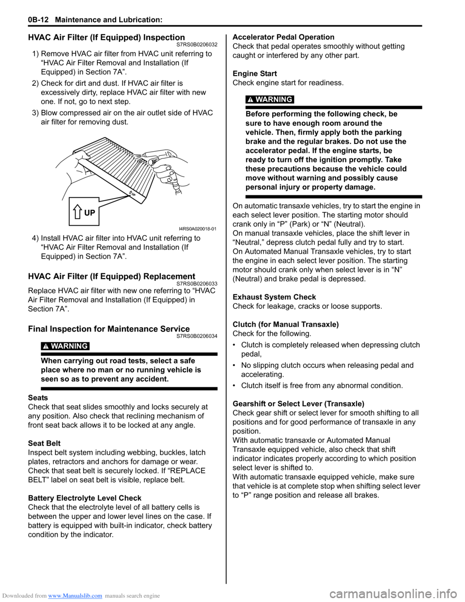
3) Blow compressed air on the air outlet side of HVAC air filter for removing dust.
4) Install HVAC air filter in to HVAC unit referring to
“HVAC Air Filter Removal and Installation (If
Equipped) in Section 7A”.
HVAC Air Filter (If Equipped) ReplacementS7RS0B0206033
Replace HVAC air filter with new one referring to “HVAC
Air Filter Removal and Installation (If Equipped) in
Section 7A”.
Final Inspection for Maintenance ServiceS7RS0B0206034
WARNING!
When carrying out road tests, select a safe
place where no man or no running vehicle is
seen so as to prevent any accident.
Seats
Check that seat slides smoot hly and locks securely at
any position. Also check that reclining mechanism of
front seat back allows it to be locked at any angle.
Seat Belt
Inspect belt system including webbing, buckles, latch
plates, retractors and anchors for damage or wear.
Check that seat belt is securely locked. If “REPLACE
BELT” label on seat belt is visible, replace belt.
Battery Electrolyte Level Check
Check that the electrolyte le vel of all battery cells is
between the upper and lower level lines on the case. If
battery is equipped with built-in indicator, check battery
condition by the indicator. Accelerator Pedal Operation
Check that pedal operates
smoothly without getting
caught or interfered by any other part.
Engine Start
Check engine start for readiness.
WARNING!
Before performing th e following check, be
sure to have enough room around the
vehicle. Then, firmly apply both the parking
brake and the regular brakes. Do not use the
accelerator pedal. If the engine starts, be
ready to turn off the ignition promptly. Take
these precautions because the vehicle could
move without warning and possibly cause
personal injury or property damage.
On automatic transaxle vehicles, try to start the engine in
each select lever position. The starting motor should
crank only in “P” (Park) or “N” (Neutral).
On manual transaxle vehicles, place the shift lever in
“Neutral,” depress clutch pedal fully and try to start.
On Automated Manual Transaxl e vehicles, try to start
the engine in each select le ver position. The starting
motor should crank only when select lever is in “N”
(Neutral) and brake pedal is depressed.
Exhaust System Check
Check for leakage, cracks or loose supports.
Clutch (for Manual Transaxle)
Check for the following.
• Clutch is completely released when depressing clutch pedal,
• No slipping clutch occurs when releasing pedal and accelerating.
• Clutch itself is free fr om any abnormal condition.
Gearshift or Select Lever (Transaxle)
Check gear shift or select lever for smooth shifting to all
positions and for good performance of transaxle in any
position.
With automatic transaxle or Automated Manual
Transaxle equipped vehicle, also check that shift
indicator indicates properly according to which position
select lever is shifted to.
With automatic transaxle equipped vehicle, make sure
that vehicle is at complete stop when shifting select lever
to “P” range position and release all brakes.
I4RS0A020018-01
Page 243 of 1496
Downloaded from www.Manualslib.com manuals search engine Engine General Information and Diagnosis: 1A-193
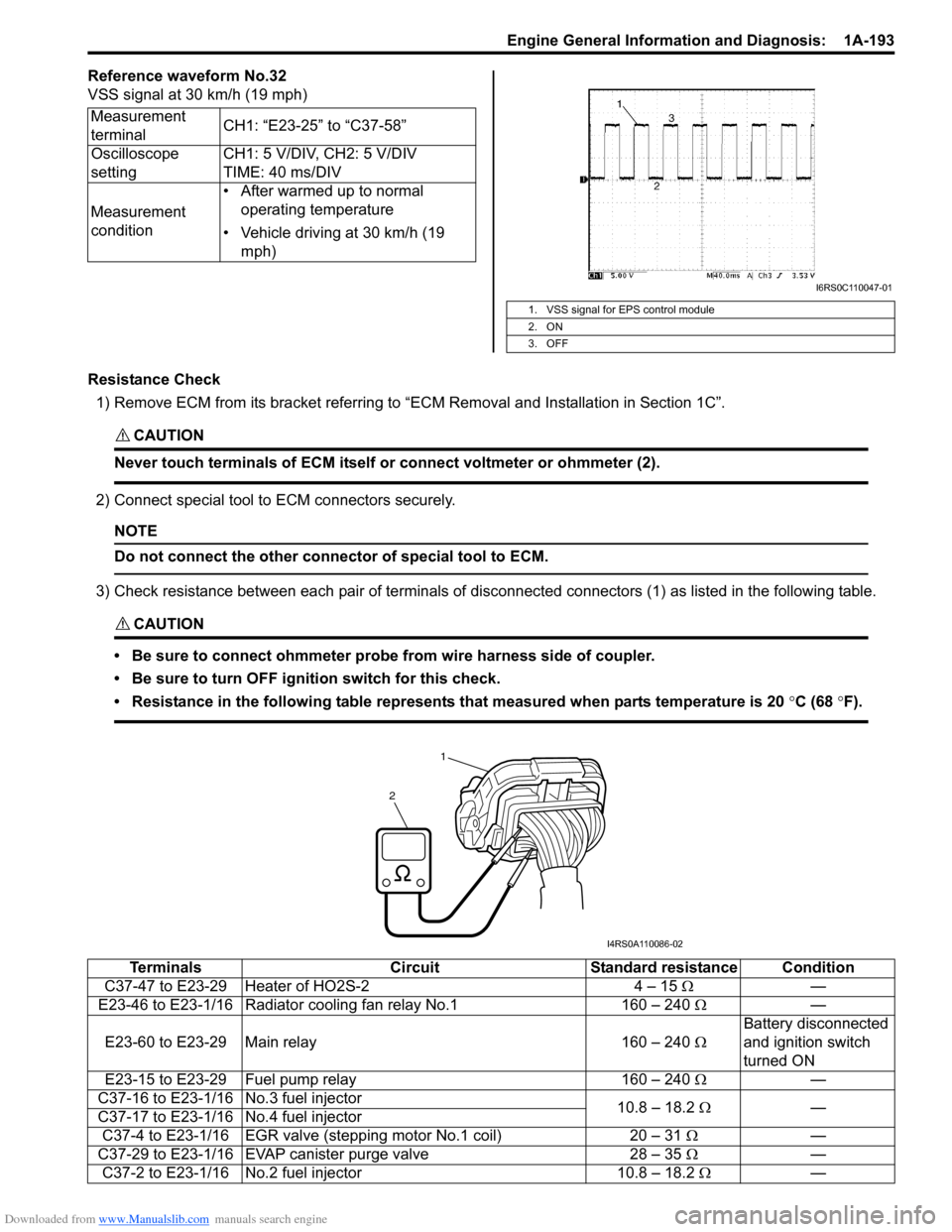
Reference waveform No.32
VSS signal at 30 km/h (19 mph)
Resistance Check1) Remove ECM from its bracket referring to “ECM Removal and Installation in Section 1C”.
CAUTION!
Never touch terminals of ECM itself or connect voltmeter or ohmmeter (2).
2) Connect special tool to ECM connectors securely.
NOTE
Do not connect the other connector of special tool to ECM.
3) Check resistance between each pair of terminals of disconnected connectors (1) as listed in the following table.
CAUTION!
• Be sure to connect ohmmeter probe from wire harness side of coupler.
• Be sure to turn OFF ignition switch for this check.
• Resistance in the following table represents that measured when parts temperature is 20 °C (68 °F).
Measurement
terminal CH1: “E23-25” to “C37-58”
Oscilloscope
setting CH1: 5 V/DIV, CH2: 5 V/DIV
TIME: 40 ms/DIV
Measurement
condition • After warmed up to normal
operating temperature
• Vehicle driving at 30 km/h (19 mph)
1. VSS signal for EPS control module
2. ON
3. OFF
I6RS0C110047-01
1
2
I4RS0A110086-02
Terminals CircuitStandard resistance Condition
C37-47 to E23-29 Heater of HO2S-2 4 – 15 Ω—
E23-46 to E23-1/16 Radiator cooling fan relay No.1 160 – 240 Ω —
E23-60 to E23-29 Main relay 160 – 240 ΩBattery disconnected
and ignition switch
turned ON
E23-15 to E23-29 Fuel pump relay 160 – 240 Ω —
C37-16 to E23-1/16 No.3 fuel injector 10.8 – 18.2 Ω —
C37-17 to E23-1/16 No.4 fuel injector
C37-4 to E23-1/16 EGR valve (st epping motor No.1 coil) 20 – 31 Ω —
C37-29 to E23-1/16 EVAP canister purge valve 28 – 35 Ω —
C37-2 to E23-1/16 No.2 fuel injector 10.8 – 18.2 Ω—
Page 274 of 1496
Downloaded from www.Manualslib.com manuals search engine 1C-2 Engine Electrical Devices:
MAP Sensor InspectionS7RS0B1306002
1) Remove air cleaner assembly.
2) Disconnect connector from MAP sensor.
3) Remove MAP sensor.
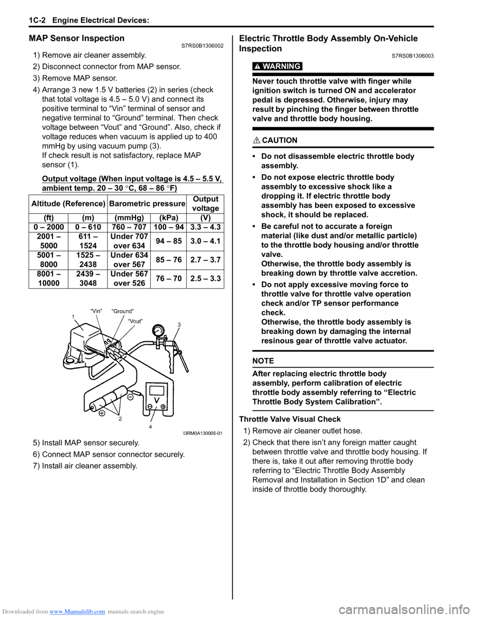
4) Arrange 3 new 1.5 V batteries (2) in series (check that total voltage is 4.5 – 5.0 V) and connect its
positive terminal to “Vin ” terminal of sensor and
negative terminal to “Ground” terminal. Then check
voltage between “Vout” and “Ground”. Also, check if
voltage reduces when vacuum is applied up to 400
mmHg by using vacuum pump (3).
If check result is not satisfactory, replace MAP
sensor (1).
Output voltage (When input voltage is 4.5 – 5.5 V,
ambient temp. 20 – 30 °C, 68 – 86 °F)
5) Install MAP sensor securely.
6) Connect MAP sensor connector securely.
7) Install air cleaner assembly.
Electric Throttle Body Assembly On-Vehicle
Inspection
S7RS0B1306003
WARNING!
Never touch throttle valve with finger while
ignition switch is turned ON and accelerator
pedal is depressed. Otherwise, injury may
result by pinching the finger between throttle
valve and throttle body housing.
CAUTION!
• Do not disassemble electric throttle body assembly.
• Do not expose electric throttle body assembly to excessive shock like a
dropping it. If electric throttle body
assembly has been exposed to excessive
shock, it should be replaced.
• Be careful not to accurate a foreign material (like dust and/ or metallic particle)
to the throttle body housing and/or throttle
valve.
Otherwise, the throttle body assembly is
breaking down by throttle valve accretion.
• Do not apply excessive moving force to throttle valve for thro ttle valve operation
check and/or TP sensor performance
check.
Otherwise, the throttle body assembly is
breaking down by damaging the internal
resinous gear of throttle valve actuator.
NOTE
After replacing electric throttle body
assembly, perform calibration of electric
throttle body assembly referring to “Electric
Throttle Body System Calibration”.
Throttle Valve Visual Check
1) Remove air cleaner outlet hose.
2) Check that there isn’t any foreign matter caught between throttle valve and throttle body housing. If
there is, take it out after removing throttle body
referring to “Electric Th rottle Body Assembly
Removal and Installation in Section 1D” and clean
inside of throttle body thoroughly.
Altitude (Reference) Barometric pressure
Output
voltage
(ft) (m) (mmHg) (kPa) (V)
0 – 2000 0 – 610 760 – 707 100 – 94 3.3 – 4.3 2001 – 5000 611 –
1524 Under 707
over 634 94 – 85 3.0 – 4.1
5001 – 8000 1525 –
2438 Under 634
over 567 85 – 76 2.7 – 3.7
8001 – 10000 2439 –
3048 Under 567
over 526 76 – 70 2.5 – 3.3
I3RM0A130005-01
Page 277 of 1496
Downloaded from www.Manualslib.com manuals search engine Engine Electrical Devices: 1C-5
Electric Throttle Body System CalibrationS7RS0B1306004
NOTE
If working the service described under the
“Precautions of Electric Throttle Body
System Calibration in Section 1A” perform
following steps for electric throttle body
system calibration.
1) If electric throttle body assembly and/or APP sensor
assembly are replaced, perform following steps.
a) Disconnect negative cable at battery for 20 seconds or more for the purpose of clearing
calibration data of closed throttle position from
memory in ECM.
b) Connect negative cable to battery.
2) Keep ignition switch at ON position for 5 seconds or more without running engine.
APP Sensor Assembly On-Vehicle InspectionS7RS0B1306005
1) Check that APP sensor a ssembly has been mounted
to vehicle body properly (no pinched floor carpet,
etc.).
If mounting is not pro perly, reinstall APP sensor
assembly properly refe rring to “APP Sensor
Assembly Removal and Installation”.
2) Connect scan tool to DLC with ignition switch turned OFF.
3) Turn ON ignition switch and select “Data List” mode on scan tool.
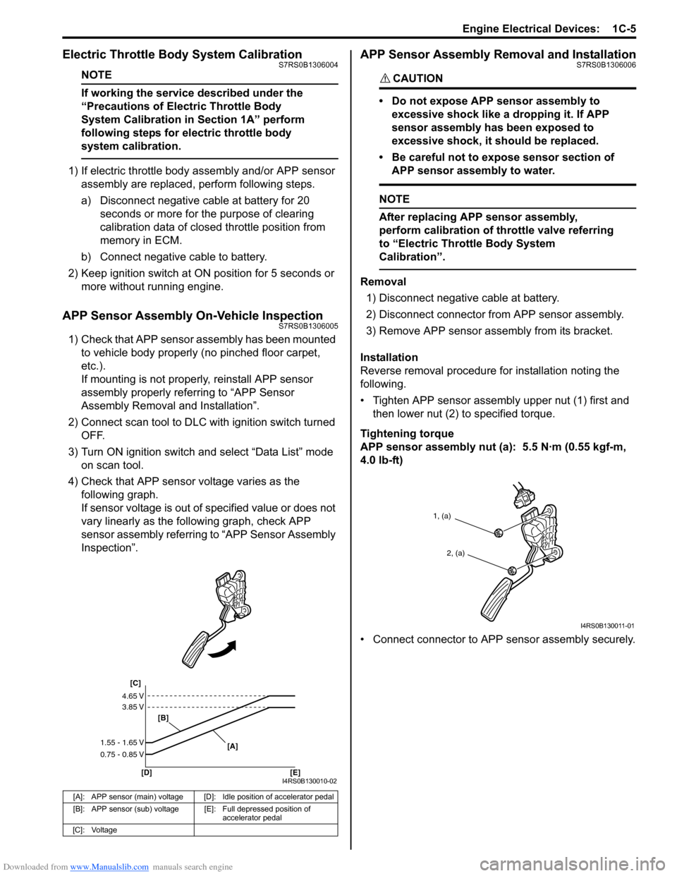
4) Check that APP sensor voltage varies as the following graph.
If sensor voltage is out of specified value or does not
vary linearly as the fo llowing graph, check APP
sensor assembly referring to “APP Sensor Assembly
Inspection”.
APP Sensor Assembly Removal and InstallationS7RS0B1306006
CAUTION!
• Do not expose APP sensor assembly to
excessive shock like a dropping it. If APP
sensor assembly has been exposed to
excessive shock, it should be replaced.
• Be careful not to expose sensor section of APP sensor assembly to water.
NOTE
After replacing APP sensor assembly,
perform calibration of th rottle valve referring
to “Electric Throttle Body System
Calibration”.
Removal
1) Disconnect negative cable at battery.
2) Disconnect connector from APP sensor assembly.
3) Remove APP sensor asse mbly from its bracket.
Installation
Reverse removal procedure for installation noting the
following.
• Tighten APP sensor assembly upper nut (1) first and then lower nut (2) to specified torque.
Tightening torque
APP sensor assembly nut (a): 5.5 N·m (0.55 kgf-m,
4.0 lb-ft)
• Connect connector to APP sensor assembly securely.
[A]: APP sensor (main) voltage [D]: Idle position of accelerator pedal
[B]: APP sensor (sub) voltage [E]: Full depressed position of
accelerator pedal
[C]: Voltage
[C]
[B]
[D] [E] [A]
4.65 V
3.85 V
1.55 - 1.65 V
0.75 - 0.85 V
I4RS0B130010-02
1, (a)
2, (a)
I4RS0B130011-01
Page 280 of 1496
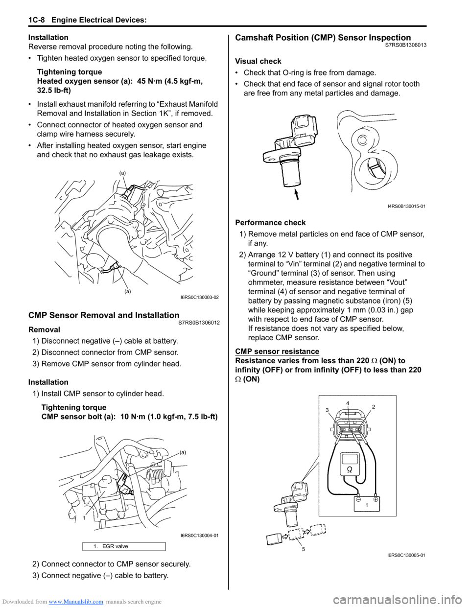
Downloaded from www.Manualslib.com manuals search engine 1C-8 Engine Electrical Devices:
Installation
Reverse removal procedure noting the following.
• Tighten heated oxygen sensor to specified torque.Tightening torque
Heated oxygen sensor (a): 45 N·m (4.5 kgf-m,
32.5 lb-ft)
• Install exhaust manifold referring to “Exhaust Manifold Removal and Installation in Section 1K”, if removed.
• Connect connector of heated oxygen sensor and clamp wire harness securely.
• After installing heated oxygen sensor, start engine and check that no exhaust gas leakage exists.
CMP Sensor Removal and InstallationS7RS0B1306012
Removal
1) Disconnect negative (–) cable at battery.
2) Disconnect connector from CMP sensor.
3) Remove CMP sensor from cylinder head.
Installation 1) Install CMP sensor to cylinder head.
Tightening torque
CMP sensor bolt (a): 10 N·m (1.0 kgf-m, 7.5 lb-ft)
2) Connect connector to CMP sensor securely.
3) Connect negative (–) cable to battery.
Camshaft Position (CMP) Sensor InspectionS7RS0B1306013
Visual check
• Check that O-ring is free from damage.
• Check that end face of sensor and signal rotor tooth are free from any metal particles and damage.
Performance check 1) Remove metal particles on end face of CMP sensor, if any.
2) Arrange 12 V battery (1) and connect its positive terminal to “Vin” terminal (2) and negative terminal to
“Ground” terminal (3) of sensor. Then using
ohmmeter, measure resistance between “Vout”
terminal (4) of sensor and negative terminal of
battery by passing magnetic substance (iron) (5)
while keeping approximately 1 mm (0.03 in.) gap
with respect to end face of CMP sensor.
If resistance does not vary as specified below,
replace CMP sensor.
CMP sensor resistance
Resistance varies from less than 220 Ω (ON) to
infinity (OFF) or from infinity (OFF) to less than 220
Ω (ON)
1. EGR valve
(a)
(a)
I6RS0C130003-02
I6RS0C130004-01
I4RS0B130015-01
I6RS0C130005-01
Page 281 of 1496
Downloaded from www.Manualslib.com manuals search engine Engine Electrical Devices: 1C-9
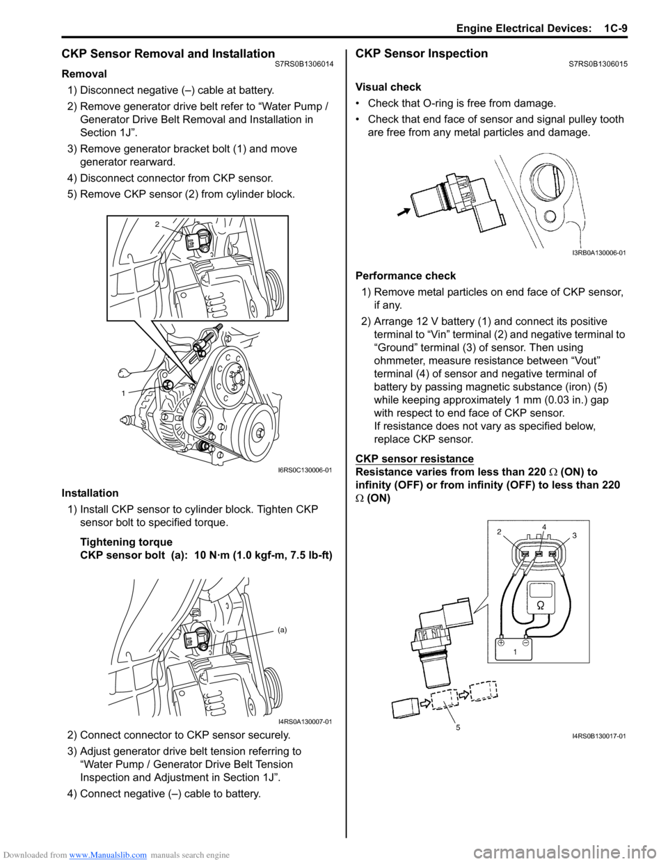
CKP Sensor Removal and InstallationS7RS0B1306014
Removal1) Disconnect negative (–) cable at battery.
2) Remove generator drive belt refer to “Water Pump / Generator Drive Belt Remo val and Installation in
Section 1J”.
3) Remove generator bracket bolt (1) and move generator rearward.
4) Disconnect connector from CKP sensor.
5) Remove CKP sensor (2) from cylinder block.
Installation 1) Install CKP sensor to cylinder block. Tighten CKP sensor bolt to specified torque.
Tightening torque
CKP sensor bolt (a): 10 N·m (1.0 kgf-m, 7.5 lb-ft)
2) Connect connector to CKP sensor securely.
3) Adjust generator drive belt tension referring to “Water Pump / Generator Drive Belt Tension
Inspection and Adjustment in Section 1J”.
4) Connect negative (–) cable to battery.
CKP Sensor InspectionS7RS0B1306015
Visual check
• Check that O-ring is free from damage.
• Check that end face of sensor and signal pulley tooth are free from any metal particles and damage.
Performance check 1) Remove metal particles on end face of CKP sensor, if any.
2) Arrange 12 V battery (1) and connect its positive terminal to “Vin” terminal (2) and negative terminal to
“Ground” terminal (3) of sensor. Then using
ohmmeter, measure resistance between “Vout”
terminal (4) of sensor and negative terminal of
battery by passing magnetic substance (iron) (5)
while keeping approximately 1 mm (0.03 in.) gap
with respect to end face of CKP sensor.
If resistance does not vary as specified below,
replace CKP sensor.
CKP sensor resistance
Resistance varies from less than 220 Ω (ON) to
infinity (OFF) or from infinity (OFF) to less than 220
Ω (ON)
2
1
I6RS0C130006-01
(a)
I4RS0A130007-01
I3RB0A130006-01
I4RS0B130017-01
Page 307 of 1496
Downloaded from www.Manualslib.com manuals search engine Engine Mechanical: 1D-22
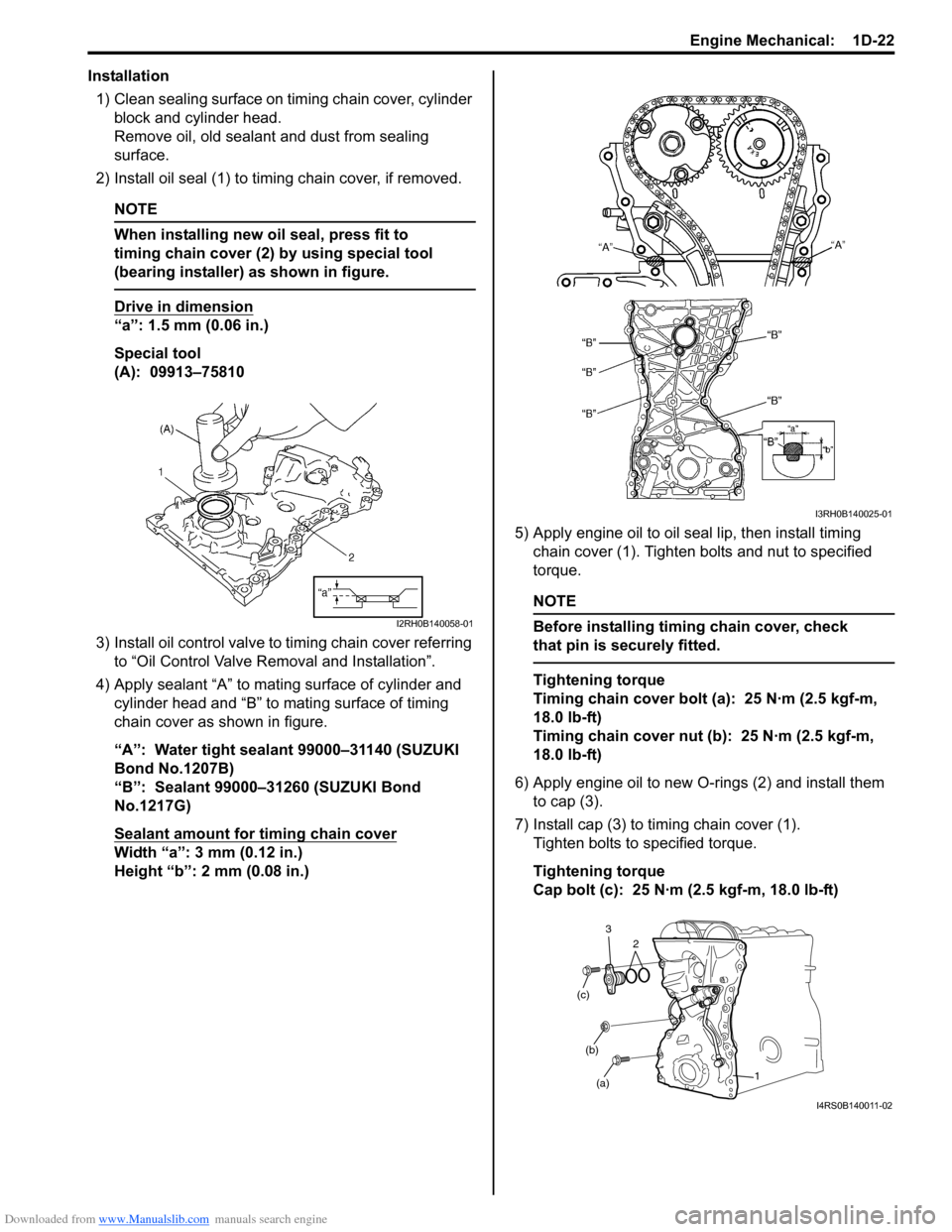
Installation1) Clean sealing surface on timing chain cover, cylinder block and cylinder head.
Remove oil, old sealant and dust from sealing
surface.
2) Install oil seal (1) to timi ng chain cover, if removed.
NOTE
When installing new oil seal, press fit to
timing chain cover (2) by using special tool
(bearing installer) as shown in figure.
Drive in dimension
“a”: 1.5 mm (0.06 in.)
Special tool
(A): 09913–75810
3) Install oil control valve to timing chain cover referring to “Oil Control Valve Removal and Installation”.
4) Apply sealant “A” to mating surface of cylinder and cylinder head and “B” to mating surface of timing
chain cover as shown in figure.
“A”: Water tight sealant 99000–31140 (SUZUKI
Bond No.1207B)
“B”: Sealant 99000–31260 (SUZUKI Bond
No.1217G)
Sealant amount for timing chain cover
Width “a”: 3 mm (0.12 in.)
Height “b”: 2 mm (0.08 in.) 5) Apply engine oil to oil seal lip, then install timing
chain cover (1). Tighten bolts and nut to specified
torque.
NOTE
Before installing timing chain cover, check
that pin is securely fitted.
Tightening torque
Timing chain cover bolt (a): 25 N·m (2.5 kgf-m,
18.0 lb-ft)
Timing chain cover nut (b): 25 N·m (2.5 kgf-m,
18.0 lb-ft)
6) Apply engine oil to new O-rings (2) and install them to cap (3).
7) Install cap (3) to ti ming chain cover (1).
Tighten bolts to specified torque.
Tightening torque
Cap bolt (c): 25 N·m (2.5 kgf-m, 18.0 lb-ft)
I2RH0B140058-01
I3RH0B140025-01
(a)
(b)
(c)
1
2
3
I4RS0B140011-02
Page 319 of 1496
Downloaded from www.Manualslib.com manuals search engine Engine Mechanical: 1D-34
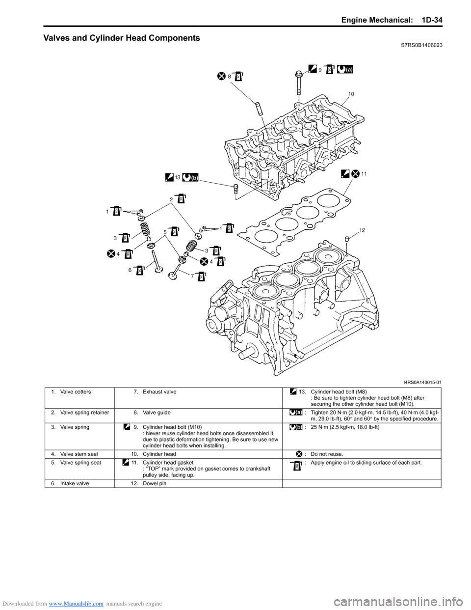
Valves and Cylinder Head ComponentsS7RS0B1406023
I4RS0A140015-01
1. Valve cotters7. Exhaust valve 13. Cylinder head bolt (M8)
: Be sure to tighten cylinder head bolt (M8) after
securing the other cylinder head bolt (M10).
2. Valve spring retainer 8. Valve guide : Tighten 20 N⋅m (2.0 kgf-m, 14.5 lb-ft), 40 N ⋅m (4.0 kgf-
m, 29.0 lb-ft), 60 ° and 60 ° by the specified procedure.
3. Valve spring 9. Cylinder head bolt (M10)
: Never reuse cylinder head bolts once disassembled it
due to plastic deformation tightening. Be sure to use new
cylinder head bolts when installing. : 25 N
⋅m (2.5 kgf-m, 18.0 lb-ft)
4. Valve stem seal 10. Cylinder head : Do not reuse.
5. Valve spring seat 11. Cylinder head gasket
: “TOP” mark provided on gasket comes to crankshaft
pulley side, facing up. : Apply engine oil to sliding surface of each part.
6. Intake valve 12. Dowel pin
Page 378 of 1496
Downloaded from www.Manualslib.com manuals search engine 1G-3 Fuel System:
4) Check that battery voltage is 11 V or more.
5) Measure fuel pressure at each condition.If measured pressure is out of specification, refer to
“Fuel Pressure Check in Section 1A” and check each
possibly defective part. Replace if found defective.
a) Turn ignition switch ON to operate fuel pump and after 2 seconds turn it OFF. Repeat this 3 or 4
times and then check fuel pressure.
Fuel pressure specification
With fuel pump operating and engine
stopped: 270 – 310 kPa (2.7 – 3.1 kg/cm2, 38.4
– 44.0 psi)
b) Start engine and warm it up to normal operating temperature, and measure fuel pressure at
idling.
Fuel pressure specification
At specified idle speed: 270 – 310 kPa (2.7 –
3.1 kg/cm2, 38.4 – 44.0 psi)
c) Stop engine, and measure fuel pressure at one minute after stopping.
Fuel pressure specification
With 1 min. after engine (fuel pump) stop
(Pressure reduces as time passes): Over 300
kPa (3.0 kg/cm
2, 42.7 psi)
6) After checking fuel pressure, remove fuel pressure gauge.
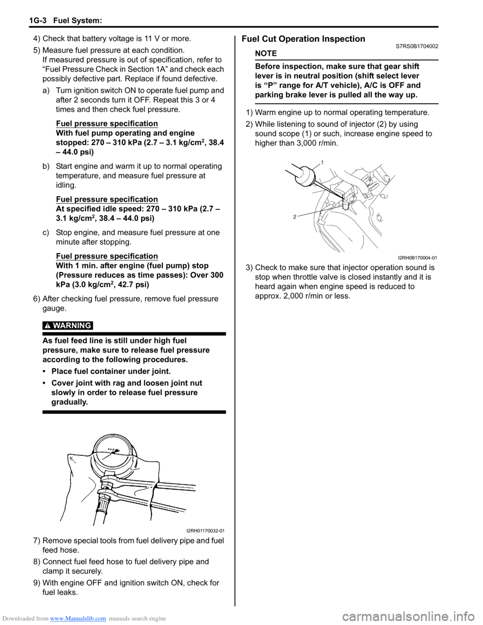
WARNING!
As fuel feed line is still under high fuel
pressure, make sure to release fuel pressure
according to the following procedures.
• Place fuel container under joint.
• Cover joint with rag and loosen joint nut slowly in order to release fuel pressure
gradually.
7) Remove special tools from fuel delivery pipe and fuel feed hose.
8) Connect fuel feed hose to fuel delivery pipe and clamp it securely.
9) With engine OFF and ignition switch ON, check for fuel leaks.
Fuel Cut Operation InspectionS7RS0B1704002
NOTE
Before inspection, make sure that gear shift
lever is in neutral positi on (shift select lever
is “P” range for A/T vehicle), A/C is OFF and
parking brake lever is pulled all the way up.
1) Warm engine up to normal operating temperature.
2) While listening to sound of injector (2) by using sound scope (1) or such, increase engine speed to
higher than 3,000 r/min.
3) Check to make sure that injector operation sound is stop when throttle valve is closed instantly and it is
heard again when engine speed is reduced to
approx. 2,000 r/min or less.
I2RH01170032-01
I2RH0B170004-01
Page 399 of 1496
Downloaded from www.Manualslib.com manuals search engine Ignition System: 1H-7
High-Tension Cord InspectionS7RS0B1806002
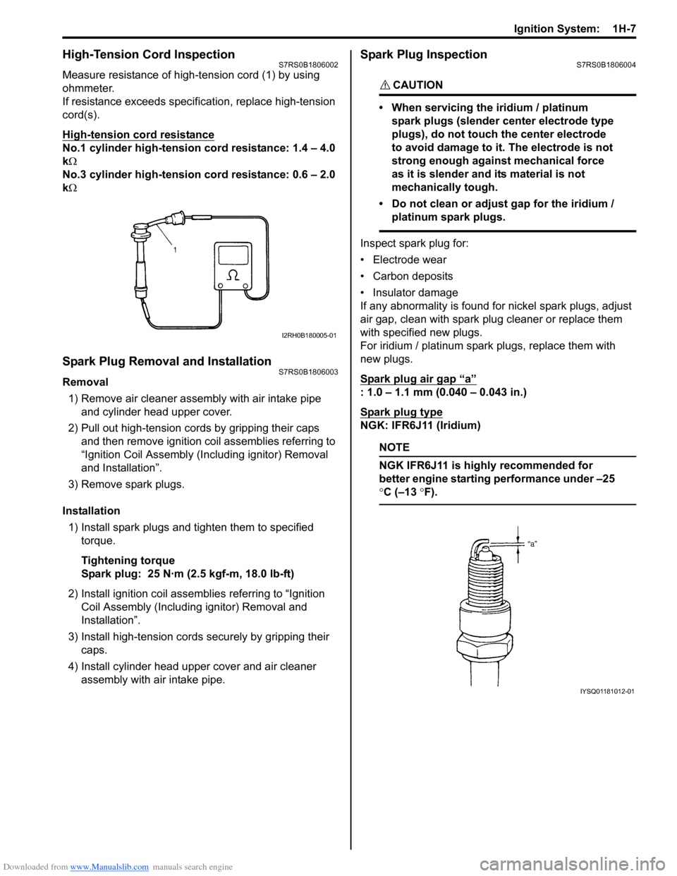
Measure resistance of high-tension cord (1) by using
ohmmeter.
If resistance exceeds specification, replace high-tension
cord(s).
High-tension cord resistance
No.1 cylinder high-tension cord resistance: 1.4 – 4.0
k Ω
No.3 cylinder high-tension cord resistance: 0.6 – 2.0
k Ω
Spark Plug Removal and InstallationS7RS0B1806003
Removal
1) Remove air cleaner assembly with air intake pipe and cylinder head upper cover.
2) Pull out high-tension cords by gripping their caps and then remove ignition coil assemblies referring to
“Ignition Coil Assembly (Inc luding ignitor) Removal
and Installation”.
3) Remove spark plugs.
Installation 1) Install spark plugs and tighten them to specified torque.
Tightening torque
Spark plug: 25 N·m (2.5 kgf-m, 18.0 lb-ft)
2) Install ignition coil assemblies referring to “Ignition Coil Assembly (Including ignitor) Removal and
Installation”.
3) Install high-tension cords securely by gripping their caps.
4) Install cylinder head upper cover and air cleaner assembly with air intake pipe.
Spark Plug InspectionS7RS0B1806004
CAUTION!
• When servicing the iridium / platinum
spark plugs (slender center electrode type
plugs), do not touch the center electrode
to avoid damage to it. The electrode is not
strong enough against mechanical force
as it is slender and its material is not
mechanically tough.
• Do not clean or adjust gap for the iridium / platinum spark plugs.
Inspect spark plug for:
• Electrode wear
• Carbon deposits
• Insulator damage
If any abnormality is found for nickel spark plugs, adjust
air gap, clean with spark plug cleaner or replace them
with specified new plugs.
For iridium / platinum spark plugs, replace them with
new plugs.
Spark plug air gap
“a”
: 1.0 – 1.1 mm (0.040 – 0.043 in.)
Spark plug type
NGK: IFR6J11 (Iridium)
NOTE
NGK IFR6J11 is highly recommended for
better engine starting performance under –25
°C (–13 °F).
I2RH0B180005-01
IYSQ01181012-01