Radio connection SUZUKI SWIFT 2007 2.G Service Workshop Manual
[x] Cancel search | Manufacturer: SUZUKI, Model Year: 2007, Model line: SWIFT, Model: SUZUKI SWIFT 2007 2.GPages: 1496, PDF Size: 34.44 MB
Page 194 of 1496

Downloaded from www.Manualslib.com manuals search engine 1A-144 Engine General Information and Diagnosis:
DTC Troubleshooting
NOTE
• When measuring circuit voltage, resistance and/or pulse signal at ECM connector, connect the
special tool to ECM and/or the ECM connectors re ferring to “Inspection of ECM and Its Circuits”.
• Upon completion of inspection and repair work, perform “DTC Confirmation Procedure” and confirm that the trouble has been corrected.
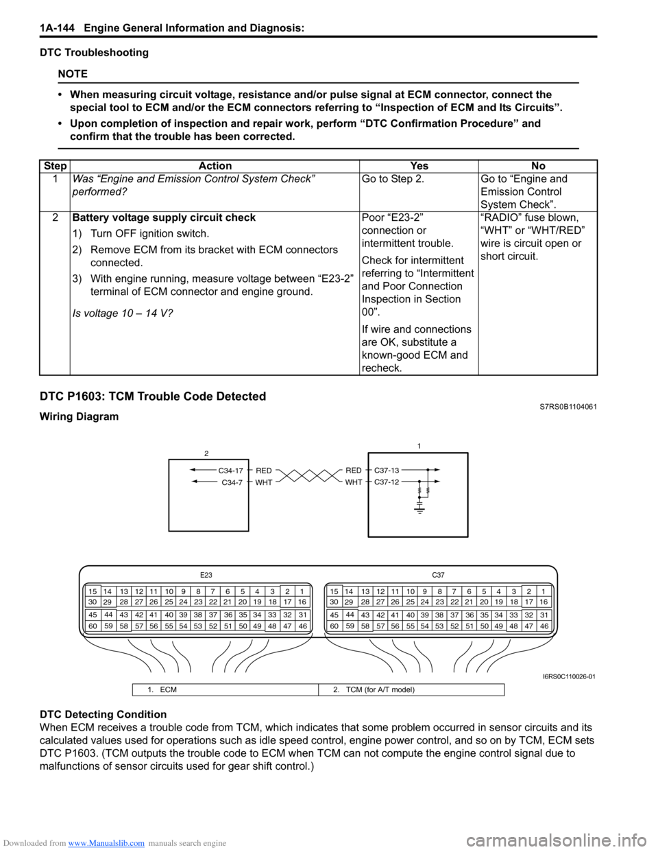
DTC P1603: TCM Trouble Code DetectedS7RS0B1104061
Wiring Diagram
DTC Detecting Condition
When ECM receives a trouble code from TCM, which indicates that some problem occurred in sensor circuits and its
calculated values used for operations such as idle speed control, engine power control, and so on by TCM, ECM sets
DTC P1603. (TCM outputs the trouble code to ECM when TCM can not compute the engine control signal due to
malfunctions of sensor circuits used for gear shift control.) Step Action Yes No
1 Was “Engine and Emission Control System Check”
performed? Go to Step 2. Go to “Engine and
Emission Control
System Check”.
2 Battery voltage supply circuit check
1) Turn OFF ignition switch.
2) Remove ECM from its br acket with ECM connectors
connected.
3) With engine running, measure voltage between “E23-2” terminal of ECM connector and engine ground.
Is voltage 10 – 14 V? Poor “E23-2”
connection or
intermittent trouble.
Check for intermittent
referring to “Intermittent
and Poor Connection
Inspection in Section
00”.
If wire and connections
are OK, substitute a
known-good ECM and
recheck.“RADIO” fuse blown,
“WHT” or “WHT/RED”
wire is circuit open or
short circuit.
E23
C37
34
1819
567
1011
17
20
47 46
495051
2122
52 16
25 9
24
14
29
55
57 54 53
59
60 58 2
262728
15
30
56 4832 31
34353637
40
42 39 38
44
45 43 41 331
1213
238
34
1819
567
1011
17
20
47 46
495051
2122
52 16
25 9
24
14
29
55
57 54 53
59
60 58 2
262728
15
30
56 4832 31
34353637
40
42 39 38
44
45 43 41 331
1213
238
1
RED
WHT
C37-13
C37-12
RED
WHTC34-7
C34-17
2
I6RS0C110026-01
1. ECM
2. TCM (for A/T model)
Page 245 of 1496

Downloaded from www.Manualslib.com manuals search engine Engine General Information and Diagnosis: 1A-195
Circuit Description
When the ignition switch is turned ON, the main relay turns ON (the contact point closes) and the main power is
supplied to ECM.
Troubleshooting
NOTE
When measuring circuit voltage, resistance and/or pulse signal at ECM connector, connect the special
tool to ECM and/or the ECM connectors referri ng to “Inspection of ECM and Its Circuits”.
StepAction YesNo
1 Circuit fuse check
1) Disconnect connectors from ECM with ignition switch
turned OFF.
2) Check for proper connection to ECM connector at “E23- 2”, “E23-29”, “E23-60”, “E23-1”, “E23-16”, “E23-31”,
“C37-58”, “C37-15” and “C37-30” terminals.
3) If OK, check “RADIO” fuse and “IG COIL” fuse for blowing.
Are “RADIO” fuse and “IG COIL” fuse in good condition? Go to Step 2.
Replace fuse (s) and
check for short in
circuits connected to
fuse(s).
2 Power supply circuit check
1) Measure voltage between “E23-2” terminal of ECM
connector and body ground.
Is voltage 10 – 14 V? Go to Step 3.
“WHT/RED” or “WHT”
wire is open circuit.
3 Ignition signal check
1) Turn ignition switch to ON position.
2) Measure voltage between “E23-29” terminal of ECM
connector and body ground.
Is voltage 10 – 14 V? Go to Step 4.
“BLK/WHT” or “GRN”
wire is open circuit.
4 Main relay circuit check
1) Turn ignition switch to OFF position.
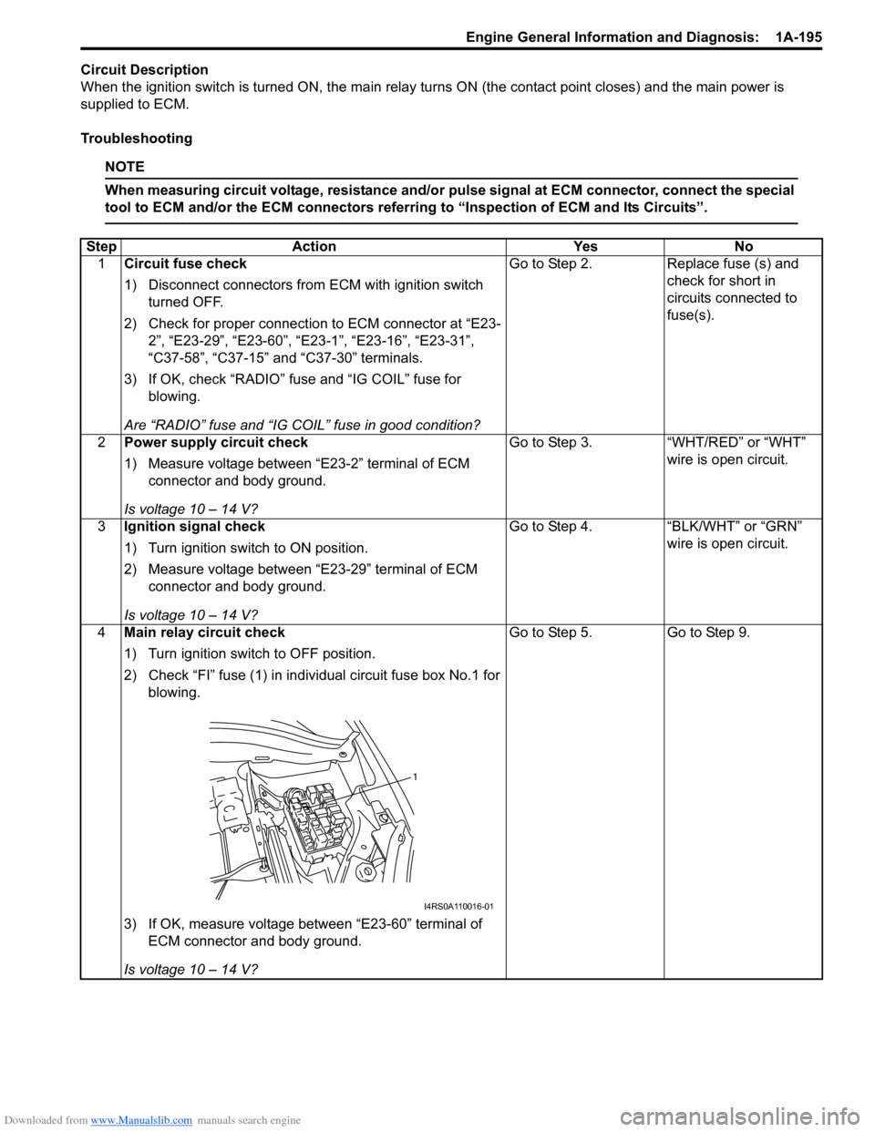
2) Check “FI” fuse (1) in indivi dual circuit fuse box No.1 for
blowing.
3) If OK, measure voltage between “E23-60” terminal of ECM connector and body ground.
Is voltage 10 – 14 V? Go to Step 5.
Go to Step 9.
1
I4RS0A110016-01
Page 1471 of 1496

Downloaded from www.Manualslib.com manuals search engine Keyless Start System: 10E-9
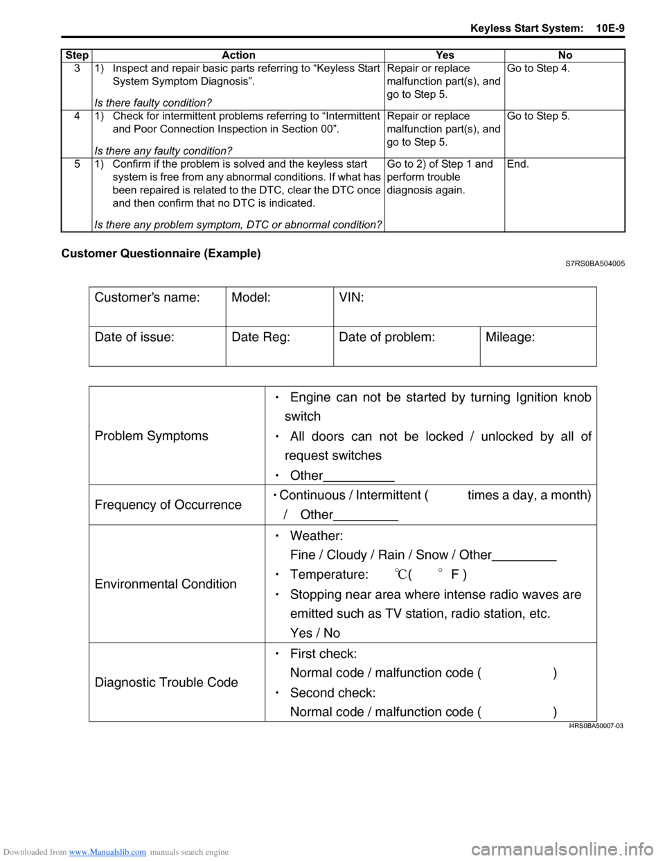
Customer Questionnaire (Example)S7RS0BA504005
3 1) Inspect and repair basic parts referring to “Keyless Start System Symptom Diagnosis”.
Is there faulty condition? Repair or replace
malfunction part(s), and
go to Step 5.
Go to Step 4.
4 1) Check for intermittent problems referring to “Intermittent and Poor Connection Inspection in Section 00”.
Is there any faulty condition? Repair or replace
malfunction part(s), and
go to Step 5.
Go to Step 5.
5 1) Confirm if the problem is solved and the keyless start system is free from any abnormal conditions. If what has
been repaired is related to the DTC, clear the DTC once
and then confirm that no DTC is indicated.
Is there any problem symptom, DTC or abnormal condition? Go to 2) of Step 1 and
perform trouble
diagnosis again.
End.
Step Action Yes No
Customers name:
Model:
VIN:
Date of issue:
Date Reg:
Date of problem:
Mileage:
Problem Symptoms
Engine can not be started by turning Ignition knob
switch
All doors can not be locked / unlocked by all of
request switches
Other
Frequency of Occurrence Continuous / Intermittent ( times a day, a month)
/ Other
Environmental Condition
Weather:
Fine / Cloudy / Rain / Snow / Other
Temperature: (F )
Stopping near area where intense radio waves are
emitted such as TV station, radio station, etc.
Yes / No
Diagnostic Trouble Code
First check:
Normal code / malfunction code ( )
Second check:
Normal code / malfunction code ( )
I4RS0BA50007-03