Screen SUZUKI SWIFT 2007 2.G Service Workshop Manual
[x] Cancel search | Manufacturer: SUZUKI, Model Year: 2007, Model line: SWIFT, Model: SUZUKI SWIFT 2007 2.GPages: 1496, PDF Size: 34.44 MB
Page 359 of 1496
Downloaded from www.Manualslib.com manuals search engine Engine Lubrication System: 1E-7
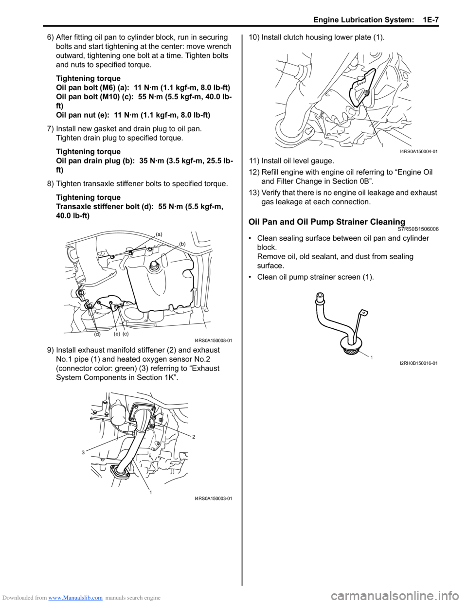
6) After fitting oil pan to cylinder block, run in securing bolts and start tightening at the center: move wrench
outward, tightening one bolt at a time. Tighten bolts
and nuts to specified torque.
Tightening torque
Oil pan bolt (M6) (a): 11 N·m (1.1 kgf-m, 8.0 lb-ft)
Oil pan bolt (M10) (c): 55 N·m (5.5 kgf-m, 40.0 lb-
ft)
Oil pan nut (e): 11 N·m (1.1 kgf-m, 8.0 lb-ft)
7) Install new gasket and drain plug to oil pan. Tighten drain plug to specified torque.
Tightening torque
Oil pan drain plug (b): 35 N·m (3.5 kgf-m, 25.5 lb-
ft)
8) Tighten transaxle stiffener bolts to specified torque. Tightening torque
Transaxle stiffener bolt (d): 55 N·m (5.5 kgf-m,
40.0 lb-ft)
9) Install exhaust manifold stiffener (2) and exhaust No.1 pipe (1) and heated oxygen sensor No.2
(connector color: green) (3) referring to “Exhaust
System Components in Section 1K”. 10) Install clutch housing lower plate (1).
11) Install oil level gauge.
12) Refill engine with engine oil referring to “Engine Oil
and Filter Change in Section 0B”.
13) Verify that there is no en gine oil leakage and exhaust
gas leakage at each connection.
Oil Pan and Oil Pump Strainer CleaningS7RS0B1506006
• Clean sealing surface between oil pan and cylinder block.
Remove oil, old sealant, and dust from sealing
surface.
• Clean oil pump strainer screen (1).(a)
(b)
(c)(e)
(d)I4RS0A150008-01
2
1
3
I4RS0A150003-01
1I4RS0A150004-01
I2RH0B150016-01
Page 958 of 1496

Downloaded from www.Manualslib.com manuals search engine 7B-10 Air Conditioning System: Manual Type
Abnormal Noise from Tension Pulley
Abnormal Noise from A/C Evaporator
Abnormal Noise from Blower Motor
A/C System Performance InspectionS7RS0B7214003
1) Confirm that vehicle and environmental conditions are as follows.
• Vehicle is put indoors.
• Ambient temperature is within 25 – 35 °C (77 – 95
° F).
• Relative humidity is within 30 – 70%.
• There is no wind indoors.
• HVAC unit is normal.
• Blower motor is normal.
• There is no air leakage from air ducts.
• Condenser fins are clean.
• Air filter in HVAC unit is not clogged with dirt and
dust.
• Battery voltage is about 12 V.
• Radiator cooling fan operates normally.
2) Make sure that high pressure valve (1) and low pressure valve (2) of manifold gauge are firmly
closed.
3) Connect high pressure charging hose (3) to high pressure service valve (5) on vehicle and low
pressure charging hose (4) to low pressure service
valve (6).
4) Bleed the air in charging hoses (3) and (4) by loosening their nuts respectively utilizing the
refrigerant pressure. When a hissing sound is heard,
immediately tighten nut.
CAUTION!
Do not connect high and low pressure
charging hoses in reverse.
Condition Possible cause Correction / Reference Item
Clattering noise is heard
from pulley Worn or damaged bearing
Replace tension pulley.
Pulley cranks upon
contact Cracked or loose bracket
Replace or retighten bracket.
ConditionPossible cause Correction / Reference Item
Whistling sound is heard
from A/C evaporator Depending on the combination of the
interior / exterior temperatures, engine
rpm and refrigerant pressure, the
refrigerant flowing out of the expansion
valve may, under certain conditions,
make a whistling sound At times, slightly decrea
sing refrigerant volume
may stop this noise.
Inspect expansion valve and replace if faulty.
Condition Possible cause Correction / Reference Item
Blower motor emits a
chirping sound in
proportion to its speed of
rotation Worn or damaged motor brushes or
commutator
Replace blower motor.
Fluttering noise or large
droning noise is heard
from blower motor Leaves or other debris introduced from
fresh air inlet to blower motor
Remove debris and make sure that the screen
at fresh air inlet is intact.
53
2
1
4 6
I4RS0A720006-01
Page 1168 of 1496

Downloaded from www.Manualslib.com manuals search engine 9-ii Table of Contents
List of Connectors ........................................... 9A-103
C Connector .................................................... 9A-103
D Connector (M16A engine) ........................... 9A-104
E Connector .................................................... 9A-104
G Connector .................................................... 9A-106
J Connector ..................................................... 9A-108
K Connector .................................................... 9A-109
L Connector..................................................... 9A-109
M Connector (SPORT model) ......................... 9A-111
O Connector .................................................... 9A-111
R Connector .................................................... 9A-111
Lighting Systems .................................... 9B-1
Component Location ........... ................................9B-1
Lighting System Component s Location............... 9B-1
Interior Light System Location............................. 9B-2
Diagnostic Information and Procedures ............ 9B-2 Headlight Symptom Diagnosis ............................ 9B-2
Headlight Leveling System Symptom Diagnosis (If Equipped) ..................................... 9B-2
Turn Signal and Hazard Warning Light Symptom Diagnosis .......................................... 9B-3
Clearance, Tail and License Plate Light Symptom Diagnosis .......................................... 9B-3
Back-Up Light Symptom Diagnosis..................... 9B-4
Brake Light Symptom Diagnosis ......................... 9B-4
Front Fog Light Symptom Diagnosis (If Equipped) .......................................................... 9B-4
Interior Light Symptom Diagnosis ....................... 9B-5
Repair Instructions ..............................................9B-5 Headlight Housing Removal and Installation ...... 9B-5
Headlight Bulb Replacemen t............................... 9B-6
Headlight Aiming Adjustment with Screen .......... 9B-6
Headlight Switch (in Lighting Switch) Removal and Installation ................................... 9B-8
Headlight Switch (in Lighting Switch) Inspection .......................................................... 9B-8
Hazard Warning Switch Removal and Installation ......................................................... 9B-8
Hazard Warning Switch Inspection ..................... 9B-9
Brake Light Switch Inspection ............................. 9B-9
Turn Signal Light Switch (in Lighting Switch) Removal and Installation ................................... 9B-9
Turn Signal Light Switch (in Lighting Switch) Inspection .......................................................... 9B-9
Turn Signal and Hazard Warning Relay Removal and Installation ................................... 9B-9
Turn Signal and Hazard Warning Relay Inspection ........................................................ 9B-10
License Light Removal and Installation............. 9B-10
Front Fog Light Removal and Installation (If Equipped) ........................................................ 9B-11
Front Fog Light Bulb Replacement (If Equipped) ........................................................ 9B-11
Front Fog Light Switch Inspection (If Equipped) ........................................................ 9B-11
Front Fog Light Relay Inspection (If Equipped) ........................................................ 9B-11
Front Fog Light Aiming Adjustment with Screen (If Equipped) ....................................... 9B-12 Headlight Leveling Switch Inspection (If
Equipped) ........................................................ 9B-13
Headlight Leveling Actuator Inspection (If Equipped) ........................................................ 9B-13
Instrumentation / Driver Info. / Horn ...... 9C-1
Precautions ...........................................................9C-1 Precautions in Diagnosing Troubles for Combination Meter ............................................9C-1
General Description .............................................9C-1 CAN Communication System Description...........9C-1
Auto Volume Co ntrol System Description (If
Equipped) ..........................................................9C-3
Schematic and Routing Diagram ........................9C-4 Combination Meter Circuit Diagram ....................9C-4
Component Location ............ ...............................9C-6
Audio System Component Location ....................9C-6
Diagnostic Information and Procedures ............9C-6 Speedometer and VSS Symp tom Diagnosis ......9C-6
Tachometer Symptom Diagnosis ........................9C-6
Engine Coolant Temperature (ECT) Meter Symptom Diagnosis ..........................................9C-7
Fuel Meter Symptom Diagnosis ..........................9C-7
Low Fuel Warning Light Symptom Diagnosis .....9C-7
Oil Pressure Warning Light Symptom Diagnosis ..........................................................9C-8
Brake and Parking Brake Warning Light Symptom Diagnosis ..........................................9C-8
Seat Belt Reminder Light Symptom Diagnosis (If Equipped)......................................................9C-8
A/T Shift Position Indicator Symptom Diagnosis (A/T Model).......................................9C-9
Charge Warning Light Sy mptom Diagnosis ........9C-9
Main Beam (High Beam) Indicator Symptom Diagnosis ..........................................................9C-9
Warning Buzzer Circuit Sy mptom Diagnosis ....9C-10
Cigarette Lighter Symptom Diagnosis (If Equipped) ........................................................9C-10
Horn Symptom Diagnosis .................................9C-10
Information Display Symptom Diagnosis (If Equipped) ........................................................9C-11
Clock Symptom Diagnosis (If Equipped)...........9C-12
Audio System Symptom Diagnosis (If Equipped) ........................................................9C-12
Remote Audio Control Switch Symptom Diagnosis (If Equipped) ...................................9C-13
Navigation Symptom Diagnosis (If Equipped)...9C-14
Repair Instructions ............ ................................9C-14
Ignition Switch Removal and Installation...........9C-14
Ignition Switch Inspection..................................9C-14
Combination Meter Removal and Installation ...9C-15
Fuel Level Sensor Removal and Installation .....9C-15
Fuel Level Sensor Inspection ............................9C-15
Oil Pressure Switch Remova l and Installation ..9C-15
Oil Pressure Switch Inspec tion .........................9C-16
Engine Coolant Temperature (ECT) Sensor Inspection ........................................................9C-16
Brake Fluid Level Switch Inspection .................9C-16
Parking Brake Switch Inspec tion.......................9C-16
Page 1287 of 1496
Downloaded from www.Manualslib.com manuals search engine Lighting Systems: 9B-5
Interior Light Symptom DiagnosisS7RS0B9204008
NOTE
• Use of SUZUKI scan tool makes it easy to check whether a faulty condition is on the input side or
output side of BCM. For checking procedure, re fer to “Diagnosis Using Output Test Function of
SUZUKI Scan Tool” under “Scan Tool Data in Section 10B”.
• Check each part in the order from the top of the following list.
Repair Instructions
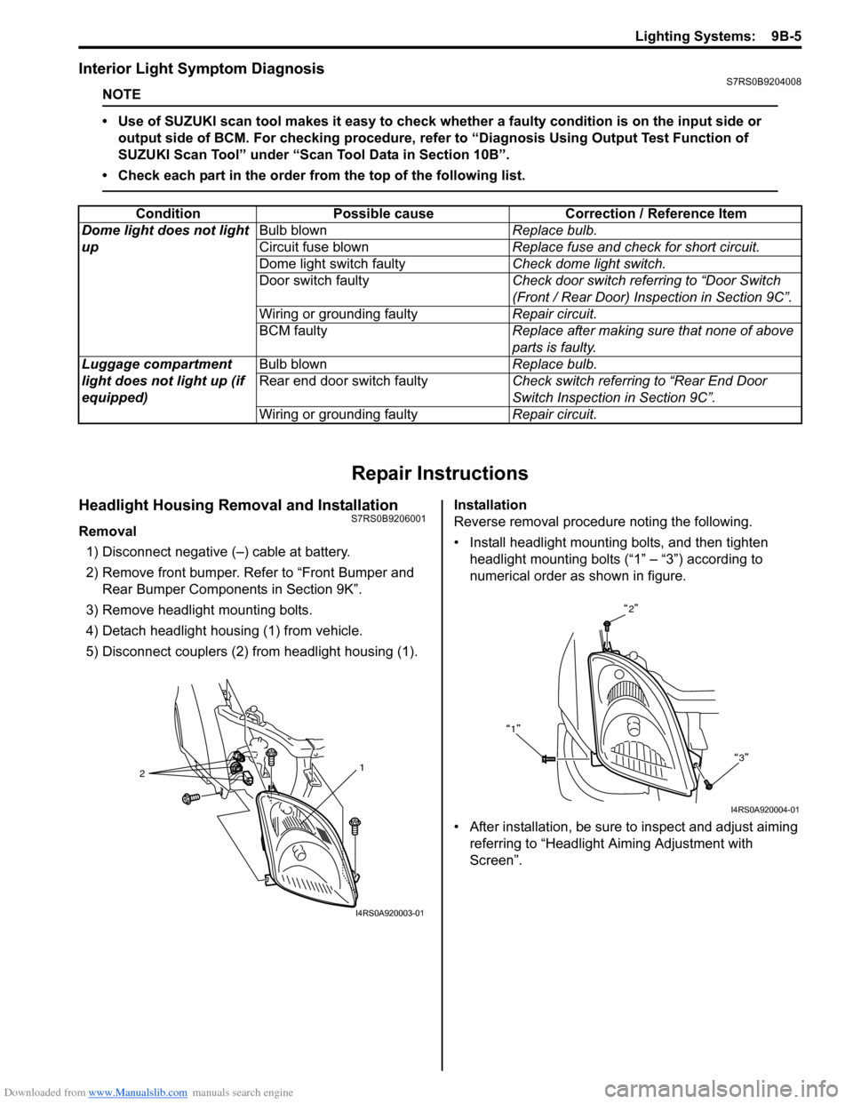
Headlight Housing Removal and InstallationS7RS0B9206001
Removal 1) Disconnect negative (–) cable at battery.
2) Remove front bumper. Refer to “Front Bumper and Rear Bumper Componen ts in Section 9K”.
3) Remove headlight mounting bolts.
4) Detach headlight housing (1) from vehicle.
5) Disconnect couplers (2) from headlight housing (1). Installation
Reverse removal procedure noting the following.
• Install headlight mounting bolts, and then tighten
headlight mounting bolts (“1” – “3”) according to
numerical order as shown in figure.
• After installation, be sure to inspect and adjust aiming referring to “Headlight Aiming Adjustment with
Screen”.
Condition Possible cause Correction / Reference Item
Dome light does not light
up Bulb blown
Replace bulb.
Circuit fuse blown Replace fuse and check for short circuit.
Dome light switch faulty Check dome light switch.
Door switch faulty Check door switch referring to “Door Switch
(Front / Rear Door) Inspection in Section 9C”.
Wiring or grounding faulty Repair circuit.
BCM faulty Replace after making sure that none of above
parts is faulty.
Luggage compartment
light does not light up (if
equipped) Bulb blown
Replace bulb.
Rear end door switch faulty Check switch referring to “Rear End Door
Switch Inspection in Section 9C”.
Wiring or grounding faulty Repair circuit.
2 1
I4RS0A920003-01
2
1 3
I4RS0A920004-01
Page 1288 of 1496
Downloaded from www.Manualslib.com manuals search engine 9B-6 Lighting Systems:
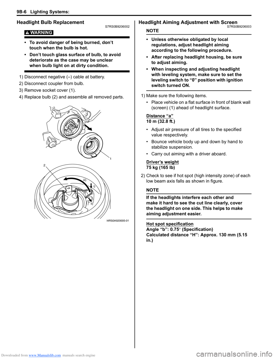
Headlight Bulb ReplacementS7RS0B9206002
WARNING!
• To avoid danger of being burned, don’t touch when the bulb is hot.
• Don’t touch glass surface of bulb, to avoid deteriorate as the case may be unclear
when bulb light on at dirty condition.
1) Disconnect negative (–) cable at battery.
2) Disconnect coupler from bulb.
3) Remove socket cover (1).
4) Replace bulb (2) and assemble all removed parts.
Headlight Aiming Adjustment with ScreenS7RS0B9206003
NOTE
• Unless otherwise obligated by local regulations, adjust headlight aiming
according to the following procedure.
• After replacing headlight housing, be sure to adjust aiming.
• When inspecting and adjusting headlight with leveling system, make sure to set the
leveling switch to “0 ” position with ignition
switch turned ON.
1) Make sure the following items.
• Place vehicle on a flat surface in front of blank wall (screen) (1) ahead of headlight surface.
Distance “a”
10 m (32.8 ft.)
• Adjust air pressure of all tires to the specified value respectively.
• Bounce vehicle body up and down by hand to stabilize suspension.
• Carry out aiming with a driver aboard.
Driver’s weight
75 kg (165 lb)
2) Check to see if hot spot (high intensity zone) of each low beam axis falls as shown in figure.
NOTE
If the headlights interfere each other and
make it hard to see the cut line clearly, cover
the headlight on one side. This helps to make
aiming adjustment easier.
Hot spot specification
Angle “b”: 0.75 ° (Specification)
Calculated distance “H”: Approx. 130 mm (5.15
in.)
1
iii)
2
i)
ii)
I4RS0A920005-01
Page 1293 of 1496
Downloaded from www.Manualslib.com manuals search engine Lighting Systems: 9B-11
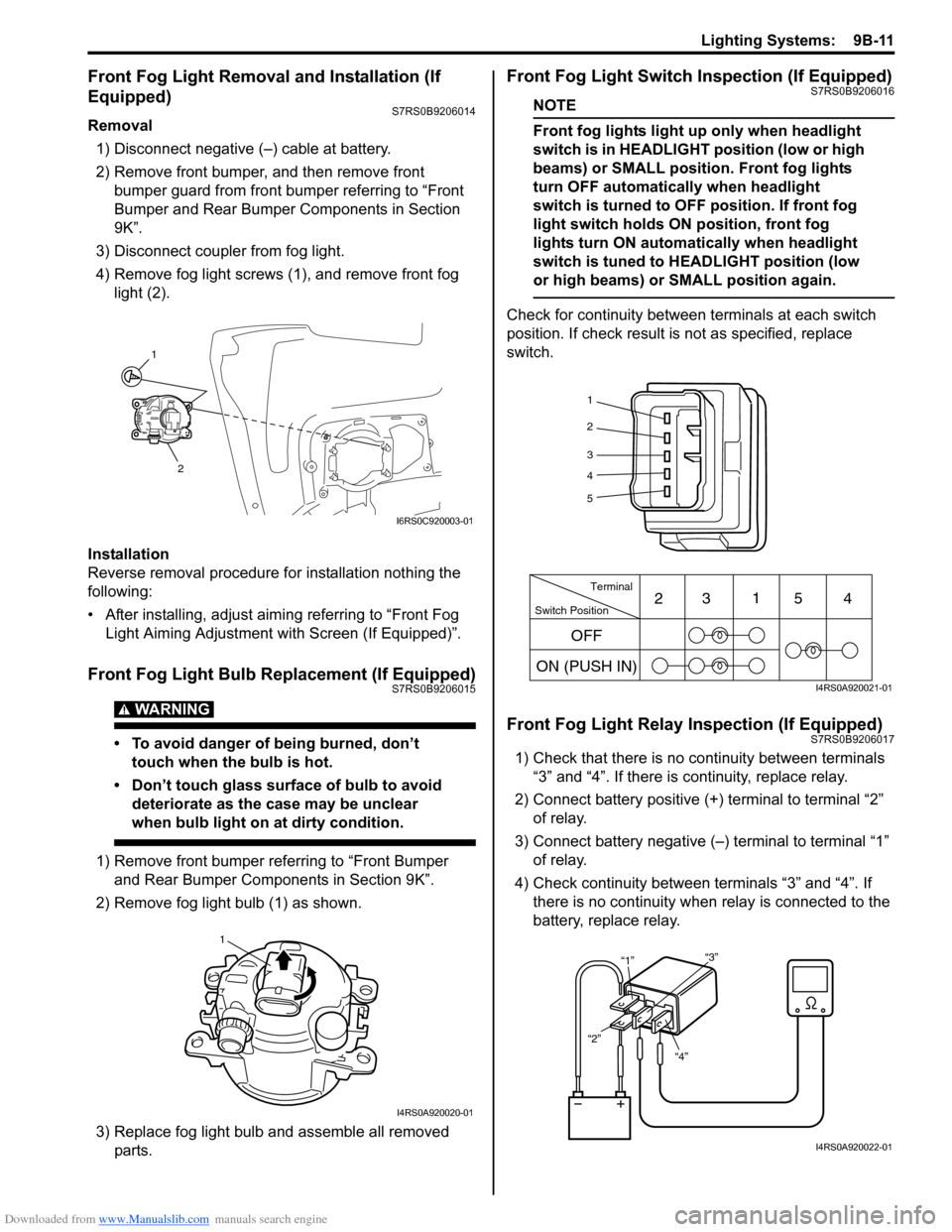
Front Fog Light Removal and Installation (If
Equipped)
S7RS0B9206014
Removal1) Disconnect negative (–) cable at battery.
2) Remove front bumper, and then remove front bumper guard from front bumper referring to “Front
Bumper and Rear Bumper Components in Section
9K”.
3) Disconnect coupler from fog light.
4) Remove fog light screws (1), and remove front fog light (2).
Installation
Reverse removal procedure for installation nothing the
following:
• After installing, adjust aimi ng referring to “Front Fog
Light Aiming Adjustment with Screen (If Equipped)”.
Front Fog Light Bulb Replacement (If Equipped)S7RS0B9206015
WARNING!
• To avoid danger of being burned, don’t touch when the bulb is hot.
• Don’t touch glass surface of bulb to avoid deteriorate as the case may be unclear
when bulb light on at dirty condition.
1) Remove front bumper referring to “Front Bumper and Rear Bumper Components in Section 9K”.
2) Remove fog light bulb (1) as shown.
3) Replace fog light bulb and assemble all removed parts.
Front Fog Light Switch Inspection (If Equipped)S7RS0B9206016
NOTE
Front fog lights light up only when headlight
switch is in HEADLIGHT position (low or high
beams) or SMALL position. Front fog lights
turn OFF automatically when headlight
switch is turned to OFF position. If front fog
light switch holds ON position, front fog
lights turn ON automa tically when headlight
switch is tuned to HEADLIGHT position (low
or high beams) or SMALL position again.
Check for continuity between terminals at each switch
position. If check result is not as specified, replace
switch.
Front Fog Light Relay Inspection (If Equipped)S7RS0B9206017
1) Check that there is no continuity between terminals “3” and “4”. If there is continuity, replace relay.
2) Connect battery positive (+ ) terminal to terminal “2”
of relay.
3) Connect battery negative (–) terminal to terminal “1” of relay.
4) Check continuity between terminals “3” and “4”. If there is no continuity when relay is connected to the
battery, replace relay.
1
2
I6RS0C920003-01
1
I4RS0A920020-01
1
2
3
4
5
Switch Position Terminal
ON (PUSH IN) 23
1
54
OFF
I4RS0A920021-01
“4”
“2” “1”
“3”
I4RS0A920022-01
Page 1294 of 1496
Downloaded from www.Manualslib.com manuals search engine 9B-12 Lighting Systems:
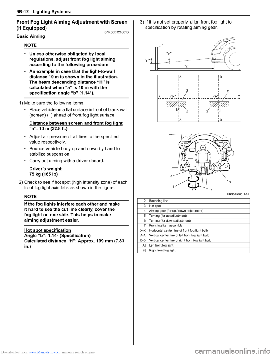
Front Fog Light Aiming Adjustment with Screen
(If Equipped)
S7RS0B9206018
Basic Aiming
NOTE
• Unless otherwise obligated by local regulations, adjust front fog light aiming
according to the following procedure.
• An example in case that the light-to-wall distance 10 m is shown in the illustration.
The beam descending distance “H” is
calculated when “a” is 10 m with the
specification angle “b” (1.14 °).
1) Make sure the following items.
• Place vehicle on a flat surface in front of blank wall (screen) (1) ahead of front fog light surface.
Distance between screen and front fog light
“a”: 10 m (32.8 ft.)
• Adjust air pressure of all tires to the specified value respectively.
• Bounce vehicle body up and down by hand to stabilize suspension.
• Carry out aiming with a driver aboard.
Driver’s weight
75 kg (165 lb)
2) Check to see if hot spot (h igh intensity zone) of each
front fog light axis falls as shown in the figure.
NOTE
If the fog lights interfere each other and make
it hard to see the cut line clearly, cover the
fog light on one side. This helps to make
aiming adjustment easier.
Hot spot specification
Angle “b”: 1.14° (Specification)
Calculated distance “H”: Approx. 199 mm (7.83
in.) 3) If it is not set properly
, align front fog light to
specification by rotating aiming gear.
2. Bounding line
3. Hot spot
4. Aiming gear (for up / down adjustment)
5. Turning (for up adjustment)
6. Turning (for down adjustment)
7. Front fog light assembly
X-X: Horizontal center line of front fog light bulb
A-A: Vertical center line of left front fog light bulb
B-B: Vertical center line of right front fog light bulb [A]: Left front fog light
[B]: Right front fog light
I4RS0B920011-01
Page 1295 of 1496
Downloaded from www.Manualslib.com manuals search engine Lighting Systems: 9B-13
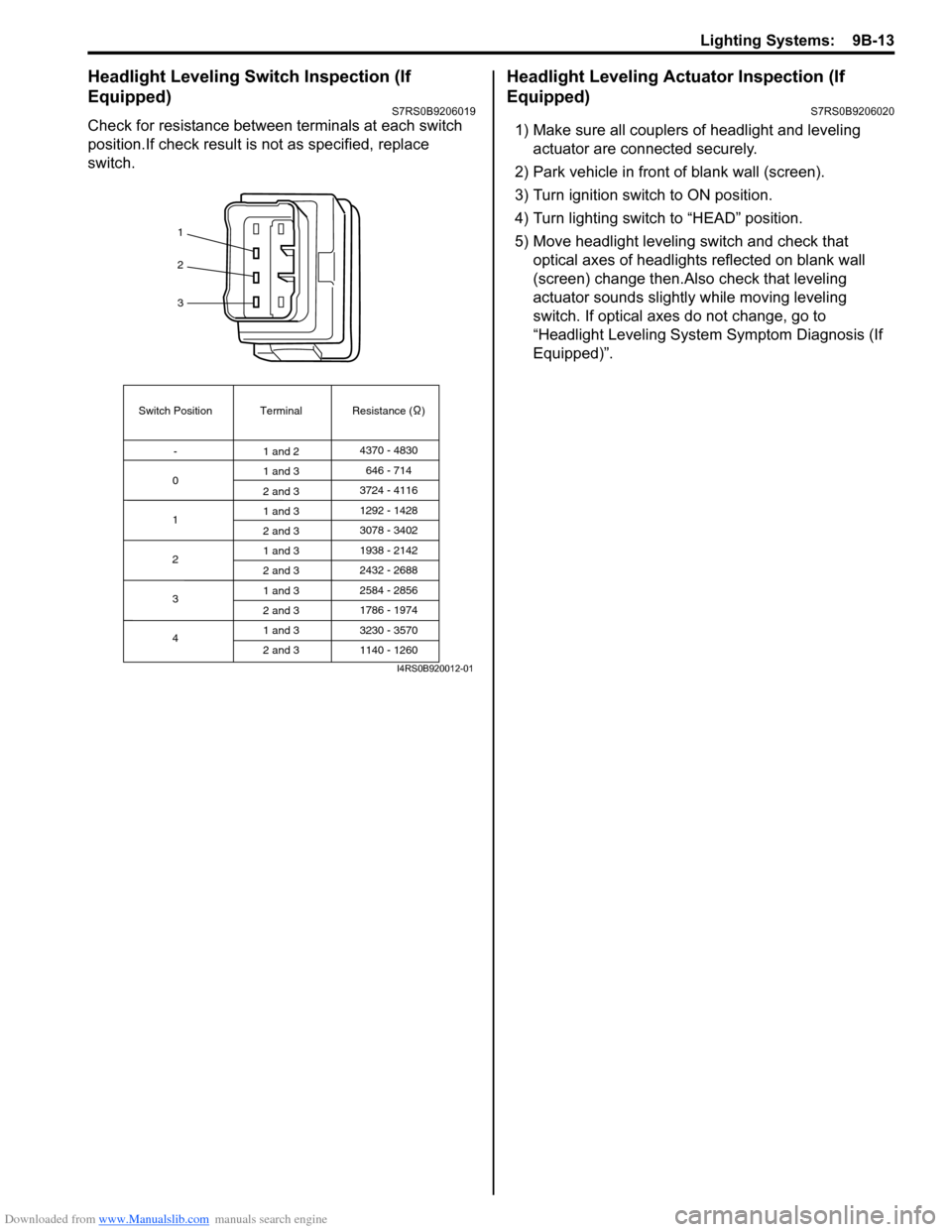
Headlight Leveling Switch Inspection (If
Equipped)
S7RS0B9206019
Check for resistance between terminals at each switch
position.If check result is not as specified, replace
switch.
Headlight Leveling Actuator Inspection (If
Equipped)
S7RS0B9206020
1) Make sure all couplers of headlight and leveling actuator are connected securely.
2) Park vehicle in front of blank wall (screen).
3) Turn ignition switch to ON position.
4) Turn lighting switch to “HEAD” position.
5) Move headlight leveling switch and check that
optical axes of headlights reflected on blank wall
(screen) change then.Also check that leveling
actuator sounds slightly while moving leveling
switch. If optical axes do not change, go to
“Headlight Leveling System Symptom Diagnosis (If
Equipped)”.
1
2
3
Switch Position
0 Terminal Resistance ( )
-
1
2
3
4 1 and 2
4370 - 4830
1 and 3
2 and 3
1 and 3
2 and 3
1 and 3
2 and 3
1 and 3
2 and 3
1 and 3
2 and 3 646 - 714
3724 - 4116
3078 - 3402 1292 - 1428
1938 - 2142
2584 - 2856
3230 - 3570 2432 - 2688
1786 - 1974
1140 - 1260
I4RS0B920012-01