Splash SUZUKI SWIFT 2007 2.G Service Workshop Manual
[x] Cancel search | Manufacturer: SUZUKI, Model Year: 2007, Model line: SWIFT, Model: SUZUKI SWIFT 2007 2.GPages: 1496, PDF Size: 34.44 MB
Page 385 of 1496

Downloaded from www.Manualslib.com manuals search engine Fuel System: 1G-10
4) Install suitable vinyl tube onto injector nozzle to
prevent fuel from splashing out when injecting.
5) Put graduated cylinder under injector.
6) Operate fuel pump and apply fuel pressure to
injector as follows:
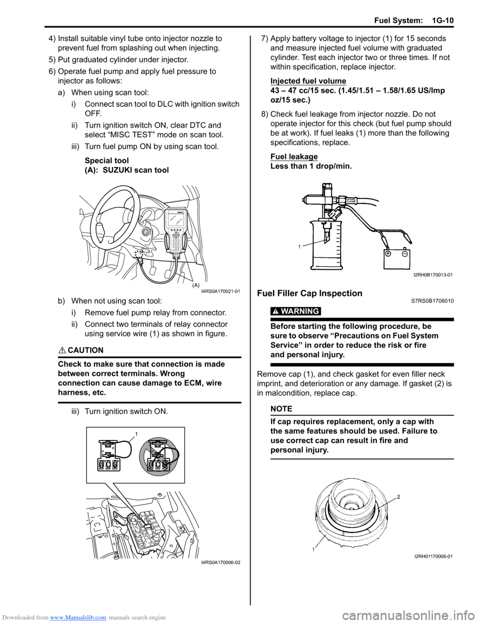
a) When using scan tool:
i) Connect scan tool to DLC with ignition switch OFF.
ii) Turn ignition switch ON, clear DTC and select “MISC TEST” mode on scan tool.
iii) Turn fuel pump ON by using scan tool.
Special tool
(A): SUZUKI scan tool
b) When not using scan tool: i) Remove fuel pump relay from connector.
ii) Connect two terminals of relay connector using service wire (1) as shown in figure.
CAUTION!
Check to make sure that connection is made
between correct terminals. Wrong
connection can cause damage to ECM, wire
harness, etc.
iii) Turn ignition switch ON. 7) Apply battery voltage to in
jector (1) for 15 seconds
and measure injected fuel volume with graduated
cylinder. Test each injector two or three times. If not
within specification, replace injector.
Injected fuel volume
43 – 47 cc/15 sec. (1.45/1.51 – 1.58/1.65 US/lmp
oz/15 sec.)
8) Check fuel leakage from injector nozzle. Do not operate injector for this check (but fuel pump should
be at work). If fuel leaks (1) more than the following
specifications, replace.
Fuel leakage
Less than 1 drop/min.
Fuel Filler Cap InspectionS7RS0B1706010
WARNING!
Before starting the following procedure, be
sure to observe “Precautions on Fuel System
Service” in order to reduce the risk or fire
and personal injury.
Remove cap (1), and che ck gasket for even filler neck
imprint, and deterioration or any damage. If gasket (2) is
in malcondition, replace cap.
NOTE
If cap requires replacement, only a cap with
the same features should be used. Failure to
use correct cap can result in fire and
personal injury.
(A)I4RS0A170021-01
1
I4RS0A170006-02
I2RH0B170013-01
I2RH01170008-01
Page 949 of 1496

Downloaded from www.Manualslib.com manuals search engine Air Conditioning System: Manual Type 7B-1
HVAC
Air Conditioning System
Manual Type
Precautions
A/C System CautionS7RS0B7210001
CAUTION!
• The air conditioning system of this vehicle uses refrigerant HFC-134a (R-134a).
None of refrigerant, compressor oil and component parts is interchangeable between two types of
A/C: one using refrigerant HFC-134a (R-134a) and the other using refrigerant CFC-12 (R-12).
Be sure to check which refrigerant is used be fore any service work including inspection and
maintenance. For identification between these two types, refer to “Refrigerant Type Identification”.
When replenishing or changing refrigerant and comp ressor oil and when replacing parts, make sure
that the material or the part to be used is appropriate to the A/C installed in the vehicle being
serviced.
Use of incorrect one will result in leakage of refrigerant, damage in parts or other faulty condition.
• When servicing the compressor, keep dirt or foreign material away from getting on or into the compressor parts and system. Clean tools and a clean work area are important for proper service.
The compressor connection and the outside of the compressor should be cleaned before any “On
vehicle” repair or before removal of the compressor. The parts must be kept clean at all times and
any parts to be reassembled should be cleaned with trichloromethane, naphtha, kerosene or
equivalent solvent and dried with dry air. Use only lint free cloths to wipe parts.
• When compressor is removed from the vehicle for servicing, the oil remaining in the compressor
should be discarded and new refrigerant oil added to the compressor.
Minor repair procedures may be done on the vehicle without discharging the system. Major repair
procedures require that the system be discharged of refrigerant.
Precautions on Servicing A/C SystemS7RS0B7210002
WARNING!
Should refrigerant HFC-134a (R-134a) is exposed to your eye(s), consult a doctor immediately.
• Do not use your hand to rub affected eye(s). Instead, use fresh cold water to splash it over affected area to thus gradually raise its temperature above the freezing point.
• Obtain proper treatment as soon as possible from a doctor or eye specialist. Should liquid refrigerant HFC-134a (R-134a) is exposed to your skin, such affected part should be treated in the
same manner as when skin is frostbitten or frozen.
Handling Refrigerant HFC-134a (R-134a)
• Always wear goggles to protect your eyes.
• Avoid direct contact to liquid refrigerant.
• Do not heat refrigerant container higher than 40 °C (104 ° F).
• Do not discharge refrigerant into atmosphere.
• Do not expose bright metals to liquid refrigerant. Refrig erant combined with moisture is corrosive and tarnishes
surfaces of bright metals including chrome.
Page 964 of 1496

Downloaded from www.Manualslib.com manuals search engine 7B-16 Air Conditioning System: Manual Type
Repair Instructions
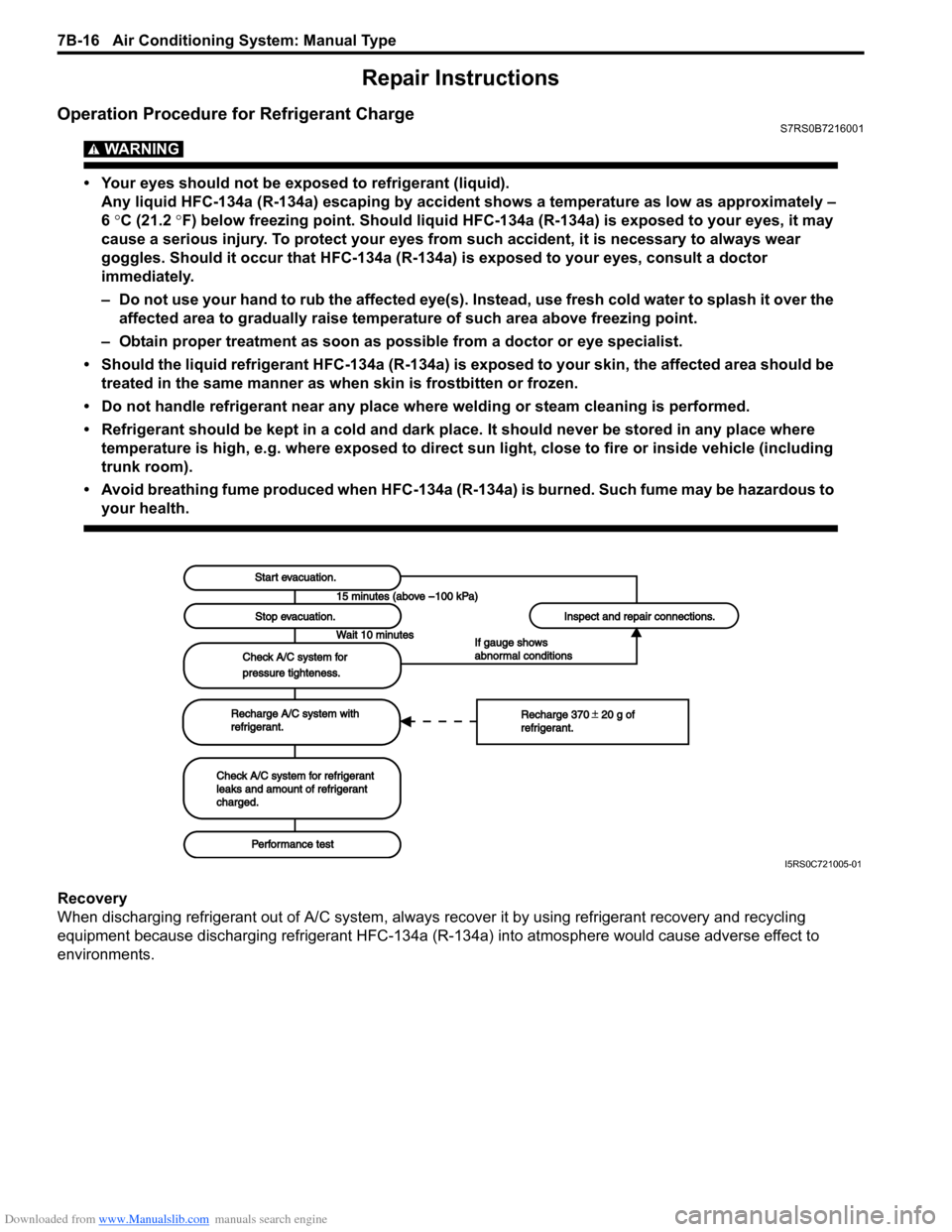
Operation Procedure for Refrigerant ChargeS7RS0B7216001
WARNING!
• Your eyes should not be exposed to refrigerant (liquid).Any liquid HFC-134a (R-134a) escaping by accident shows a temperature as low as approximately –
6 °C (21.2 ° F) below freezing point. Should liquid HFC-134a (R-134a) is exposed to your eyes, it may
cause a serious injury. To protect your eyes from such accident, it is necessary to always wear
goggles. Should it occur that HFC-134a (R-134a) is exposed to your eyes, consult a doctor
immediately.
– Do not use your hand to rub the affected eye(s). Instead, use fresh cold water to splash it over the affected area to gradually raise temperature of such area above freezing point.
– Obtain proper treatment as soon as possible from a doctor or eye specialist.
• Should the liquid refrigerant HFC-134a (R-134a) is exposed to your skin, the affected area should be treated in the same manner as when skin is frostbitten or frozen.
• Do not handle refrigerant near any place where welding or steam cleaning is performed.
• Refrigerant should be kept in a cold and dark pl ace. It should never be stored in any place where
temperature is high, e.g. where exposed to direct su n light, close to fire or inside vehicle (including
trunk room).
• Avoid breathing fume produced when HFC-134a (R-134a) is burned. Such fume may be hazardous to your health.
Recovery
When discharging refrigerant out of A/C system, always recover it by using refrigerant recovery and recycling
equipment because discharging refrigerant HFC-134a (R-1 34a) into atmosphere would cause adverse effect to
environments.
Start evacuation.Start evacuation.
Stop evacuation.Stop evacuation.
Wait 10 minutesWait 10 minutes
Check A/C system forCheck A/C system for
pressure tighteness.pressure tighteness.
Recharge A/C system withRecharge A/C system withrefrigerant.refrigerant.
Check A/C system for refrigerantCheck A/C system for refrigerantleaks and amount of refrigerantleaks and amount of refrigerantcharged.charged.
Performance testPerformance test
Inspect and repair connections.Inspect and repair connections.
If gauge showsIf gauge showsabnormal conditionsabnormal conditions
Recharge 370 20 g ofRecharge 370 20 g ofrefrigerant.refrigerant.
I5RS0C721005-01
Page 1170 of 1496

Downloaded from www.Manualslib.com manuals search engine 9-iv Table of Contents
Rear End Door Opener System Symptom Diagnosis .......................................................... 9F-5
Rear End Door Opener System Operation Inspection .......................................................... 9F-5
Repair Instructions ........... ................................... 9F-6
Front Door Lock Assembly Components ............ 9F-6
Front Door Lock Assembly Removal and Installation ......................................................... 9F-6
Front Door Lock Assembly Inspection ................ 9F-8
Power Door Lock Switch In spection.................... 9F-8
Door Key Cylinder Switch Inspection .................. 9F-8
Power Door Lock Actuator Inspection ................. 9F-9
Rear Door Lock Assembly Components ........... 9F-10
Rear Door Lock Assembly Removal and Installation ....................................................... 9F-10
Rear Door Lock Assembly Inspection ............... 9F-10
Rear End Door Lock Assembly Components.... 9F-11
Rear End Door Lock Assembly Removal and Installation ....................................................... 9F-11
Rear End Door Lock Assembly Inspection........ 9F-12
Rear End Door Opener Switch Inspection ........ 9F-12
Replacement of Transmitte r Battery ................. 9F-13
Programming Transmitter Code for Keyless Entry System (Vehicle without Keyless Start
System) ........................................................... 9F-13
Keyless Entry Answer Back Function
Change-over Procedure (If Equipped) ............ 9F-14
Keyless Entry Receiver Removal and
Installation ....................................................... 9F-14
Keyless Entry Receiver and Its Circuit Inspection ........................................................ 9F-15
Specifications .... ................................................. 9F-16
Tightening Torque Specifications ...................... 9F-16
Special Tools and Equipmen t ........................... 9F-16
Recommended Service Material ....................... 9F-16
Seats ............. ............................................ 9G-1
Repair Instructions ............................................. 9G-1
Front Seat Components ..................................... 9G-1
Front Seat Removal and In stallation .................. 9G-2
Rear Seat Components...................................... 9G-3
Rear Seat Removal and Installation................... 9G-4
Specifications .... .................................................. 9G-4
Tightening Torque Specifications ....................... 9G-4
Special Tools and Equipmen t ............................ 9G-4
Recommended Service Material ........................ 9G-4
Interior Trim ................. ............................ 9H-1
Repair Instructions ............ ..................................9H-1
Floor Carpet Removal and Installation ................9H-1
Head Lining Removal and Installation.................9H-1
Console Box Components ..................................9H-2
Specifications ..................... ..................................9H-3
Tightening Torque Specifications ........................9H-3
Hood / Fenders / Doors ...... ...................... 9J-1
Repair Instructions ............ .................................. 9J-1
Hood Removal and Installation ........................... 9J-1
Hood Inspection and Adjustment ........................ 9J-1
Front Fender Components .................................. 9J-2
Front Fender Removal and Installation ............... 9J-2
Front Door Assembly Comp onents ..................... 9J-3
Front Door Assembly Removal and Installation ......................................................... 9J-3
Rear Door Assembly Components...................... 9J-5
Rear Door Assembly Removal and Installation ......................................................... 9J-5
Rear End Door Assembly Components .............. 9J-6
Rear End Door Assembly Removal and Installation ......................................................... 9J-6
Specifications ..................... .................................. 9J-8
Tightening Torque Specifications ........................ 9J-8
Special Tools and Equipmen t ............................. 9J-8
Recommended Service Material ......................... 9J-8
Body Structure............... .......................... 9K-1
Repair Instructions ............ ..................................9K-1
Front Bumper and Rear Bumper Components .... 9K-1
Cowl Top Components........................................ 9K-2
Specifications ..................... ..................................9K-3
Body Dimensions ................................................ 9K-3
Panel Clearance................................................ 9K-10
Paint / Coatings ............. ...........................9L-1
General Description ............................................. 9L-1
Anti-Corrosion Treatment Construction............... 9L-1
Plastic Parts Finishing ......................................... 9L-2
Component Location ............ ............................... 9L-3
Sealant Application Areas ................................... 9L-3
Under Coating Application Areas ........................ 9L-8
Anti-Corrosion Compound Application Area ..... 9L-10
Exterior Trim ...... ...................................... 9M-1
Repair Instructions ......... .................................... 9M-1
Roof Molding Components................................. 9M-1
Splash Guard (If Equipped) Components .......... 9M-2
Page 1371 of 1496

Downloaded from www.Manualslib.com manuals search engine Hood / Fenders / Doors: 9J-2
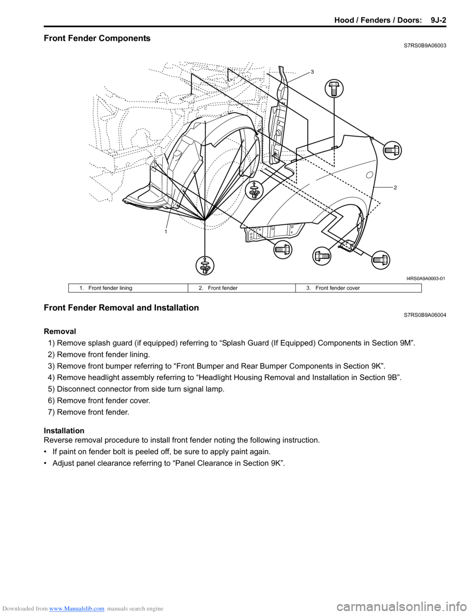
Front Fender ComponentsS7RS0B9A06003
Front Fender Removal and InstallationS7RS0B9A06004
Removal1) Remove splash guard (if equipped) referring to “Splash Guard (If Equipped) Components in Section 9M”.
2) Remove front fender lining.
3) Remove front bumper referring to “Front Bumper and Rear Bumper Components in Section 9K”.
4) Remove headlight assembly referring to “Headlig ht Housing Removal and Installation in Section 9B”.
5) Disconnect connector from side turn signal lamp.
6) Remove front fender cover.
7) Remove front fender.
Installation
Reverse removal procedure to install fron t fender noting the following instruction.
• If paint on fender bolt is peeled off, be sure to apply paint again.
• Adjust panel clearance referring to “Panel Clearance in Section 9K”.
1 2
3
I4RS0A9A0003-01
1. Front fender lining
2. Front fender3. Front fender cover
Page 1399 of 1496

Downloaded from www.Manualslib.com manuals search engine Exterior Trim: 9M-2
Splash Guard (If Equipped) ComponentsS7RS0B9D06002
“A”
“B”
“C”1
I6RS0C9D0002-02
1. Side sill splash guard