Trigger SUZUKI SWIFT 2007 2.G Service Workshop Manual
[x] Cancel search | Manufacturer: SUZUKI, Model Year: 2007, Model line: SWIFT, Model: SUZUKI SWIFT 2007 2.GPages: 1496, PDF Size: 34.44 MB
Page 396 of 1496

Downloaded from www.Manualslib.com manuals search engine 1H-4 Ignition System:
Diagnostic Information and Procedures
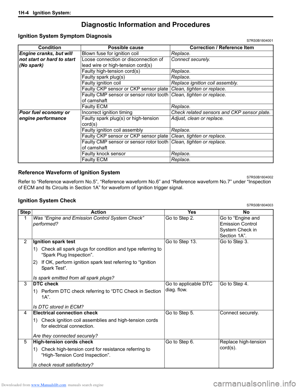
Ignition System Symptom DiagnosisS7RS0B1804001
Reference Waveform of Ignition SystemS7RS0B1804002
Refer to “Reference waveform No.5”, “Reference waveform No.6” and “Reference waveform No.7” under “Inspection
of ECM and Its Circuits in Section 1A” for waveform of Ignition trigger signal.
Ignition System CheckS7RS0B1804003
Condition Possible cause Correction / Reference Item
Engine cranks, but will
not start or hard to start
(No spark) Blown fuse for ignition coil
Replace.
Loose connection or disconnection of
lead wire or high-tension cord(s) Connect securely.
Faulty high-tension cord(s) Replace.
Faulty spark plug(s) Replace.
Faulty ignition coil Replace ignition coil assembly.
Faulty CKP sensor or CKP sensor plate Clean, tighten or replace.
Faulty CMP sensor or sensor rotor tooth
of camshaft Clean, tighten or replace.
Faulty ECM Replace.
Poor fuel economy or
engine performance Incorrect ignition timing
Check related sensors and CKP sensor plate.
Faulty spark plug(s) or high-tension
cord(s) Adjust, clean or replace.
Faulty ignition coil assembly Replace.
Faulty CKP sensor or CKP sensor plate Clean, tighten or replace.
Faulty CMP sensor or sensor rotor tooth
of camshaft Clean, tighten or replace.
Faulty knock sensor Replace.
Faulty ECM Replace.
StepAction YesNo
1 Was “Engine and Emission Control System Check”
performed? Go to Step 2.
Go to “Engine and
Emission Control
System Check in
Section 1A”.
2 Ignition spark test
1) Check all spark plugs for condition and type referring to
“Spark Plug Inspection”.
2) If OK, perform ignition spark test referring to “Ignition Spar k Tes t”.
Is spark emitted from all spark plugs? Go to Step 13. Go to Step 3.
3 DTC check
1) Perform DTC check referring to “DTC Check in Section
1A”.
Is DTC stored in ECM? Go to applicable DTC
diag. flow.
Go to Step 4.
4 Electrical connection check
1) Check ignition coil assemblies and high-tension cords
for electrical connection.
Are they connected securely? Go to Step 5.
Connect securely.
5 High-tension cords check
1) Check high-tension cord for resistance referring to
“High-Tension Cord Inspection”.
Is check result satisfactory? Go to Step 6.
Replace high-tension
cord(s).
Page 397 of 1496

Downloaded from www.Manualslib.com manuals search engine Ignition System: 1H-5
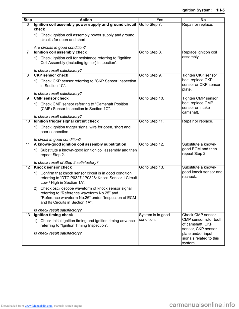
6Ignition coil assembly power supply and ground circuit
check
1) Check ignition coil assembly power supply and ground
circuits for open and short.
Are circuits in good condition? Go to Step 7.
Repair or replace.
7 Ignition coil assembly check
1) Check ignition coil for resistance referring to “Ignition
Coil Assembly (Including ignitor) Inspection”.
Is check result satisfactory? Go to Step 8.
Replace ignition coil
assembly.
8 CKP sensor check
1) Check CKP sensor referring to “CKP Sensor Inspection
in Section 1C”.
Is check result satisfactory? Go to Step 9.
Tighten CKP sensor
bolt, replace CKP
sensor or CKP sensor
plate.
9 CMP sensor check
1) Check CMP sensor referring to “Camshaft Position
(CMP) Sensor Inspection in Section 1C”.
Is check result satisfactory? Go to Step 10. Tighten CMP sensor
bolt, replace CMP
sensor or intake
camshaft.
10 Ignition trigger signal circuit check
1) Check ignition trigger signal wire for open, short and
poor connection.
Is circuit in good condition? Go to Step 11. Repair or replace.
11 A known-good ignition coil assembly substitution
1) Substitute a known-good ignition coil assembly and then
repeat Step 2.
Is check result of Step 2 satisfactory? Go to Step 12. Substitute a known-
good ECM and then
repeat Step 2.
12 Knock sensor check
1) Confirm that knock sensor circuit is in good condition
referring to “DTC P0327 / P0328: Knock Sensor 1 Circuit
Low / High in Section 1A”.
2) Check oscilloscope waveform of knock sensor signal
referring to “Reference waveform No.25” and
“Reference waveform No.26” under “Inspection of ECM
and Its Circuits in Section 1A”.
Is check result satisfactory? Go to Step 13. Substitute a known-
good knock sensor and
recheck.
13 Ignition timing check
1) Check initial ignition timing and ignition timing advance
referring to “Ignition Timing Inspection”.
Is check result satisfactory? System is in good
condition.
Check CMP sensor,
CMP sensor rotor tooth
of camshaft, CKP
sensor, CKP sensor
plate and/or input
signals related to this
system.
Step
Action YesNo