cat SUZUKI SWIFT 2007 2.G Service Workshop Manual
[x] Cancel search | Manufacturer: SUZUKI, Model Year: 2007, Model line: SWIFT, Model: SUZUKI SWIFT 2007 2.GPages: 1496, PDF Size: 34.44 MB
Page 1 of 1496
Downloaded from www.Manualslib.com manuals search engine Suzuki Swift Sport (RS416)
2004-2008 Service/Repair Manual
This Service Manual has been prepared with the latest service information available at the time
of publication. It is subdivided into various group categories and each section contains diagnostic,
disassembly, repair and installation procedures along with complete specifications and tightening
references. Please read this manual carefully before proceeding, as incorrect service procedures
may result in injury or death to service personnel or to the operator’s of the vehicle.
Page 2 of 1496
Downloaded from www.Manualslib.com manuals search engine IMPORTANT
WARNING/CAUTION/NOTE
Please read this manual and follow its instructions carefully. To emphasize special information, the words , and NOTE have special meanings. Pay specia l attention to the messages high-
lighted by these signal words.
The circle with a slash in this manual me ans “Don’t do this” or “Don’t let this happen”.
WARNING!CAUTION!
Indicates a potential hazard that could result in death or injury.
WARNING!
Indicates a potential hazard that could result in vehicle damage.
CAUTION!
NOTE:
Indicates special information to make main tenance easier or instructions clearer.
This service manual is intended for authorized Su zuki dealers and qualified service technicians only.
Inexperienced technicians or technicians without the proper tools and equipment may not be able to
properly perform the services described in this manual.
Improper repair may result in injury to the technician and may render the vehicle unsafe for the driver
and passengers.
WARNING!
For vehicles equipped with a Supplemental Restraint (Air Bag) System:
• Service on and around the air bag system components or wiring must be performed only by an authorized SUZUKI dealer. Refer to “Air Bag System Components and Wiring Location View” under
“General Description” in air bag system section in order to confirm whether you are performing ser-
vice on or near the air bag system components or wiring. Please observe all WARNINGS and “Ser-
vice Precautions” under “On-Vehicl e Service” in air bag system section before performing service
on or around the air bag system components or wiring. Failure to follow WARNINGS could result in
unintentional activation of the system or could re nder the system inoperative. Either of these two
conditions may result in severe injury.
If the air bag system and another vehicle system both need repair, Suzuki recommends that the air
bag system be repaired first, to help av oid unintended air bag system activation.
Do not modify the steering wheel, instrument pa nel or any other air bag system component on or
around air bag system components or wiring. Modi fications can adversely affect air bag system
performance and lead to injury.
If the vehicle will be exposed to temperatures over 93 °C (200 °F), for example, during a paint baking
process, remove the air bag system components, th at is air bag (inflator) modules, SDM and/or seat
belt with pretensioner, beforehand to avoid component damage or unintended activation.
WARNING!
Page 3 of 1496
Downloaded from www.Manualslib.com manuals search engine FOREWORD
This manual (Volumes 1 and 2) contains procedures for diagnosis, maintenance, adjustments, minor service
operations, replacement of components (Service) and for disassembly and reassembly of major components
(Unit Repair-Overhaul).
Applicable Model:
SWIFT (RS416) produced at KOSAI plant in Japan wi th the following vehicle identification numbers
(VINs).
JSAEZC31S############
The contents are classified into sectio ns each of which is given a section number as indicated in the Table of
Contents on following page. And on the first page of ea ch individual section is an index of that section.
This manual should be kept in a handy place for ready reference of the service work.
Strict observance of the so specif ied items will enable one to obtain the full performance of the vehicle.
When replacing parts or servicing by disassembling, it is recommended to use SUZUKI genuine parts, tools and
service materials as specif ied in each description.
All information, illustrations and specif ications contained in this literature are based on the late st product infor-
mation available at the time of publication approval. And used as the main subject of description is the vehicle of
standard specificatio ns among others.
Therefore, note that illustrations may differ from the vehicle being actually serviced.
The right is reserved to make changes at any time without notice.
JSAEZC31S########
Page 4 of 1496
Downloaded from www.Manualslib.com manuals search engine 00
0
1
2
3
4
5
6
7
8
9
10
11
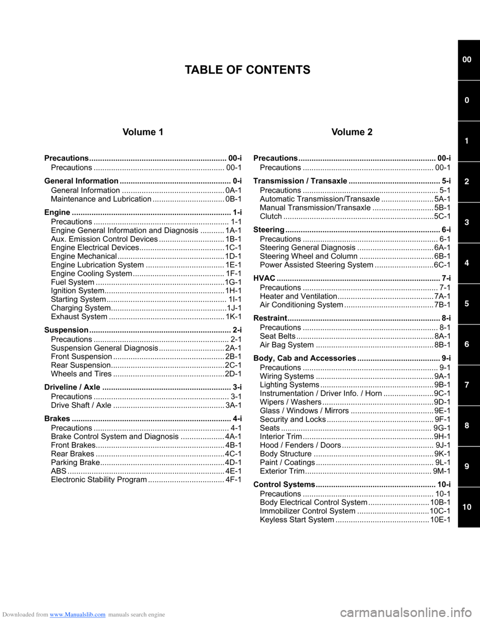
Vo l u m e 1
Precautions............................................................... 00-iPrecautions ............................................................ 00-1
General Information ................ ................................... 0-i
General Information ............................................... 0A-1
Maintenance and Lubricatio n ................................. 0B-1
Engine ......................................................................... 1-i Precautions .............................................................. 1-1
Engine General Information and Diagnosis ........... 1A-1
Aux. Emission Control Devices .............................. 1B-1
Engine Electrical Devices....................................... 1C-1
Engine Mechanical ................................................. 1D-1
Engine Lubrication System .................................... 1E-1
Engine Cooling System .......................................... 1F-1
Fuel System ...........................................................1G-1
Ignition System....................................................... 1H-1
Starting System ....................................................... 1I-1
Charging System.....................................................1J-1
Exhaust System ..................................................... 1K-1
Suspension ................................................................. 2-i Precautions .............................................................. 2-1
Suspension General Diagnosis .............................. 2A-1
Front Suspension ................................................... 2B-1
Rear Suspension................ .................................... 2C-1
Wheels and Tires ................................................... 2D-1
Driveline / Axle ........................................................... 3-i Precautions .............................................................. 3-1
Drive Shaft / Axle ................................................... 3A-1
Brakes ......................................................................... 4-i Precautions .............................................................. 4-1
Brake Control System and Diagnosis .................... 4A-1
Front Brakes........................................................... 4B-1
Rear Brakes ........................................................... 4C-1
Parking Brake......................................................... 4D-1
ABS ........................................................................ 4E-1
Electronic Stability Program ................................... 4F-1
Vo l u m e 2
Precautions ............................................................... 00-iPrecautions ............................................................ 00-1
Transmission / Transaxle .... ...................................... 5-i
Precautions .............................................................. 5-1
Automatic Transmission/Transaxle ........................ 5A-1
Manual Transmission/Transaxle ............................ 5B-1
Clutch .....................................................................5C-1
Steering ....................................................................... 6-i Precautions .............................................................. 6-1
Steering General Diagnosis ................................... 6A-1
Steering Wheel and Column .................................. 6B-1
Power Assisted Steering System ...........................6C-1
HVAC ........................................................................... 7-i Precautions .............................................................. 7-1
Heater and Ventilation............................................ 7A-1
Air Conditioning System ......................................... 7B-1
Restraint ...................................................................... 8-i Precautions .............................................................. 8-1
Seat Belts ............................................................... 8A-1
Air Bag System ...................................................... 8B-1
Body, Cab and Accessories .... .................................. 9-i
Precautions .............................................................. 9-1
Wiring Systems ...................................................... 9A-1
Lighting Systems .................................................... 9B-1
Instrumentation / Driver Info. / Horn .......................9C-1
Wipers / Washers ...................................................9D-1
Glass / Windows / Mirrors ...................................... 9E-1
Security and Locks ................................................. 9F-1
Seats ..................................................................... 9G-1
Interior Trim ............................................................9H-1
Hood / Fenders / Doors .......................................... 9J-1
Body Structure ....................................................... 9K-1
Paint / Coatings ...................................................... 9L-1
Exterior Trim .......................................................... 9M-1
Control Systems ....................................................... 10-i Precautions ............................................................ 10-1
Body Electrical Control Sy stem ............................ 10B-1
Immobilizer Control System .................................10C-1
Keyless Start System ........................................... 10E-1
TABLE OF CONTENTS
Page 5 of 1496
Downloaded from www.Manualslib.com manuals search engine Table of Contents 00- i
00
Section 00
CONTENTS
Precautions
Precautions ............................................... 00-1
Precautions........................................................... 00-1
Precautions for Vehicles Equipped with a Supplemental Restraint (A ir Bag) System ........ 00-1
General Precautions ........... ................................ 00-4
Warning for Wheel (with tire) Removal ............... 00-7
Warning for Handling Emergency Flat Tire Repair Kit .......................................................... 00-7
Precautions for Catalytic Converter .................... 00-7
Precautions for Installing Mobile Communication Equipment ............................... 00-7
Precaution for CAN Communication System ...... 00-7 Precautions for Electrical Circuit Service ............ 00-8
Air Bag Warning ................................................ 00-10
Air Bag System Service Warning ...................... 00-10
Fastener Caution............................................... 00-10
Suspension Caution .......................................... 00-10
Wheels and Tires Caution ................................. 00-10
Precaution for Vehicle Equipped with ESP
®
System ............................................................ 00-11
Brake Caution ................................................... 00-11
Repair Instructions ........ .................................... 00-11
Electrical Circuit Inspection Procedure ............. 00-11
Intermittent and Poor Co nnection Inspection .... 00-13
Page 6 of 1496
Downloaded from www.Manualslib.com manuals search engine 00-1 Precautions:
Precautions
Precautions
Precautions
Precautions for Vehicles Equipped with a
Supplemental Restraint (Air Bag) System
S7RS0B0000001
WARNING!
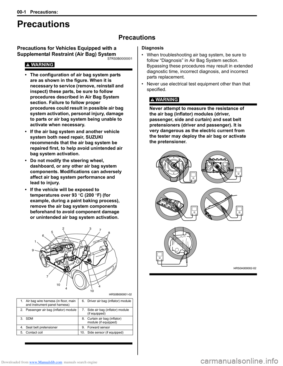
• The configuration of air bag system parts are as shown in the figure. When it is
necessary to service (remove, reinstall and
inspect) these parts, be sure to follow
procedures described in Air Bag System
section. Failure to follow proper
procedures could result in possible air bag
system activation, personal injury, damage
to parts or air bag system being unable to
activate when necessary.
• If the air bag system and another vehicle system both need repair, SUZUKI
recommends that the air bag system be
repaired first, to help avoid unintended air
bag system activation.
• Do not modify the steering wheel, dashboard, or any other air bag system
components. Modifications can adversely
affect air bag system performance and
lead to injury.
• If the vehicle will be exposed to temperatures over 93 °C (200 °F) (for
example, during a paint baking process),
remove the air bag system components
beforehand to avoid component damage
or unintended air bag system activation.
Diagnosis
• When troubleshooting air bag system, be sure to follow “Diagnosis” in Air Bag System section.
Bypassing these procedures may result in extended
diagnostic time, incorrect diagnosis, and incorrect
parts replacement.
• Never use electrical test equipment other than that specified.
WARNING!
Never attempt to measure the resistance of
the air bag (inflator) modules (driver,
passenger, side and curtain) and seat belt
pretensioners (driver and passenger). It is
very dangerous as the electric current from
the tester may deploy the air bag or activate
the pretensioner.
1. Air bag wire harness (in floor, main and instrument panel harness) 6. Driver air bag (inflator) module
2. Passenger air bag (inflator) module 7. Side air bag (inflator) module (if equipped)
3. SDM 8. Curtain air bag (inflator) module (if equipped)
4. Seat belt pretensioner 9. Forward sensor
5. Contact coil 10. Side sensor (if equipped)
1 2
3
4
4
5
6
7 7
8
9
10 10
I4RS0B000001-02
I4RS0A000002-02
Page 7 of 1496
Downloaded from www.Manualslib.com manuals search engine Precautions: 00-2
Servicing and Handling
WARNING!
Many of service procedures require
disconnection of “A/BAG” fuse and all air
bag (inflator) module(s) from initiator circuit
to avoid an accidental deployment.
Driver, Passenger, Side and Curtain Air Bag
(Inflator) Modules
• For handling and storage of a live air bag (inflator) module, select a place where the
ambient temperature below 65 °C (150 ° F),
without high humidity and away from
electric noise.
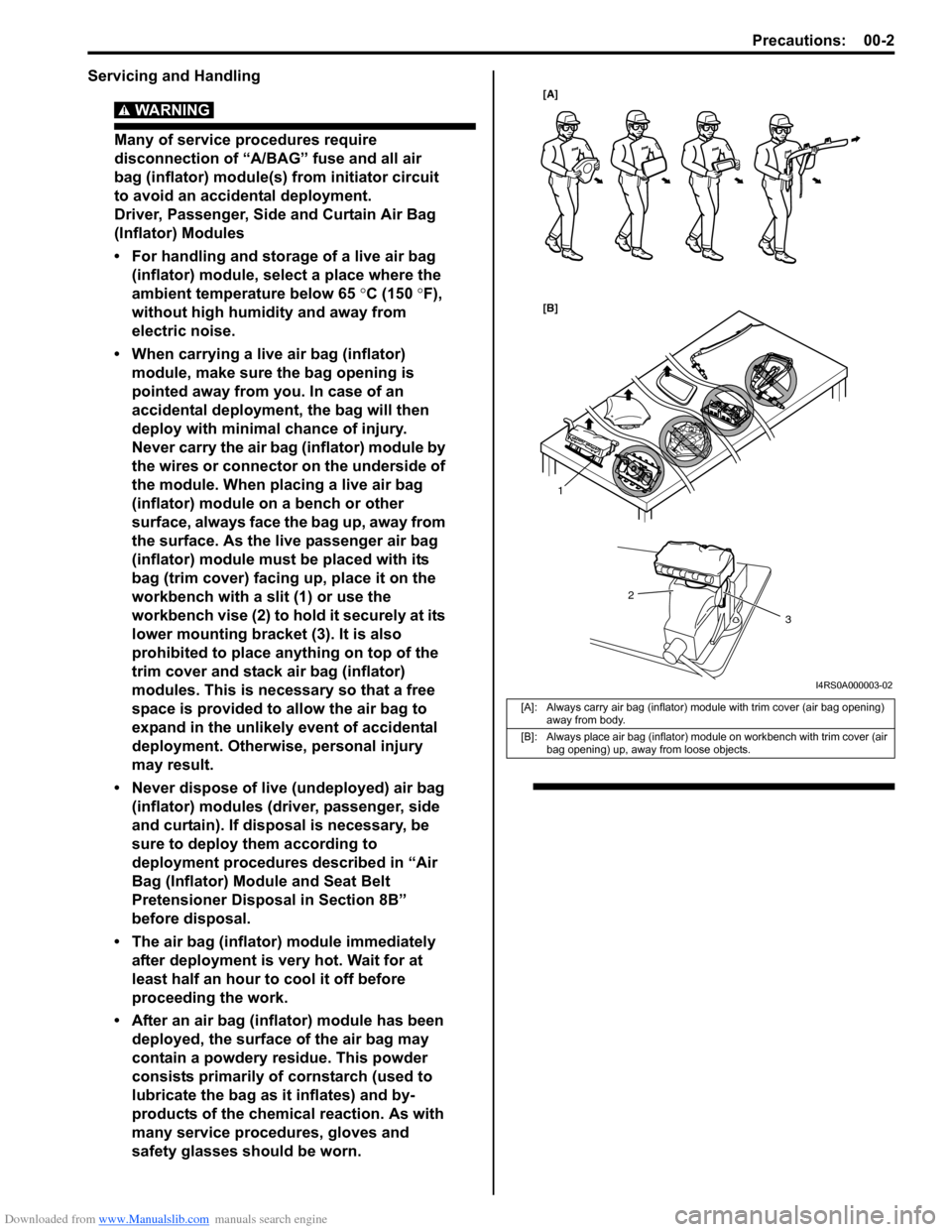
• When carrying a live air bag (inflator) module, make sure the bag opening is
pointed away from you. In case of an
accidental deployment, the bag will then
deploy with minimal chance of injury.
Never carry the air bag (inflator) module by
the wires or connector on the underside of
the module. When placing a live air bag
(inflator) module on a bench or other
surface, always face the bag up, away from
the surface. As the live passenger air bag
(inflator) module must be placed with its
bag (trim cover) facing up, place it on the
workbench with a slit (1) or use the
workbench vise (2) to hold it securely at its
lower mounting bracket (3). It is also
prohibited to place anything on top of the
trim cover and stack air bag (inflator)
modules. This is necessary so that a free
space is provided to allow the air bag to
expand in the unlikely event of accidental
deployment. Otherwise, personal injury
may result.
• Never dispose of live (undeployed) air bag (inflator) modules (driver, passenger, side
and curtain). If disposal is necessary, be
sure to deploy them according to
deployment procedures described in “Air
Bag (Inflator) Module and Seat Belt
Pretensioner Disposal in Section 8B”
before disposal.
• The air bag (inflator) module immediately
after deployment is very hot. Wait for at
least half an hour to cool it off before
proceeding the work.
• After an air bag (inflator) module has been deployed, the surface of the air bag may
contain a powdery residue. This powder
consists primarily of cornstarch (used to
lubricate the bag as it inflates) and by-
products of the chemical reaction. As with
many service procedures, gloves and
safety glasses should be worn.
[A]: Always carry air bag (inflator) module with trim cover (air bag opening) away from body.
[B]: Always place air bag (inflator) module on workbench with trim cover (air bag opening) up, away from loose objects.
1
2
3
[A]
[B]
I4RS0A000003-02
Page 12 of 1496
Downloaded from www.Manualslib.com manuals search engine 00-7 Precautions:
Warning for Wheel (with tire) RemovalS7RS0B0000003
WARNING!
When removing any of these wheels installed
with wheel bolts, never remove all wheel
bolts at the same time. Leave at least 1 bolt
for each wheel as it is to prevent wheel from
dropping. When removing this remaining 1
bolt, hold wheel and tire so as not to allow
them to come off.
Warning for Handling Emergency Flat Tire
Repair Kit
S7RS0B0000004
WARNING!
If vehicle is equipped with Emergency Flat
Tire Repair Kit instead of spare tire, be sure
to observe “Precaution for Emergency Flat
Tire Repair Kit in Section 2D” when handling
Emergency Flat Tire Repair Kit and repairing
flat tire.
Otherwise, your health may be ruined or it
will be impossible to repair flat tire.
Precautions for Catalytic ConverterS7RS0B0000005
For vehicles equipped with a catalytic converter, use
only unleaded gasoline and be careful not to let a large
amount of unburned gasoline enter the converter or it
can be damaged.
• Conduct a spark jump test only when necessary, make it as short as possible, and do not open the
throttle.
• Conduct engine compression checks within the shortest possible time.
• Avoid situations which can result in engine misfire (e.g. starting the engine when the fuel tank is nearly
empty.)
Precautions for Installing Mobile
Communication Equipment
S7RS0B0000006
When installing mobile communication equipment such
as CB (Citizens-Band)-radi o or cellular-telephone, be
sure to observe the following precautions.
Failure to follow cautions may adversely affect electronic
control system.
• Keep the antenna as far away as possible from the vehicle’s electronic control unit.
• Keep the antenna feeder more than 20 cm (7.9 in.) away from electronic control unit and its wire
harnesses.
• Do not run the antenna feeder parallel with other wire harnesses.
• Confirm that the antenna and feeder are correctly adjusted.
Precaution for CAN Communication SystemS7RS0B0000007
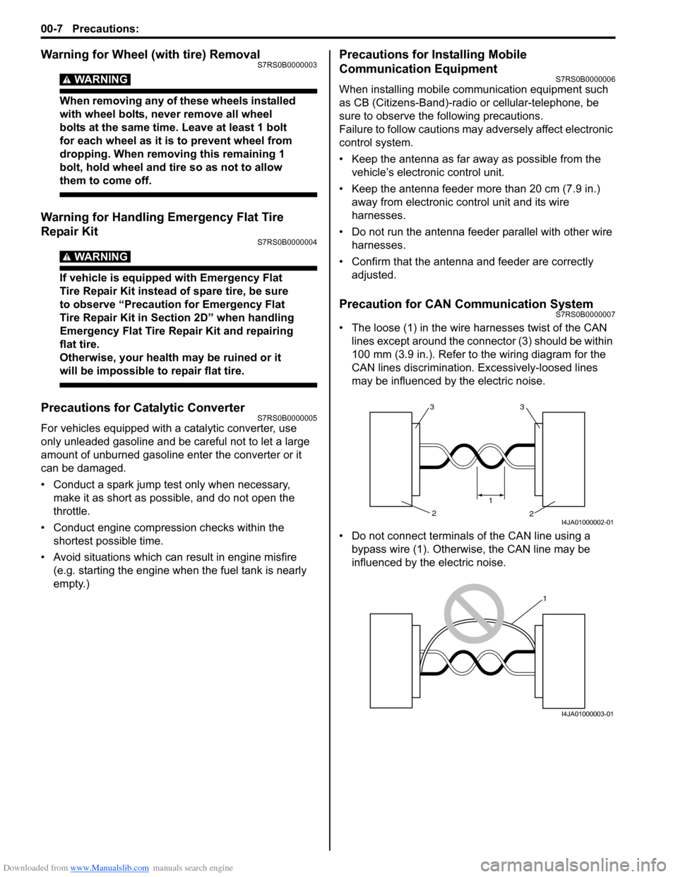
• The loose (1) in the wire harnesses twist of the CAN lines except around the connector (3) should be within
100 mm (3.9 in.). Refer to the wiring diagram for the
CAN lines discrimination. Excessively-loosed lines
may be influenced by the electric noise.
• Do not connect terminals of the CAN line using a bypass wire (1). Otherwise, the CAN line may be
influenced by the electric noise.
33
2
2
1
I4JA01000002-01
1
I4JA01000003-01
Page 15 of 1496
Downloaded from www.Manualslib.com manuals search engine Precautions: 00-10
Air Bag WarningS7RS0B0000009
WARNING!
For vehicles equipped with Supplemental
Restraint (Air Bag) System:
• Service on and around the air bag system components or wiring must be performed
only by an authorized SUZUKI dealer. Refer
to “Air Bag System Components, Wiring
and Connectors Location in Section 8B” in
order to confirm whether you are
performing service on or near the air bag
system components or wiring. Please
observe all WARNINGS in Air Bag System
section and “Precautions on Service and
Diagnosis of Air Bag System in Section
8B” before performing service on or
around the air bag system components or
wiring. Failure to follow WARNINGS could
result in unintentional activation of the
system or could render the system
inoperative. Either of these two conditions
may result in severe injury.
• Technical service work must be started at least 90 seconds after the ignition switch is
turned to the LOCK position and the
negative cable is disconnected from the
battery. Otherwise, the system may be
activated by reserve energy in the Sensing
and Diagnostic Module (SDM).
Air Bag System Service WarningS7RS0B0000010
WARNING!
• Service on or around the air bag system components or wiring must be performed
only by an authorized SUZUKI dealer.
Please observe all WARNINGS in Air Bag
System section and “Precautions on
Service and Diagnosis of Air Bag System
in Section 8B” before performing service
on or around the air bag system
components or wiring. Failure to follow
WARNINGS could result in unintended
activation of the system or could render
the system inoperative. Either of these two
conditions may result in severe injury.
• The procedures in the air bag system section must be followed in the order
listed to disable the air bag system
temporarily and prevent false DTCs from
setting. Failure to follow procedures could
result in possible activation of the air bag
system, personal injury or otherwise
unneeded air bag system repairs.
Fastener CautionS7RS0B0000011
CAUTION!
When fasteners are removed, always reinstall
them at the same location from which they
were removed. If a fastener needs to be
replaced, use the correct part number
fastener for that application. If the correct
part number fastener is not available, a
fastener of equal size and strength (or
stronger) may be used. Fasteners that are not
reused, and those requiring thread-locking
compound, will be called out. The correct
torque value must be used when installing
fasteners that require it. If the conditions are
not followed, parts or system damage could
result.
Suspension CautionS7RS0B0000012
CAUTION!
• All suspension fasteners are an important attaching part in that it could affect the
performance of vital parts and systems,
and/or could result in major repair
expense. They must be replaced with one
of the same part number or with an
equivalent part if replacement becomes
necessary. Do not use a replacement part
of lesser quality or substitute design.
Torque values must be used as specified
during reassembly to assure proper
retention of this part.
• Never attempt to heat, quench or straighten any suspension part. Replace it
with a new part or damage to the part may
result.
Wheels and Tires CautionS7RS0B0000013
CAUTION!
All wheel fasteners are important attaching
parts in that they could affect the
performance of vital parts and systems, and/
or could result in major repair expense. They
must be replaced with one of the same part
number or with an eq uivalent part if
replacement becomes necessary. Do not use
a replacement part of lesser quality or
substitute design. Torque values must be
used as specified during reassembly to
assure proper retention of all parts.
There is to be no welding as it may result in
extensive damage and weakening of the
metal.
Page 17 of 1496
Downloaded from www.Manualslib.com manuals search engine Precautions: 00-12
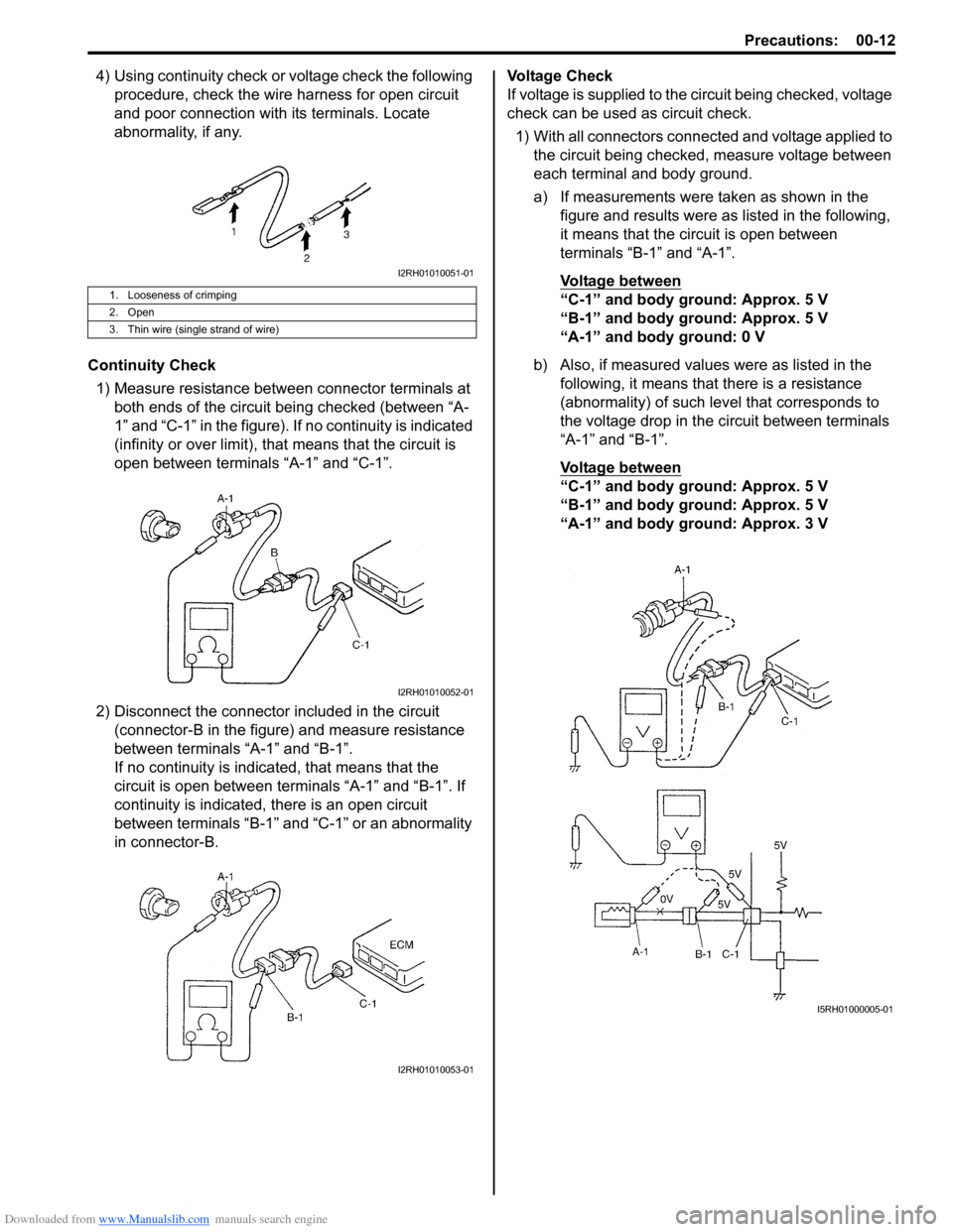
4) Using continuity check or voltage check the following procedure, check the wire harness for open circuit
and poor connection with its terminals. Locate
abnormality, if any.
Continuity Check 1) Measure resistance between connector terminals at both ends of the circuit being checked (between “A-
1” and “C-1” in the figure). If no continuity is indicated
(infinity or over limit), that means that the circuit is
open between terminals “A-1” and “C-1”.
2) Disconnect the connector included in the circuit (connector-B in the figure) and measure resistance
between terminals “A-1” and “B-1”.
If no continuity is indica ted, that means that the
circuit is open between terminals “A-1” and “B-1”. If
continuity is indicated, there is an open circuit
between terminals “B-1” and “C-1” or an abnormality
in connector-B. Voltage Check
If voltage is supplied to the circuit being checked, voltage
check can be used as circuit check.
1) With all connectors connected and voltage applied to the circuit being checked, measure voltage between
each terminal and body ground.
a) If measurements were taken as shown in the figure and results were as listed in the following,
it means that the circuit is open between
terminals “B-1” and “A-1”.
Voltage between
“C-1” and body ground: Approx. 5 V
“B-1” and body ground: Approx. 5 V
“A-1” and body ground: 0 V
b) Also, if measured values were as listed in the following, it means that there is a resistance
(abnormality) of such le vel that corresponds to
the voltage drop in the circuit between terminals
“A-1” and “B-1”.
Voltage between
“C-1” and body ground: Approx. 5 V
“B-1” and body ground: Approx. 5 V
“A-1” and body ground: Approx. 3 V
1. Looseness of crimping
2. Open
3. Thin wire (single strand of wire)
I2RH01010051-01
I2RH01010052-01
I2RH01010053-01
I5RH01000005-01