clock display removal SUZUKI SWIFT 2007 2.G Service Workshop Manual
[x] Cancel search | Manufacturer: SUZUKI, Model Year: 2007, Model line: SWIFT, Model: SUZUKI SWIFT 2007 2.GPages: 1496, PDF Size: 34.44 MB
Page 1011 of 1496

Downloaded from www.Manualslib.com manuals search engine Air Conditioning System: Automatic Type 7B-63
DTC B1546: A/C Refrigerant Pressure MalfunctionS7RS0B7224018
DTC Detecting Condition and Trouble Area
DTC Troubleshooting
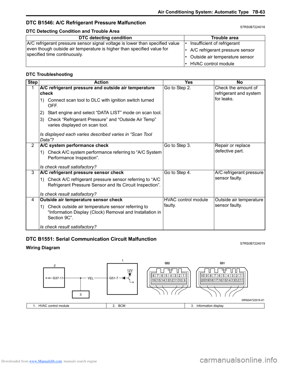
DTC B1551: Serial Communication Circuit MalfunctionS7RS0B7224019
Wiring DiagramDTC detecting condition Trouble area
A/C refrigerant pressure sensor signal voltage is lower t han specified value
even though outside air temperature is higher than specified value for
specified time continuously. • Insufficient of refrigerant
• A/C refrigerant pressure sensor
• Outside air temperature sensor
• HVAC control module
Step
Action YesNo
1 A/C refrigerant pressure and outside air temperature
check
1) Connect scan tool to DLC with ignition switch turned
OFF.
2) Start engine and select “DATA LIST” mode on scan tool.
3) Check “Refrigerant Pressure” and “Outside Air Temp” varies displayed on scan tool.
Is displayed each va ries described varies in “Scan Tool
Data”? Go to Step 2.
Check the amount of
refrigerant and system
for leaks.
2 A/C system performance check
1) Check A/C system performance referring to “A/C System
Performance Inspection”.
Is check result satisfactory? Go to Step 3.
Repair or replace
defective part.
3 A/C refrigerant pressure sensor check
1) Check A/C refrigerant pressure sensor referring to “A/C
Refrigerant Pressure Sensor and Its Circuit Inspection”.
Is check result satisfactory? Go to Step 4.
A/C refrigerant pressure
sensor faulty.
4 Outside air temperature sensor check
1) Check outside air temperature sensor referring to
“Information Display (Clock) Removal and Installation in
Section 9C”.
Is check result satisfactory? HVAC control module
faulty.
Outside air temperature
sensor faulty.
YEL17812910
65 431516 14 13 12 11
G52
789101920121112
65 431718 16 15 14 13
G51
G51-7
12V
2
3
G37-11
I5RS0A722016-01
1. HVAC control module 2. BCM3. Information display
Page 1025 of 1496

Downloaded from www.Manualslib.com manuals search engine Air Conditioning System: Automatic Type 7B-77
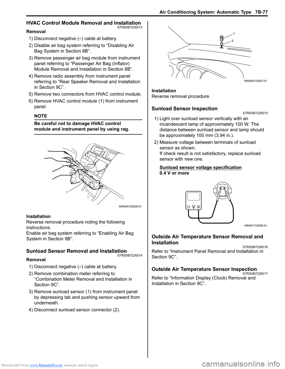
HVAC Control Module Removal and InstallationS7RS0B7226013
Removal1) Disconnect negative (–) cable at battery.
2) Disable air bag system referring to “Disabling Air Bag System in Section 8B”.
3) Remove passenger air bag module from instrument panel referring to “Passenger Air Bag (Inflator)
Module Removal and Installation in Section 8B”.
4) Remove radio assembly from instrument panel referring to “Rear Speaker Removal and Installation
in Section 9C”.
5) Remove two connectors fr om HVAC control module.
6) Remove HVAC control modu le (1) from instrument
panel.
NOTE
Be careful not to damage HVAC control
module and instrument panel by using rag.
Installation
Reverse removal procedure noting the following
instructions.
Enable air bag system referring to “Enabling Air Bag
System in Section 8B”.
Sunload Sensor Removal and InstallationS7RS0B7226014
Removal
1) Disconnect negative (–) cable at battery.
2) Remove combination meter referring to “Combination Meter Removal and Installation in
Section 9C”.
3) Remove sunload sensor (1) from instrument panel by depressing tab and pushing sensor upward from
underneath.
4) Disconnect sunload sensor connector (2). Installation
Reverse removal procedure.
Sunload Sensor InspectionS7RS0B7226015
1) Light over sunload sensor vertically with an
incandescent lamp of approximately 100 W. The
distance between sunload sensor and lamp should
be approximately 100 mm (3.94 in.).
2) Measure voltage between terminals of sunload sensor as shown.
If check result is not satisfactory, replace sunload
sensor with new one.
Sunload sensor voltage specification
0.4 V or more
Outside Air Temperature Sensor Removal and
Installation
S7RS0B7226016
Refer to “Instrument Panel Re moval and Installation in
Section 9C”.
Outside Air Temperature Sensor InspectionS7RS0B7226017
Refer to “Information Display (Clock) Removal and
Installation in Section 9C”.
1
I5RS0A722030-01
1
2
I5RS0A722027-01
I4RH01722036-01
Page 1168 of 1496

Downloaded from www.Manualslib.com manuals search engine 9-ii Table of Contents
List of Connectors ........................................... 9A-103
C Connector .................................................... 9A-103
D Connector (M16A engine) ........................... 9A-104
E Connector .................................................... 9A-104
G Connector .................................................... 9A-106
J Connector ..................................................... 9A-108
K Connector .................................................... 9A-109
L Connector..................................................... 9A-109
M Connector (SPORT model) ......................... 9A-111
O Connector .................................................... 9A-111
R Connector .................................................... 9A-111
Lighting Systems .................................... 9B-1
Component Location ........... ................................9B-1
Lighting System Component s Location............... 9B-1
Interior Light System Location............................. 9B-2
Diagnostic Information and Procedures ............ 9B-2 Headlight Symptom Diagnosis ............................ 9B-2
Headlight Leveling System Symptom Diagnosis (If Equipped) ..................................... 9B-2
Turn Signal and Hazard Warning Light Symptom Diagnosis .......................................... 9B-3
Clearance, Tail and License Plate Light Symptom Diagnosis .......................................... 9B-3
Back-Up Light Symptom Diagnosis..................... 9B-4
Brake Light Symptom Diagnosis ......................... 9B-4
Front Fog Light Symptom Diagnosis (If Equipped) .......................................................... 9B-4
Interior Light Symptom Diagnosis ....................... 9B-5
Repair Instructions ..............................................9B-5 Headlight Housing Removal and Installation ...... 9B-5
Headlight Bulb Replacemen t............................... 9B-6
Headlight Aiming Adjustment with Screen .......... 9B-6
Headlight Switch (in Lighting Switch) Removal and Installation ................................... 9B-8
Headlight Switch (in Lighting Switch) Inspection .......................................................... 9B-8
Hazard Warning Switch Removal and Installation ......................................................... 9B-8
Hazard Warning Switch Inspection ..................... 9B-9
Brake Light Switch Inspection ............................. 9B-9
Turn Signal Light Switch (in Lighting Switch) Removal and Installation ................................... 9B-9
Turn Signal Light Switch (in Lighting Switch) Inspection .......................................................... 9B-9
Turn Signal and Hazard Warning Relay Removal and Installation ................................... 9B-9
Turn Signal and Hazard Warning Relay Inspection ........................................................ 9B-10
License Light Removal and Installation............. 9B-10
Front Fog Light Removal and Installation (If Equipped) ........................................................ 9B-11
Front Fog Light Bulb Replacement (If Equipped) ........................................................ 9B-11
Front Fog Light Switch Inspection (If Equipped) ........................................................ 9B-11
Front Fog Light Relay Inspection (If Equipped) ........................................................ 9B-11
Front Fog Light Aiming Adjustment with Screen (If Equipped) ....................................... 9B-12 Headlight Leveling Switch Inspection (If
Equipped) ........................................................ 9B-13
Headlight Leveling Actuator Inspection (If Equipped) ........................................................ 9B-13
Instrumentation / Driver Info. / Horn ...... 9C-1
Precautions ...........................................................9C-1 Precautions in Diagnosing Troubles for Combination Meter ............................................9C-1
General Description .............................................9C-1 CAN Communication System Description...........9C-1
Auto Volume Co ntrol System Description (If
Equipped) ..........................................................9C-3
Schematic and Routing Diagram ........................9C-4 Combination Meter Circuit Diagram ....................9C-4
Component Location ............ ...............................9C-6
Audio System Component Location ....................9C-6
Diagnostic Information and Procedures ............9C-6 Speedometer and VSS Symp tom Diagnosis ......9C-6
Tachometer Symptom Diagnosis ........................9C-6
Engine Coolant Temperature (ECT) Meter Symptom Diagnosis ..........................................9C-7
Fuel Meter Symptom Diagnosis ..........................9C-7
Low Fuel Warning Light Symptom Diagnosis .....9C-7
Oil Pressure Warning Light Symptom Diagnosis ..........................................................9C-8
Brake and Parking Brake Warning Light Symptom Diagnosis ..........................................9C-8
Seat Belt Reminder Light Symptom Diagnosis (If Equipped)......................................................9C-8
A/T Shift Position Indicator Symptom Diagnosis (A/T Model).......................................9C-9
Charge Warning Light Sy mptom Diagnosis ........9C-9
Main Beam (High Beam) Indicator Symptom Diagnosis ..........................................................9C-9
Warning Buzzer Circuit Sy mptom Diagnosis ....9C-10
Cigarette Lighter Symptom Diagnosis (If Equipped) ........................................................9C-10
Horn Symptom Diagnosis .................................9C-10
Information Display Symptom Diagnosis (If Equipped) ........................................................9C-11
Clock Symptom Diagnosis (If Equipped)...........9C-12
Audio System Symptom Diagnosis (If Equipped) ........................................................9C-12
Remote Audio Control Switch Symptom Diagnosis (If Equipped) ...................................9C-13
Navigation Symptom Diagnosis (If Equipped)...9C-14
Repair Instructions ............ ................................9C-14
Ignition Switch Removal and Installation...........9C-14
Ignition Switch Inspection..................................9C-14
Combination Meter Removal and Installation ...9C-15
Fuel Level Sensor Removal and Installation .....9C-15
Fuel Level Sensor Inspection ............................9C-15
Oil Pressure Switch Remova l and Installation ..9C-15
Oil Pressure Switch Inspec tion .........................9C-16
Engine Coolant Temperature (ECT) Sensor Inspection ........................................................9C-16
Brake Fluid Level Switch Inspection .................9C-16
Parking Brake Switch Inspec tion.......................9C-16
Page 1169 of 1496

Downloaded from www.Manualslib.com manuals search engine Table of Contents 9-iii
Door Switch (Front / Rear Door) Inspection ...... 9C-17
Rear End Door Switch Inspection ..................... 9C-17
Outside Air Temperature Sensor Removal and Installation (If Equipped) .......................... 9C-17
Outside Air Temperature Sensor Inspection (If Equipped) ................................................... 9C-17
Instrument Panel Removal and Installation....... 9C-18
Information Display (Clock) Removal and Installation ....................................................... 9C-19
Audio Unit Removal and In stallation ................. 9C-19
Front Speaker Removal and Installation ........... 9C-19
Rear Speaker Removal and Installation............ 9C-20
Horn Removal and Installation .......................... 9C-20
Horn Inspection ................................................. 9C-20
Horn Relay Inspection ....................................... 9C-20
Antenna Amplifier Removal and Installation ..... 9C-21
Remote Audio Control Switch Removal and Installation (If Equipped) ................................. 9C-21
Remote Audio Control Switch Inspection (If Equipped)........................................................ 9C-22
Vehicle Speed Signal Inspection (For Audio Unit) (If Equipped) ........................................... 9C-22
Specifications ..................................................... 9C-22
Tightening Torque Specifications ...................... 9C-22
Wipers / Washers............ ......................... 9D-1
Diagnostic Information and Procedures ............ 9D-1
Front Wiper and Washer Symptom Diagnosis .... 9D-1
Rear Wiper and Washer Symptom Diagnosis..... 9D-1
Repair Instructions .............................................. 9D-2 Wipers and Washers Components ..................... 9D-2
Washer Tank and Washer Pump Removal and Installation .................................................. 9D-3
Washer Pump Inspection .................................... 9D-3
Windshield Wiper Removal and Installation ........ 9D-4
Windshield Wiper Motor Inspection..................... 9D-5
Rear Wiper Removal and Installation.................. 9D-6
Rear Wiper Motor Inspection .............................. 9D-7
Windshield Wiper and Washer Switch Removal and Installation................................... 9D-7
Windshield Wiper and Washer Switch Inspection.......................................................... 9D-8
Rear Wiper and Washer Switch Removal and Installation ......................................................... 9D-9
Rear Wiper and Washer Switch Inspection......... 9D-9
Rear Wiper Relay Removal and Installation ..... 9D-10
Rear Wiper Relay Inspection ............................ 9D-10
Specifications ..................................................... 9D-10
Tightening Torque Specifications ...................... 9D-10
Glass / Windows / Mirrors.. ..................... 9E-1
General Description ............................................. 9E-1
Rear End Door Window Defogger System Description ........................................................ 9E-1
Windshield Construction ..................................... 9E-1
Diagnostic Information and Procedures ............ 9E-2 Rear End door Window Defogger Symptom Diagnosis .......................................................... 9E-2 Power Window Control System Symptom
Diagnosis .......................................................... 9E-2
Power Door Mirror Control System Symptom Diagnosis .......................................................... 9E-3
Door Mirror Heater Symptom Diagnosis (If
Equipped) .......................................................... 9E-3
Repair Instructions ........... ................................... 9E-4
Windshield Removal and In stallation .................. 9E-4
Front Door Window Components ........................ 9E-8
Front Door Glass Removal and Installation ........ 9E-8
Front Door Window Re gulator Removal and
Installation ......................................................... 9E-9
Front Door Window Regula tor Inspection ......... 9E-10
Rear Door Window Components ...................... 9E-10
Rear Door Glass Removal and Installation ....... 9E-11
Rear Door Window Regulator Removal and Installation ....................................................... 9E-12
Rear Door Window Regulato r Inspection .......... 9E-12
Rear End Door Window Components ............... 9E-13
Rear End Door Glass Removal and Installation ....................................................... 9E-13
Rear End Door Window Defogger Switch Inspection ........................................................ 9E-14
Rear End Door Window Defogger Relay Inspection ........................................................ 9E-14
Rear End Door Window Defogger Wire Inspection ........................................................ 9E-15
Rear End Door Window Defogger Wire
Repair.............................................................. 9E-15
Power Window Main Switch Inspection ............ 9E-16
Power Window Sub Switch Inspection .............. 9E-17
Door Mirror Components.. ................................. 9E-18
Door Mirror Removal and In stallation................ 9E-18
Power Door Mirror Switch Inspection ................ 9E-18
Power Door Mirror Actuator Inspection ............. 9E-19
Door Mirror Heater Switch Inspection (If Equipped) ........................................................ 9E-19
Door Mirror Heater Inspec tion (If Equipped) ..... 9E-19
Special Tools and Equipmen t ........................... 9E-19
Recommended Service Material ....................... 9E-19
Security and Locks......... ..........................9F-1
General Description ............................................. 9F-1
Key Coding Construction .................................... 9F-1
Rear End Door Opener System Description ....... 9F-1
Component Location ............ ............................... 9F-2
Power Door Lock and Keyless Entry System
Component Location ......................................... 9F-2
Diagnostic Information and Procedures ............ 9F-3 Power Door Lock System Symptom Diagnosis .......................................................... 9F-3
Power Door Lock System Operation Inspection .......................................................... 9F-3
Keyless Entry System Symptom Diagnosis (If
Equipped) .......................................................... 9F-4
Keyless Entry System Operation Inspection ....... 9F-5
Door Lock Function of Keyless Start System Symptom Diagnosis (If Equipped)..................... 9F-5
Page 1314 of 1496

Downloaded from www.Manualslib.com manuals search engine 9C-19 Instrumentation / Driver Info. / Horn:
Installation
Reverse removal procedure noting the following.
• When installing each part, be careful not to catch any
cable or wiring harness.
• Tighten instrument panel mounting bolts to specified
torque
Tightening torque
Instrument panel mounting bolt (a): 23 N·m (2.3
kgf-m, 17.0 lb-ft)
• Tighten steering column mounting nuts referring to “Steering Column Removal an d Installation in Section
6B”.
• Enable air bag system referring to “Enabling Air Bag System in Section 8B”.
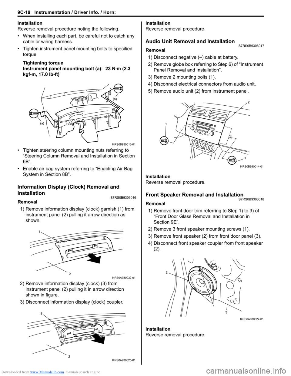
Information Display (Clock) Removal and
Installation
S7RS0B9306016
Removal
1) Remove information display (clock) garnish (1) from instrument panel (2) pulling it arrow direction as
shown.
2) Remove information di splay (clock) (3) from
instrument panel (2) pulli ng it in arrow direction
shown in figure.
3) Disconnect information display (clock) coupler. Installation
Reverse removal procedure.
Audio Unit Removal and InstallationS7RS0B9306017
Removal
1) Disconnect negative (–) cable at battery.
2) Remove globe box referring to Step 6) of “Instrument Panel Removal and Installation”.
3) Remove 2 mounting bolts (1).
4) Disconnect electrical connectors from audio unit.
5) Remove audio unit (2) from instrument panel.
Installation
Reverse removal procedure.
Front Speaker Removal and InstallationS7RS0B9306018
Removal 1) Remove front door trim refe rring to Step 1) to 3) of
“Front Door Glass Remo val and Installation in
Section 9E”.
2) Remove 3 front speaker mounting screws (1).
3) Remove front speaker (2) from front door panel (3).
4) Disconnect front speaker coupler from front speaker (2).
Installation
Reverse removal procedure.
(a) (a)
I4RS0B930013-01
1
2I4RS0A930032-01
3
2I4RS0A930025-01
2
1
1
I4RS0B930014-01
1
2
3
I4RS0A930027-01