cooling system refill SUZUKI SWIFT 2007 2.G Service Workshop Manual
[x] Cancel search | Manufacturer: SUZUKI, Model Year: 2007, Model line: SWIFT, Model: SUZUKI SWIFT 2007 2.GPages: 1496, PDF Size: 34.44 MB
Page 35 of 1496
Downloaded from www.Manualslib.com manuals search engine Maintenance and Lubrication: 0B-5
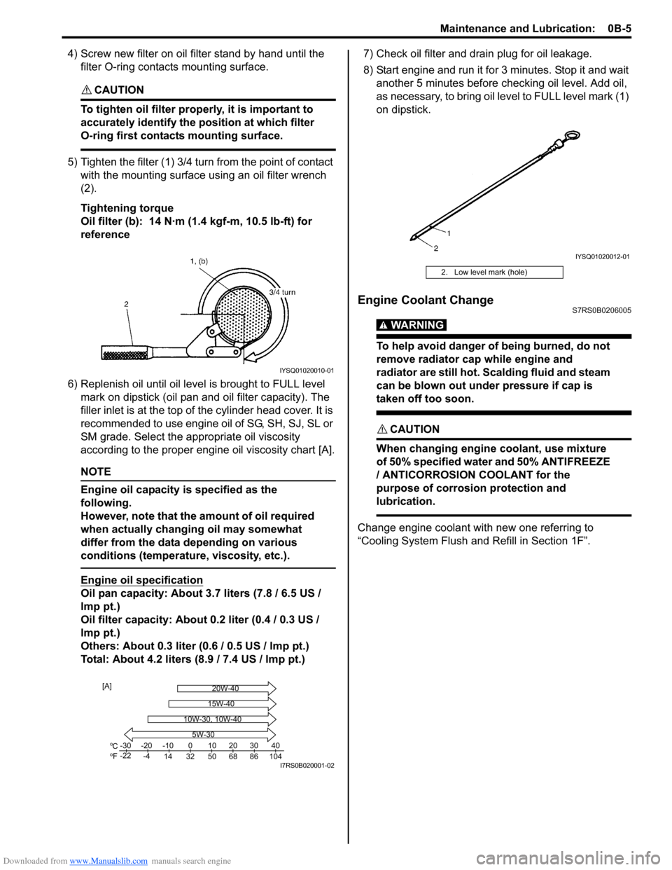
4) Screw new filter on oil filter stand by hand until the filter O-ring contacts mounting surface.
CAUTION!
To tighten oil filter prop erly, it is important to
accurately identify the position at which filter
O-ring first contacts mounting surface.
5) Tighten the filter (1) 3/4 tu rn from the point of contact
with the mounting surface using an oil filter wrench
(2).
Tightening torque
Oil filter (b): 14 N·m (1 .4 kgf-m, 10.5 lb-ft) for
reference
6) Replenish oil until oil leve l is brought to FULL level
mark on dipstick (oil pan and oil filter capacity). The
filler inlet is at the top of the cylinder head cover. It is
recommended to use engine oil of SG, SH, SJ, SL or
SM grade. Select the appropriate oil viscosity
according to the proper engine oil viscosity chart [A].
NOTE
Engine oil capacity is specified as the
following.
However, note that the amount of oil required
when actually changing oil may somewhat
differ from the data depending on various
conditions (temperature, viscosity, etc.).
Engine oil specification
Oil pan capacity: About 3.7 liters (7.8 / 6.5 US /
lmp pt.)
Oil filter capacity: About 0.2 liter (0.4 / 0.3 US /
lmp pt.)
Others: About 0.3 liter (0 .6 / 0.5 US / lmp pt.)
Total: About 4.2 liters (8.9 / 7.4 US / lmp pt.) 7) Check oil filter and drain plug for oil leakage.
8) Start engine and run it for 3 minutes. Stop it and wait
another 5 minutes before checking oil level. Add oil,
as necessary, to bring oil le vel to FULL level mark (1)
on dipstick.
Engine Coolant ChangeS7RS0B0206005
WARNING!
To help avoid danger of being burned, do not
remove radiator cap while engine and
radiator are still hot. Scalding fluid and steam
can be blown out under pressure if cap is
taken off too soon.
CAUTION!
When changing engine coolant, use mixture
of 50% specified water and 50% ANTIFREEZE
/ ANTICORROSION COOLANT for the
purpose of corrosion protection and
lubrication.
Change engine coolant with new one referring to
“Cooling System Flush and Refill in Section 1F”.
IYSQ01020010-01
Co
Fo-30
-22 -20
-4 -10
14 32 50 68 86 104 010203040
5W-30
20W-40
15W-40
10W-30, 10W-40
[A]
I7RS0B020001-02
2. Low level mark (hole)
IYSQ01020012-01
Page 48 of 1496

Downloaded from www.Manualslib.com manuals search engine 1-iv Table of Contents
Engine Lubrication System.....................1E-1
General Description ............................................. 1E-1
Engine Lubrication Description ........................... 1E-1
Diagnostic Information and Procedures ............ 1E-2 Oil Pressure Check ............................................. 1E-2
Repair Instructions ........... ................................... 1E-3
Heat Exchanger Components ............................. 1E-3
Heat Exchanger On-Vehicle Inspection .............. 1E-4
Heat Exchanger Removal and Installation .......... 1E-4
Oil Pan and Oil Pump Strainer Components....... 1E-5
Oil Pan and Oil Pump Strainer Removal and
Installation ......................................................... 1E-5
Oil Pan and Oil Pump Stra iner Cleaning ............. 1E-7
Oil Pump Components ........................................ 1E-8
Oil Pump Removal and Installation ..................... 1E-8
Oil Pump Disassembly and Reassembly ............ 1E-8
Oil Pump Inspection ............................................ 1E-9
Specifications .... ................................................. 1E-11
Tightening Torque Specifications ...................... 1E-11
Special Tools and Equipmen t ........................... 1E-11
Recommended Service Material ....................... 1E-11
Special Tool ...................................................... 1E-11
Engine Cooling System ..... ...................... 1F-1
General Description .......... ................................... 1F-1
Cooling System Descriptio n ................................ 1F-1
Coolant Description ............................................. 1F-1
Schematic and Routing Diagram ........................ 1F-2 Coolant Circulation .............................................. 1F-2
Diagnostic Information and Procedures ............ 1F-4 Engine Cooling Symptom Diagnosis ................... 1F-4
Repair Instructions ........... ................................... 1F-5
Cooling System Components.............................. 1F-5
Coolant Level Check ........................................... 1F-6
Engine Cooling System Inspection and Cleaning ............................................................ 1F-6
Cooling System Draining.. ................................... 1F-6
Cooling System Flush and Refill ......................... 1F-7
Cooling Water Pipes or Hoses Removal and Installation ......................................................... 1F-7
Thermostat Removal and In stallation.................. 1F-8
Thermostat Inspection......................................... 1F-8
Radiator Cooling Fan Motor On-Vehicle Inspection .......................................................... 1F-9
Radiator Cooling Fan Rela y Inspection............... 1F-9
Radiator Cooling Fan Removal and Installation ....................................................... 1F-10
Radiator On-Vehicle Inspection and Cleaning .. 1F-10
Radiator Removal and Inst allation .................... 1F-10
Water Pump Removal and In stallation .............. 1F-11
Water Pump Inspection ..................................... 1F-11
Specifications .... ................................................. 1F-12
Tightening Torque Specifications ...................... 1F-12
Special Tools and Equipmen t ........................... 1F-12
Recommended Service Material ....................... 1F-12
Fuel System ................... .......................... 1G-1
Precautions.......................................................... 1G-1 Precautions on Fuel System Service ................. 1G-1
General Description ............................................ 1G-1 Fuel System Description .................................... 1G-1
Fuel Delivery System Description ...................... 1G-1
Fuel Pump Description ....................................... 1G-2
Schematic and Routing Diagram ....................... 1G-2 Fuel Delivery System Diag ram........................... 1G-2
Diagnostic Information and Procedures ........... 1G-2 Fuel Pressure Inspection ................................... 1G-2
Fuel Cut Operation Inspection ........................... 1G-3
Repair Instructions ............ ................................. 1G-4
Fuel System Components .................................. 1G-4
Fuel Hose Disconnecting and Reconnecting ..... 1G-5
Fuel Pressure Relief Procedure ......................... 1G-7
Fuel Leakage Check Procedure......................... 1G-7
Fuel Lines On-Vehicle Inspection ...................... 1G-7
Fuel Pipe Removal and Installation.................... 1G-7
Fuel Injector On-Vehicle Inspection ................... 1G-8
Fuel Injector Removal and Installation ............... 1G-8
Fuel Injector Inspection ...................................... 1G-9
Fuel Filler Cap Inspection . ............................... 1G-10
Fuel Tank Inlet Valve Removal and Installation ...................................................... 1G-11
Fuel Tank Inlet Valve Inspection ...................... 1G-12
Fuel Tank Removal and Installation ................. 1G-12
Fuel Tank Inspection ........................................ 1G-13
Fuel Tank Purging Procedure .......................... 1G-14
Fuel Pump On-Vehicle Inspection.................... 1G-14
Fuel Pump Assembly Removal and Installation ...................................................... 1G-14
Main Fuel Level Sensor Removal and Installation ...................................................... 1G-15
Fuel Pump Inspection ...................................... 1G-16
Specifications ..................... ............................... 1G-16
Tightening Torque Specifications ..................... 1G-16
Special Tools and Equipmen t .......................... 1G-17
Special Tool ..................................................... 1G-17
Ignition System .............. .......................... 1H-1
General Description .............................................1H-1
Ignition System Construction ..............................1H-1
Schematic and Routing Diagram ........................1H-2 Ignition System Wiring Circuit Diagram...............1H-2
Component Location ............ ...............................1H-3
Ignition System Components Location................1H-3
Diagnostic Information and Procedures ............1H-4 Ignition System Symptom Diagnosis...................1H-4
Reference Waveform of Ignition System.............1H-4
Ignition System Check ........................................1H-4
Ignition Spark Test ..............................................1H-6
Repair Instructions ............ ..................................1H-6
High-Tension Cord Removal and Installation......1H-6
High-Tension Cord Inspection.............................1H-7
Spark Plug Removal and Installation ..................1H-7
Spark Plug Inspection .........................................1H-7
Ignition Coil Assembly (Including ignitor)
Removal and Installation ...................................1H-8
Ignition Coil Assembly (Including ignitor)
Inspection ..........................................................1H-8
Page 279 of 1496
Downloaded from www.Manualslib.com manuals search engine Engine Electrical Devices: 1C-7
Installation
Reverse removal procedure noting the following.
• Clean mating surfaces of ECT sensor and thermostat case.
• Check O-ring for damage and replace, if necessary.
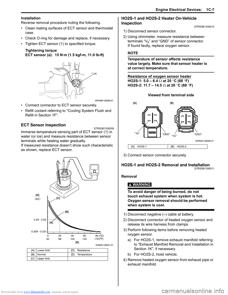
• Tighten ECT sensor (1) to specified torque.
Tightening torque
ECT sensor (a): 15 N·m (1.5 kgf-m, 11.0 lb-ft)
• Connect connector to ECT sensor securely.
• Refill coolant referring to “Cooling System Flush and
Refill in Section 1F”.
ECT Sensor InspectionS7RS0B1306009
Immerse temperature sensing part of ECT sensor (1) in
water (or ice) and measure resistance between sensor
terminals while heating water gradually.
If measured resistance doesn’t show such characteristic
as shown, replace ECT sensor.
HO2S-1 and HO2S-2 Heater On-Vehicle
Inspection
S7RS0B1306010
1) Disconnect sensor connector.
2) Using ohmmeter, measure resistance between terminals “V
B” and “GND” of sensor connector.
If found faulty, replace oxygen sensor.
NOTE
Temperature of sensor affects resistance
value largely. Make sure that sensor heater is
at correct temperature.
Resistance of oxygen sensor heater
HO2S-1: 5.0 – 6.4 Ω at 20 °C (68 °F)
HO2S-2: 11.7 – 14.5 Ω at 20 °C (68 °F)
Viewed from terminal side
3) Connect sensor co nnector securely.
HO2S-1 and HO2S-2 Removal and InstallationS7RS0B1306011
Removal
WARNING!
To avoid danger of being burned, do not
touch exhaust system when system is hot.
Oxygen sensor removal should be performed
when system is cool.
1) Disconnect negative (–) cable at battery.
2) Disconnect connector of heated oxygen sensor and
release its wire harness from clamps.
3) Perform following items before removing heated oxygen sensor.
a) For HO2S-1, remove exhaust manifold referring to “Exhaust Manifold Remo val and Installation in
Section 1K”, if necessary.
b) For HO2S-2, hoist vehicle.
4) Remove heated oxygen sensor from exhaust pipe or exhaust manifold.
[A]: Lower limit [D]: Resistance
[B]: Normal [E]: Temperature
[C]: Upper limit
1,(a)
I2RH0B130009-01
20
0
68
32 104 140 176 40 60 80
[E]
2.29 - 2.62
0.309 - 0.331
[A]
[B]
[C][D]
I5JB0A130037-01
[A]: HO2S-1 [B]: HO2S-2
I4RS0A130006-01
Page 298 of 1496
Downloaded from www.Manualslib.com manuals search engine 1D-13 Engine Mechanical:
Throttle Body On-Vehicle InspectionS7RS0B1406006
Check electric throttle body assembly referring to
“Throttle Valve Operation Check” and “Electric Throttle
Body Assembly Operation Check” under “Electric
Throttle Body Assembly On-Vehicle Inspection in
Section 1C”.
Electric Throttle Body Assembly Removal and
Installation
S7RS0B1406007
CAUTION!
Never disassemble electric throttle body.
Disassembly will spoil its original
performance. If faulty condition is found,
replace it with new one.
NOTE
After replacing electric throttle body
assembly, perform calibration of throttle
valve referring to “Electric Throttle Body
System Calibration in Section 1C”.
Removal
1) Disconnect negative cable at battery.
2) Drain coolant referring to “Cooling System Draining in Section 1F”.
3) Remove air cleaner assembly referring to “Air Cleaner Components”.
4) Detach EVAP canister and purge valve chamber, and remove air cleaner outlet hose.
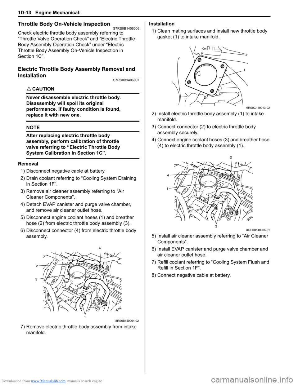
5) Disconnect engine coolant hoses (1) and breather hose (2) from electric throttle body assembly (3).
6) Disconnect connector (4) from electric throttle body assembly.
7) Remove electric throttle body assembly from intake
manifold. Installation
1) Clean mating surfaces and install new throttle body gasket (1) to intake manifold.
2) Install electric throttle bo dy assembly (1) to intake
manifold.
3) Connect connector (2) to electric throttle body assembly securely.
4) Connect engine coolant hoses (3) and breather hose (4) to electric thrott le body assembly (1).
5) Install air cleaner assembly referring to “Air Cleaner
Components”.
6) Install EVAP canister and purge valve chamber and air cleaner outlet hose.
7) Refill coolant referring to “Cooling System Flush and
Refill in Section 1F”.
8) Connect negative cable at battery.
2
4
3
1I4RS0B140004-02
1
I6RS0C140013-02
4
2
1
3I4RS0B140006-01
Page 300 of 1496
Downloaded from www.Manualslib.com manuals search engine 1D-15 Engine Mechanical:
Installation
Reverse removal procedure for installation noting the
followings.
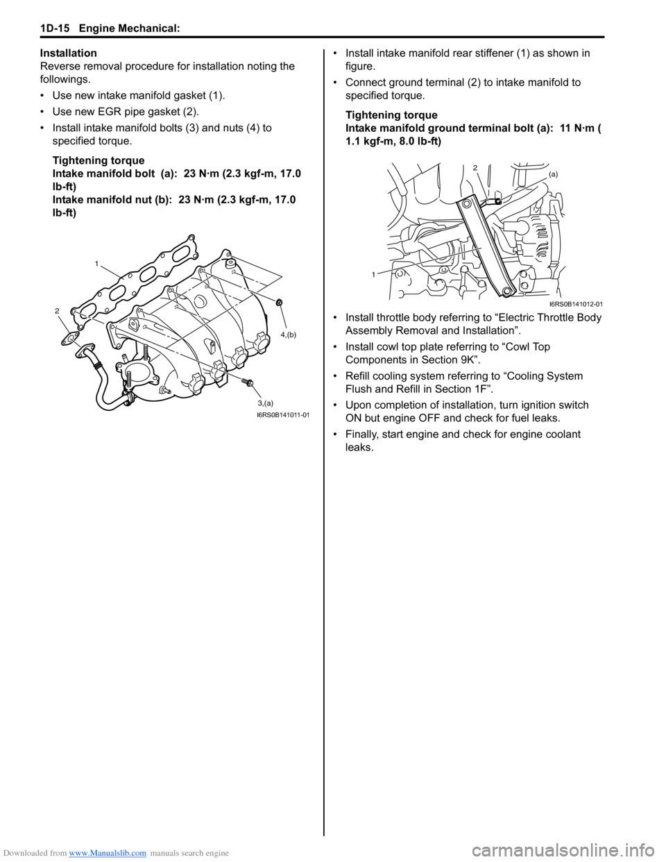
• Use new intake manifold gasket (1).
• Use new EGR pipe gasket (2).
• Install intake manifold bolts (3) and nuts (4) to specified torque.
Tightening torque
Intake manifold bolt (a): 23 N·m (2.3 kgf-m, 17.0
lb-ft)
Intake manifold nut (b): 23 N·m (2.3 kgf-m, 17.0
lb-ft) • Install intake manifold rear stiffener (1) as shown in
figure.
• Connect ground terminal (2) to intake manifold to specified torque.
Tightening torque
Intake manifold ground terminal bolt (a): 11 N·m (
1.1 kgf-m, 8.0 lb-ft)
• Install throttle body referrin g to “Electric Throttle Body
Assembly Removal and Installation”.
• Install cowl top plate referring to “Cowl Top Components in Section 9K”.
• Refill cooling system refe rring to “Cooling System
Flush and Refill in Section 1F”.
• Upon completion of installation, turn ignition switch ON but engine OFF and check for fuel leaks.
• Finally, start engine and check for engine coolant leaks.
1
2
3,(a)
4,(b)
I6RS0B141011-01
(a)
12
I6RS0B141012-01
Page 305 of 1496
Downloaded from www.Manualslib.com manuals search engine Engine Mechanical: 1D-20
15) Install A/C compressor to its bracket (if equipped) referring to “Compressor Assembly Removal and
Installation in Section 7B” or “Compressor Assembly
Removal and Installa tion in Section 7B”.
16) Adjust A/C compressor belt tension (if equipped) referring to “Compressor Drive Belt Inspection and
Adjustment in Section 7B” or “Compressor Drive Belt
Inspection and Adjustment in Section 7B”.
17) Check to ensure that a ll removed parts are back in
place.
Reinstall any necessary parts which have not been
reinstalled.
18) Refill cooling system with coolant referring to “Cooling System Flush and Refill in Section 1F”. 19) Refill engine with engine oil
referring to “Engine Oil
and Filter Change in Section 0B”.
20) Refill transaxle with transa xle oil referring to“Manual
Transaxle Oil Change in Section 5B” or “A/T Fluid
Change in Section 5A”.
21) Install battery and tray.
22) Connect positive and negative cable at battery.
23) Install engine hood and connect windshield washer hose.
24) Verify that there is no fu el leakage, coolant leakage,
oil leakage and exhaust gas leakage at each
connection.
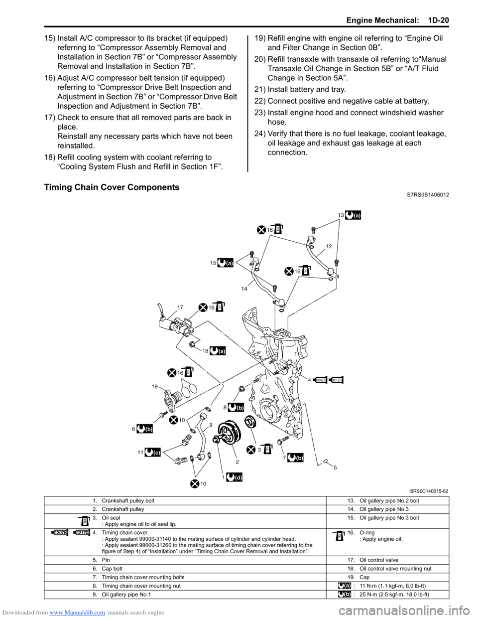
Timing Chain Cover ComponentsS7RS0B1406012
I6RS0C140015-02
1. Crankshaft pulley bolt 13. Oil gallery pipe No.2 bolt
2. Crankshaft pulley 14. Oil gallery pipe No.3
3. Oil seal : Apply engine oil to oil seal lip. 15. Oil gallery pipe No.3 bolt
4. Timing chain cover : Apply sealant 99000-31140 to the mating surface of cylinder and cylinder head.
: Apply sealant 99000-31260 to the mating surface of timing chain cover referring to the
figure of Step 4) of “Installation” under “Timing Chain Cover Removal and Installation”. 16. O-ring
: Apply engine oil.
5. Pin 17. Oil control valve
6. Cap bolt 18. Oil control valve mounting nut
7. Timing chain cover mounting bolts 19. Cap
8. Timing chain cover mounting nut : 11 N ⋅m (1.1 kgf-m, 8.0 lb-ft)
9. Oil gallery pipe No.1 :25 N⋅m (2.5 kgf-m, 18.0 lb-ft)
Page 356 of 1496
Downloaded from www.Manualslib.com manuals search engine 1E-4 Engine Lubrication System:
Heat Exchanger On-Vehicle InspectionS7RS0B1506002
• Check heat exchanger for deformation wear or damage.
• Check heat exchanger for coolant leakage and oil leakage.
If any malcondition is found, replace O-ring, stand bolt
gasket and/or heat exchanger.
Heat Exchanger Removal and InstallationS7RS0B1506003
Removal
1) Drain engine oil by removing drain plug.
2) Drain coolant referring to “Cooling System Draining in Section 1F”.
3) Remove exhaust manifold referring to “Exhaust Manifold Removal and Inst allation in Section 1K”.
4) Remove heat exchanger inlet No. 1 hose and outlet No. 1 hose.
5) Remove heat exchanger, O-ring and gasket by removing heat exchanger stand bolt. Installation
Reverse removal procedure for installation noting the
followings.
• Use new stand bolt gasket.
• Apply engine oil to new O-ring and install it to heat
exchanger.
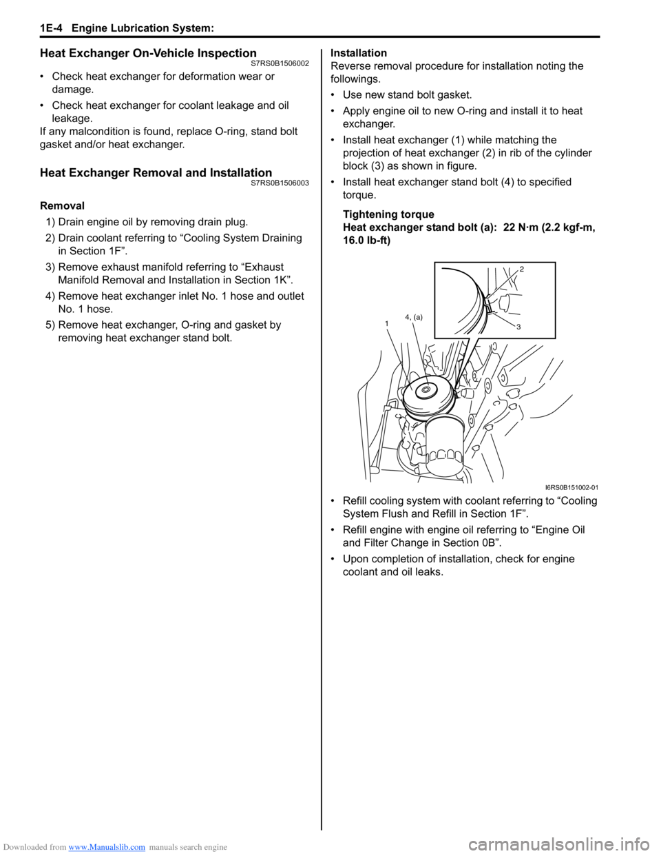
• Install heat exchanger (1) while matching the projection of heat exchanger (2) in rib of the cylinder
block (3) as shown in figure.
• Install heat exchanger stand bolt (4) to specified torque.
Tightening torque
Heat exchanger stand bolt (a): 22 N·m (2.2 kgf-m,
16.0 lb-ft)
• Refill cooling system with co olant referring to “Cooling
System Flush and Refill in Section 1F”.
• Refill engine with engine oil referring to “Engine Oil and Filter Change in Section 0B”.
• Upon completion of installation, check for engine coolant and oil leaks.
2
3
4, (a)
1
I6RS0B151002-01
Page 370 of 1496
Downloaded from www.Manualslib.com manuals search engine 1F-7 Engine Cooling System:
Cooling System Flush and RefillS7RS0B1606005
WARNING!
To help avoid danger of being burned, do not
remove radiator cap while engine and
radiator are still hot. Scalding fluid and steam
can be blown out under pressure if cap is
taken off too soon.
NOTE
For detail of coolant specification, refer to
“Coolant Description”.
1) Remove radiator cap when engine is cool as follows.a) Turn cap counterclockwise slowly until it reaches a “stop” (Do not press down while turning it).
b) Wait until pressure is relieved (indicated by a hissing sound) then press down on cap and
continue to turn it counterclockwise.
2) With radiator cap removed, run engine until upper radiator hose is hot (this shows that thermostat is
open and coolant is flowing through system).
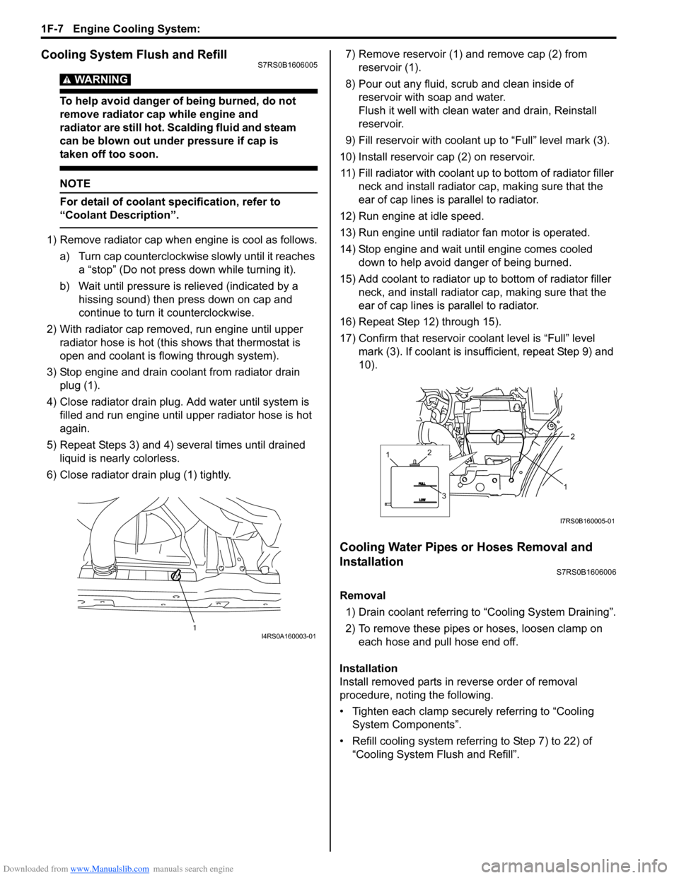
3) Stop engine and drain coolant from radiator drain plug (1).
4) Close radiator drain plug. Add water until system is filled and run engine until up per radiator hose is hot
again.
5) Repeat Steps 3) and 4) several times until drained liquid is nearly colorless.
6) Close radiator drain plug (1) tightly. 7) Remove reservoir (1) and remove cap (2) from
reservoir (1).
8) Pour out any fluid, scrub and clean inside of reservoir with soap and water.
Flush it well with clean water and drain, Reinstall
reservoir.
9) Fill reservoir with coolant up to “Full” level mark (3).
10) Install reservoir cap (2) on reservoir. 11) Fill radiator with coolant up to bottom of radiator filler neck and install radiator cap, making sure that the
ear of cap lines is parallel to radiator.
12) Run engine at idle speed.
13) Run engine until radiator fan motor is operated.
14) Stop engine and wait until engine comes cooled down to help avoid danger of being burned.
15) Add coolant to radiator up to bottom of radiator filler
neck, and install radiator ca p, making sure that the
ear of cap lines is parallel to radiator.
16) Repeat Step 12) through 15).
17) Confirm that reservoir cool ant level is “Full” level
mark (3). If coolant is insu fficient, repeat Step 9) and
10).
Cooling Water Pipes or Hoses Removal and
Installation
S7RS0B1606006
Removal
1) Drain coolant referring to “Cooling System Draining”.
2) To remove these pipes or hoses, loosen clamp on each hose and pull hose end off.
Installation
Install removed parts in reverse order of removal
procedure, noting the following.
• Tighten each clamp securely referring to “Cooling System Components”.
• Refill cooling system referrin g to Step 7) to 22) of
“Cooling System Flush and Refill”.
1I4RS0A160003-01
1
2
1
3
2
I7RS0B160005-01
Page 371 of 1496
Downloaded from www.Manualslib.com manuals search engine Engine Cooling System: 1F-8
Thermostat Removal and InstallationS7RS0B1606007
Removal1) Drain coolant referring to “Cooling System Draining”.
2) Remove intake manifold referring to “Intake Manifold Removal and Installa tion in Section 1D”.
3) Remove generator referring to “Generator Dismounting and Remounting in Section 1J”.
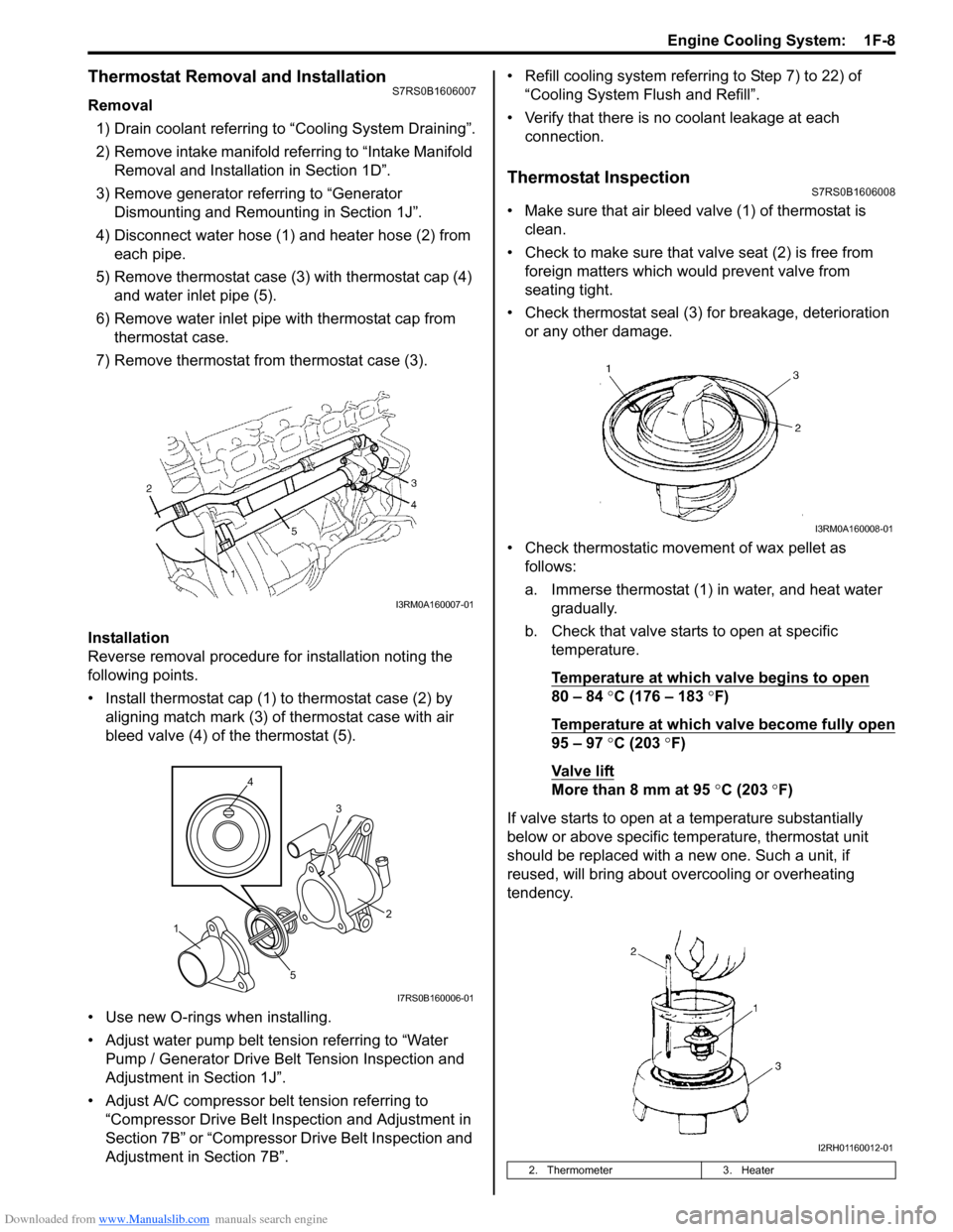
4) Disconnect water hose (1) and heater hose (2) from each pipe.
5) Remove thermostat case (3) with thermostat cap (4)
and water inlet pipe (5).
6) Remove water inlet pipe with thermostat cap from thermostat case.
7) Remove thermostat from thermostat case (3).
Installation
Reverse removal procedure for installation noting the
following points.
• Install thermostat cap (1) to thermostat case (2) by aligning match mark (3) of thermostat case with air
bleed valve (4) of the thermostat (5).
• Use new O-rings when installing.
• Adjust water pump belt tension referring to “Water Pump / Generator Drive Belt Tension Inspection and
Adjustment in Section 1J”.
• Adjust A/C compressor belt tension referring to “Compressor Drive Belt Inspection and Adjustment in
Section 7B” or “Compressor Drive Belt Inspection and
Adjustment in Section 7B”. • Refill cooling system referrin
g to Step 7) to 22) of
“Cooling System Flush and Refill”.
• Verify that there is no coolant leakage at each connection.
Thermostat InspectionS7RS0B1606008
• Make sure that air bleed valve (1) of thermostat is clean.
• Check to make sure that va lve seat (2) is free from
foreign matters which would prevent valve from
seating tight.
• Check thermostat seal (3) for breakage, deterioration or any other damage.
• Check thermostatic movement of wax pellet as follows:
a. Immerse thermostat (1) in water, and heat water gradually.
b. Check that valve starts to open at specific temperature.
Temperature at which valve begins to open
80 – 84 °C (176 – 183 °F)
Temperature at which valve become fully open
95 – 97 °C (203 °F)
Va l v e l i ft
More than 8 mm at 95 °C (203 ° F)
If valve starts to open at a temperature substantially
below or above specific temperature, thermostat unit
should be replaced with a new one. Such a unit, if
reused, will bring about ov ercooling or overheating
tendency.
I3RM0A160007-01
4
5 3
1 2
I7RS0B160006-01
2. Thermometer
3. Heater
I3RM0A160008-01
I2RH01160012-01
Page 373 of 1496
Downloaded from www.Manualslib.com manuals search engine Engine Cooling System: 1F-10
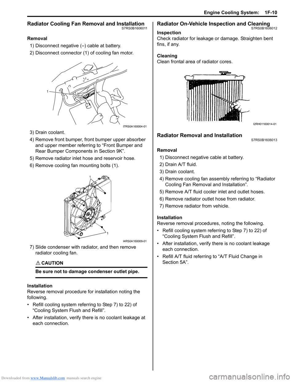
Radiator Cooling Fan Removal and InstallationS7RS0B1606011
Removal1) Disconnect negative (–) cable at battery.
2) Disconnect connector (1) of cooling fan motor.
3) Drain coolant.
4) Remove front bumper, front bumper upper absorber and upper member referring to “Front Bumper and
Rear Bumper Componen ts in Section 9K”.
5) Remove radiator inlet hose and reservoir hose.
6) Remove cooling fan mounting bolts (1).
7) Slide condenser with radiator, and then remove radiator cooling fan.
CAUTION!
Be sure not to damage condenser outlet pipe.
Installation
Reverse removal procedure for installation noting the
following.
• Refill cooling system referring to Step 7) to 22) of “Cooling System Fl ush and Refill”.
• After installation, verify there is no coolant leakage at each connection.
Radiator On-Vehicle Inspection and CleaningS7RS0B1606012
Inspection
Check radiator for leakage or damage. Straighten bent
fins, if any.
Cleaning
Clean frontal area of radiator cores.
Radiator Removal and InstallationS7RS0B1606013
Removal
1) Disconnect negative cable at battery.
2) Drain A/T fluid.
3) Drain coolant.
4) Remove cooling fan assemb ly referring to “Radiator
Cooling Fan Removal and Installation”.
5) Remove A/T fluid cooler inlet and outlet hoses.
6) Remove radiator outlet hose from radiator.
7) Remove radiator from vehicle.
Installation
Reverse removal procedures, noting the following.
• Refill cooling system referrin g to Step 7) to 22) of
“Cooling System Flush and Refill”.
• After installation, verify there is no coolant leakage each connection.
• Refill A/T fluid referring to “A/T Fluid Change in
Section 5A”.
1
I7RS0A160004-01
I4RS0A160009-01
I2RH01160014-01