front ligh SUZUKI SWIFT 2007 2.G Service Workshop Manual
[x] Cancel search | Manufacturer: SUZUKI, Model Year: 2007, Model line: SWIFT, Model: SUZUKI SWIFT 2007 2.GPages: 1496, PDF Size: 34.44 MB
Page 4 of 1496

Downloaded from www.Manualslib.com manuals search engine 00
0
1
2
3
4
5
6
7
8
9
10
11
Vo l u m e 1
Precautions............................................................... 00-iPrecautions ............................................................ 00-1
General Information ................ ................................... 0-i
General Information ............................................... 0A-1
Maintenance and Lubricatio n ................................. 0B-1
Engine ......................................................................... 1-i Precautions .............................................................. 1-1
Engine General Information and Diagnosis ........... 1A-1
Aux. Emission Control Devices .............................. 1B-1
Engine Electrical Devices....................................... 1C-1
Engine Mechanical ................................................. 1D-1
Engine Lubrication System .................................... 1E-1
Engine Cooling System .......................................... 1F-1
Fuel System ...........................................................1G-1
Ignition System....................................................... 1H-1
Starting System ....................................................... 1I-1
Charging System.....................................................1J-1
Exhaust System ..................................................... 1K-1
Suspension ................................................................. 2-i Precautions .............................................................. 2-1
Suspension General Diagnosis .............................. 2A-1
Front Suspension ................................................... 2B-1
Rear Suspension................ .................................... 2C-1
Wheels and Tires ................................................... 2D-1
Driveline / Axle ........................................................... 3-i Precautions .............................................................. 3-1
Drive Shaft / Axle ................................................... 3A-1
Brakes ......................................................................... 4-i Precautions .............................................................. 4-1
Brake Control System and Diagnosis .................... 4A-1
Front Brakes........................................................... 4B-1
Rear Brakes ........................................................... 4C-1
Parking Brake......................................................... 4D-1
ABS ........................................................................ 4E-1
Electronic Stability Program ................................... 4F-1
Vo l u m e 2
Precautions ............................................................... 00-iPrecautions ............................................................ 00-1
Transmission / Transaxle .... ...................................... 5-i
Precautions .............................................................. 5-1
Automatic Transmission/Transaxle ........................ 5A-1
Manual Transmission/Transaxle ............................ 5B-1
Clutch .....................................................................5C-1
Steering ....................................................................... 6-i Precautions .............................................................. 6-1
Steering General Diagnosis ................................... 6A-1
Steering Wheel and Column .................................. 6B-1
Power Assisted Steering System ...........................6C-1
HVAC ........................................................................... 7-i Precautions .............................................................. 7-1
Heater and Ventilation............................................ 7A-1
Air Conditioning System ......................................... 7B-1
Restraint ...................................................................... 8-i Precautions .............................................................. 8-1
Seat Belts ............................................................... 8A-1
Air Bag System ...................................................... 8B-1
Body, Cab and Accessories .... .................................. 9-i
Precautions .............................................................. 9-1
Wiring Systems ...................................................... 9A-1
Lighting Systems .................................................... 9B-1
Instrumentation / Driver Info. / Horn .......................9C-1
Wipers / Washers ...................................................9D-1
Glass / Windows / Mirrors ...................................... 9E-1
Security and Locks ................................................. 9F-1
Seats ..................................................................... 9G-1
Interior Trim ............................................................9H-1
Hood / Fenders / Doors .......................................... 9J-1
Body Structure ....................................................... 9K-1
Paint / Coatings ...................................................... 9L-1
Exterior Trim .......................................................... 9M-1
Control Systems ....................................................... 10-i Precautions ............................................................ 10-1
Body Electrical Control Sy stem ............................ 10B-1
Immobilizer Control System .................................10C-1
Keyless Start System ........................................... 10E-1
TABLE OF CONTENTS
Page 8 of 1496
Downloaded from www.Manualslib.com manuals search engine 00-3 Precautions:
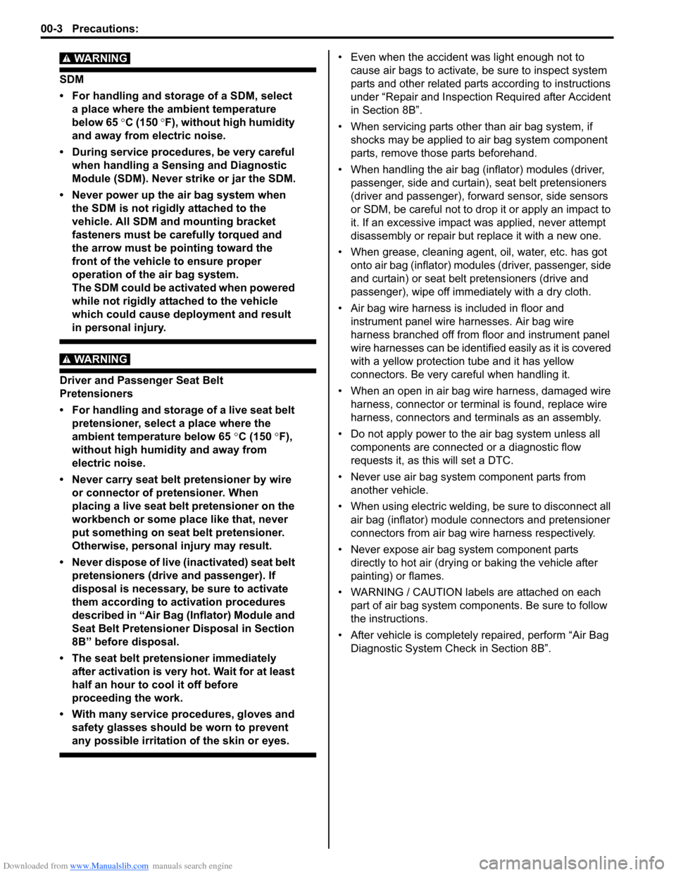
WARNING!
SDM
• For handling and storage of a SDM, select a place where the ambient temperature
below 65 °C (150 °F), without high humidity
and away from electric noise.
• During service procedures, be very careful when handling a Sensing and Diagnostic
Module (SDM). Never strike or jar the SDM.
• Never power up the air bag system when the SDM is not rigidly attached to the
vehicle. All SDM and mounting bracket
fasteners must be carefully torqued and
the arrow must be pointing toward the
front of the vehicle to ensure proper
operation of the air bag system.
The SDM could be activated when powered
while not rigidly att ached to the vehicle
which could cause deployment and result
in personal injury.
WARNING!
Driver and Passenger Seat Belt
Pretensioners
• For handling and storage of a live seat belt pretensioner, select a place where the
ambient temperature below 65 °C (150 ° F),
without high humidity and away from
electric noise.
• Never carry seat belt pretensioner by wire or connector of pretensioner. When
placing a live seat belt pretensioner on the
workbench or some place like that, never
put something on seat belt pretensioner.
Otherwise, personal injury may result.
• Never dispose of live (inactivated) seat belt pretensioners (drive and passenger). If
disposal is necessary, be sure to activate
them according to activation procedures
described in “Air Bag (Inflator) Module and
Seat Belt Pretensioner Disposal in Section
8B” before disposal.
• The seat belt pretensioner immediately after activation is very hot. Wait for at least
half an hour to cool it off before
proceeding the work.
• With many service procedures, gloves and safety glasses should be worn to prevent
any possible irritation of the skin or eyes.
• Even when the accident was light enough not to cause air bags to activate, be sure to inspect system
parts and other related parts according to instructions
under “Repair and Inspection Required after Accident
in Section 8B”.
• When servicing parts other than air bag system, if shocks may be applied to air bag system component
parts, remove those parts beforehand.
• When handling the air bag (inflator) modules (driver, passenger, side and curtain), seat belt pretensioners
(driver and passenger), forward sensor, side sensors
or SDM, be careful not to drop it or apply an impact to
it. If an excessive impact was applied, never attempt
disassembly or repair but replace it with a new one.
• When grease, cleaning agent, oil, water, etc. has got onto air bag (inflator) modules (driver, passenger, side
and curtain) or seat belt pretensioners (drive and
passenger), wipe off immediately with a dry cloth.
• Air bag wire harness is included in floor and instrument panel wire harnesses. Air bag wire
harness branched off from floor and instrument panel
wire harnesses can be identifie d easily as it is covered
with a yellow protection tube and it has yellow
connectors. Be very ca reful when handling it.
• When an open in air bag wire harness, damaged wire harness, connector or terminal is found, replace wire
harness, connectors and terminals as an assembly.
• Do not apply power to the air bag system unless all components are connected or a diagnostic flow
requests it, as this will set a DTC.
• Never use air bag system component parts from another vehicle.
• When using electric welding, be sure to disconnect all air bag (inflator) module connectors and pretensioner
connectors from air bag wire harness respectively.
• Never expose air bag system component parts directly to hot air (drying or baking the vehicle after
painting) or flames.
• WARNING / CAUTION labels are attached on each
part of air bag system components. Be sure to follow
the instructions.
• After vehicle is completely repaired, perform “Air Bag Diagnostic System Check in Section 8B”.
Page 37 of 1496
Downloaded from www.Manualslib.com manuals search engine Maintenance and Lubrication: 0B-7
Fuel Filter ReplacementS7RS0B0206011
Fuel filter is installed in fuel pump assembly in fuel tank.
Replace fuel filter or fuel pump assembly with new one,
referring to “Fuel Pump Assembly Removal and
Installation in Section 1G” for proper procedure.
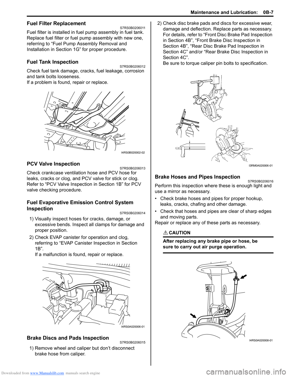
Fuel Tank InspectionS7RS0B0206012
Check fuel tank damage, cracks, fuel leakage, corrosion
and tank bolts looseness.
If a problem is found, repair or replace.
PCV Valve InspectionS7RS0B0206013
Check crankcase ventilation hose and PCV hose for
leaks, cracks or clog, and PCV valve for stick or clog.
Refer to “PCV Valve Inspection in Section 1B” for PCV
valve checking procedure.
Fuel Evaporative Emission Control System
Inspection
S7RS0B0206014
1) Visually inspect hoses for cracks, damage, or excessive bends. Inspect a ll clamps for damage and
proper position.
2) Check EVAP canister for operation and clog, referring to “EVAP Canister Inspection in Section
1B”.
If a malfunction is found, repair or replace.
Brake Discs and Pads InspectionS7RS0B0206015
1) Remove wheel and caliper but don’t disconnect brake hose from caliper. 2) Check disc brake pads and discs for excessive wear,
damage and deflection. Replace parts as necessary.
For details, refer to “Front Disc Brake Pad Inspection
in Section 4B”, “Front Brake Disc Inspection in
Section 4B”, “Rear Disc Brake Pad Inspection in
Section 4C” and/or “Rear Brake Disc Inspection in
Section 4C”.
Be sure to torque caliper pin bolts to specification.
Brake Hoses and Pipes InspectionS7RS0B0206016
Perform this inspection where these is enough light and
use a mirror as necessary.
• Check brake hoses and pipes for proper hookup, leaks, cracks, chafing and other damage.
• Check that hoses and pipes are clear of sharp edges and moving parts.
Repair or replace any of these parts as necessary.
CAUTION!
After replacing any brake pipe or hose, be
sure to carry out air purge operation.
I4RS0B020002-02
I4RS0A020006-01
I3RM0A020006-01
I4RS0A020008-01
Page 40 of 1496
Downloaded from www.Manualslib.com manuals search engine 0B-10 Maintenance and Lubrication:
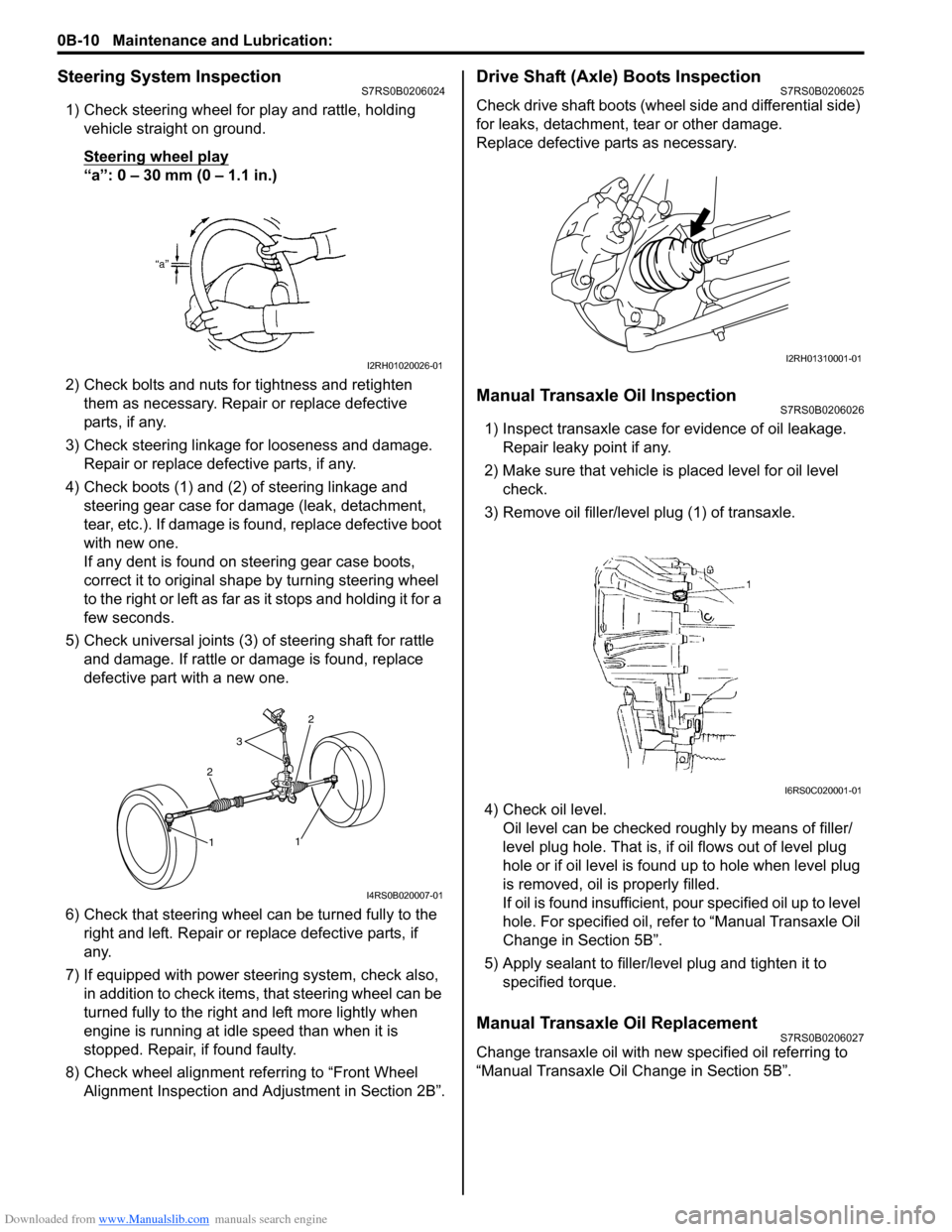
Steering System InspectionS7RS0B0206024
1) Check steering wheel for play and rattle, holding vehicle straight on ground.
Steering wheel play
“a”: 0 – 30 mm (0 – 1.1 in.)
2) Check bolts and nuts for tightness and retighten them as necessary. Repair or replace defective
parts, if any.
3) Check steering linkage for looseness and damage. Repair or replace defective parts, if any.
4) Check boots (1) and (2) of steering linkage and steering gear case for damage (leak, detachment,
tear, etc.). If damage is fo und, replace defective boot
with new one.
If any dent is found on steering gear case boots,
correct it to original shape by turning steering wheel
to the right or left as far as it stops and holding it for a
few seconds.
5) Check universal joints (3) of steering shaft for rattle and damage. If rattle or damage is found, replace
defective part with a new one.
6) Check that steering wheel can be turned fully to the
right and left. Repair or replace defective parts, if
any.
7) If equipped with power steering system, check also, in addition to check items, that steering wheel can be
turned fully to the right and left more lightly when
engine is running at idle speed than when it is
stopped. Repair, if found faulty.
8) Check wheel alignment referring to “Front Wheel Alignment Inspection and Adjustment in Section 2B”.
Drive Shaft (Axle) Boots InspectionS7RS0B0206025
Check drive shaft boots (wheel side and differential side)
for leaks, detachment, tear or other damage.
Replace defective parts as necessary.
Manual Transaxle Oil InspectionS7RS0B0206026
1) Inspect transaxle case for evidence of oil leakage. Repair leaky point if any.
2) Make sure that vehicle is placed level for oil level
check.
3) Remove oil filler/leve l plug (1) of transaxle.
4) Check oil level. Oil level can be checked roughly by means of filler/
level plug hole. That is, if oil flows out of level plug
hole or if oil level is found up to hole when level plug
is removed, oil is properly filled.
If oil is found insufficient, po ur specified oil up to level
hole. For specified oil, refe r to “Manual Transaxle Oil
Change in Section 5B”.
5) Apply sealant to filler/leve l plug and tighten it to
specified torque.
Manual Transaxle Oil ReplacementS7RS0B0206027
Change transaxle oil with new specified oil referring to
“Manual Transaxle Oil Change in Section 5B”.
I2RH01020026-01
2
3
2
1
1
I4RS0B020007-01
I2RH01310001-01
I6RS0C020001-01
Page 58 of 1496
Downloaded from www.Manualslib.com manuals search engine 1A-8 Engine General Information and Diagnosis:
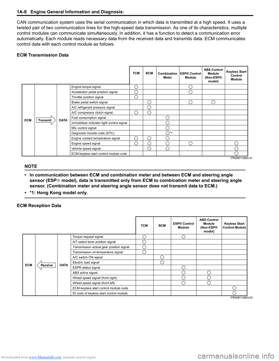
CAN communication system uses the serial communication in which data is transmitted at a high speed. It uses a
twisted pair of two communication lines for the high-speed da ta transmission. As one of its characteristics, multiple
control modules can communicate simultaneously. In addition, it has a function to detect a communication error
automatically. Each module reads necessary data from the received data and transmits data. ECM communicates
control data with each control module as follows.
ECM Transmission Data
NOTE
• In communication between ECM and combination meter and between ECM and steering angle sensor (ESP ® model), data is transmitted only from ECM to combination meter and steering angle
sensor. (Combination meter and steering angle sensor does not transmit data to ECM.)
• *1: Hong Kong model only.
ECM Reception Data
Engine torque signal
Accelerator pedal position signal
Throttle position signal
Brake pedal switch signal
A/C refrigerant pressure signal
A/C compressor clutch signal
Fuel consumption signal
Immobilizer indicator light control signal
MIL control signal
Diagnostic trouble code (DTC)
Engine coolant temperature signal
Engine speed signal
Vehicle speed signal
ECM-keyless start control module code TCM BCM
Combination
Meter Keyless Start
ControlModule
Transmit DATA
ECM
ESP® Control
Module ABS Control
Module
(Non-ESP® model)
*1
I7RS0B110002-01
TCM BCM Keyless Start
Control Module
DATA
ECM
Torque request signal
A/T select lever position signal
Transmission actual gear position signal
Transmission oil temperature signal
A/C switch ON signal
Electric load signal
ESP® status signal
ABS active signal
Wheel speed signal (front right)
Wheel speed signal (front left)
ECM-keyless start control module code
ID code of keyless start control module
Receive
ABS Control
Module
(Non-ESP® model)
ESP® Control
Module
I7RS0B110003-02
Page 495 of 1496
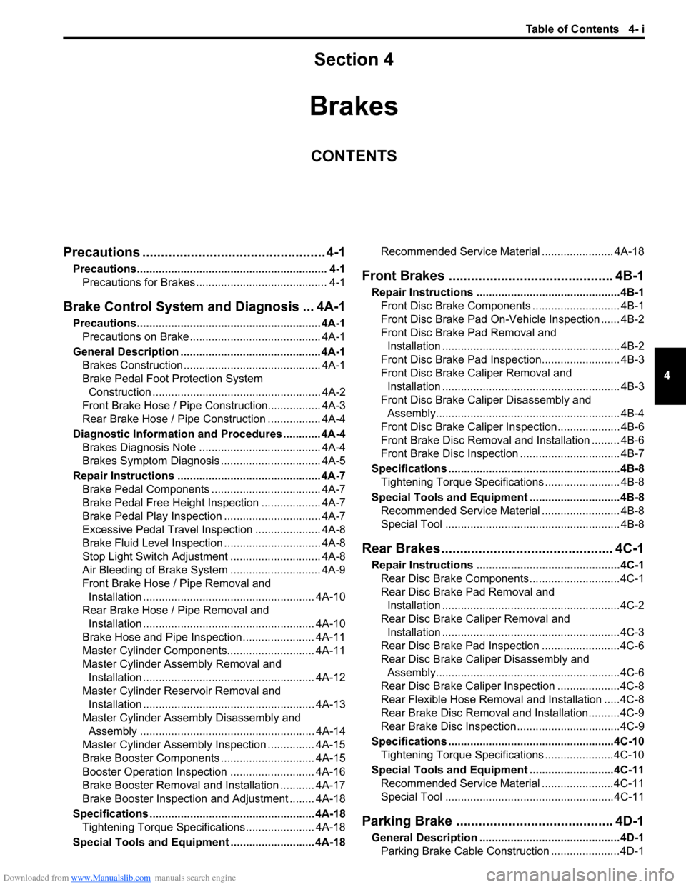
Downloaded from www.Manualslib.com manuals search engine Table of Contents 4- i
4
Section 4
CONTENTS
Brakes
Precautions ................................................. 4-1
Precautions............................................................. 4-1
Precautions for Brakes .......................................... 4-1
Brake Control System and Diagnosis ... 4A-1
Precautions........................................................... 4A-1Precautions on Brake .......................................... 4A-1
General Description ............................................. 4A-1 Brakes Construction ............................................ 4A-1
Brake Pedal Foot Protection System Construction ...................................................... 4A-2
Front Brake Hose / Pipe Co nstruction................. 4A-3
Rear Brake Hose / Pipe Construction ................. 4A-4
Diagnostic Information and Procedures ............ 4A-4 Brakes Diagnosis Note ....................................... 4A-4
Brakes Symptom Diagnosis ................................ 4A-5
Repair Instructions .............................................. 4A-7 Brake Pedal Components ................................... 4A-7
Brake Pedal Free Height Inspection ................... 4A-7
Brake Pedal Play Inspection ............................... 4A-7
Excessive Pedal Travel Inspection ..................... 4A-8
Brake Fluid Level Inspection ............................... 4A-8
Stop Light Switch Adjustment ............................. 4A-8
Air Bleeding of Brake System ............................. 4A-9
Front Brake Hose / Pipe Removal and Installation ....................................................... 4A-10
Rear Brake Hose / Pipe Removal and Installation ....................................................... 4A-10
Brake Hose and Pipe Inspection ....................... 4A-11
Master Cylinder Components............................ 4A-11
Master Cylinder Assembly Removal and Installation ....................................................... 4A-12
Master Cylinder Rese rvoir Removal and
Installation ....................................................... 4A-13
Master Cylinder Assemb ly Disassembly and
Assembly ........................................................ 4A-14
Master Cylinder Assembly Inspection ............... 4A-15
Brake Booster Components .............................. 4A-15
Booster Operation Inspection ........................... 4A-16
Brake Booster Removal and Installation ........... 4A-17
Brake Booster Inspection and Adjustment ........ 4A-18
Specifications ..................................................... 4A-18
Tightening Torque Specifications ...................... 4A-18
Special Tools and Equipmen t ........................... 4A-18 Recommended Service Material ....................... 4A-18
Front Brakes .......
..................................... 4B-1
Repair Instructions ........... ...................................4B-1
Front Disc Brake Components ............................ 4B-1
Front Disc Brake Pad On-Vehicle Inspection ...... 4B-2
Front Disc Brake Pad Removal and Installation ......................................................... 4B-2
Front Disc Brake Pad Inspection......................... 4B-3
Front Disc Brake Ca liper Removal and
Installation ......................................................... 4B-3
Front Disc Brake Caliper Disassembly and Assembly........................................................... 4B-4
Front Disc Brake Caliper In spection.................... 4B-6
Front Brake Disc Removal and Installation ......... 4B-6
Front Brake Disc Inspection ................................ 4B-7
Specifications .................... ...................................4B-8
Tightening Torque Specifications ........................ 4B-8
Special Tools and Equipmen t .............................4B-8
Recommended Service Material ......................... 4B-8
Special Tool ........................................................ 4B-8
Rear Brakes................... ........................... 4C-1
Repair Instructions ........... ...................................4C-1
Rear Disc Brake Components.............................4C-1
Rear Disc Brake Pad Removal and Installation .........................................................4C-2
Rear Disc Brake Caliper Removal and Installation .........................................................4C-3
Rear Disc Brake Pad Inspection .........................4C-6
Rear Disc Brake Caliper Disassembly and Assembly...........................................................4C-6
Rear Disc Brake Caliper Inspection ....................4C-8
Rear Flexible Hose Remova l and Installation .....4C-8
Rear Brake Disc Removal and Installation..........4C-9
Rear Brake Disc Inspection.................................4C-9
Specifications .................... .................................4C-10
Tightening Torque Specifications ......................4C-10
Special Tools and Equipmen t ...........................4C-11
Recommended Service Material .......................4C-11
Special Tool ......................................................4C-11
Parking Brake ................. ......................... 4D-1
General Description .............................................4D-1
Parking Brake Cable Construction ......................4D-1
Page 496 of 1496

Downloaded from www.Manualslib.com manuals search engine 4-ii Table of Contents
Repair Instructions ..............................................4D-2Parking Brake Inspection and Adjustment ..........4D-2
Parking Brake Cable Removal and Installation ......................................................... 4D-3
Parking Brake Lever Removal and Installation ....4D-3
Specifications .... ...................................................4D-4
Tightening Torque Specifications ........................4D-4
ABS ........................................... .................4E-1
Precautions........................................................... 4E-1
Precautions in Diagnosing Troubles ................... 4E-1
Precautions in On-Vehicle Service...................... 4E-1
Precautions in Hydraulic Unit Operation Check ................................................................ 4E-1
General Description ............................................. 4E-2 ABS Description .................................................. 4E-2
ABS Hydraulic Unit / Control Module Assembly Description ....................................... 4E-2
CAN Communication System Description........... 4E-3
Schematic and Routing Diagram ........................ 4E-4 ABS Schematic ................................................... 4E-4
ABS Wiring Circuit Diagram ................................ 4E-5
Component Location ........... ................................ 4E-7
ABS Components Location ................................. 4E-7
Front Wheel Speed Sensor Components Location ............................................................ 4E-7
Rear Wheel Speed Sensor Components Location ............................................................ 4E-8
Diagnostic Information and Procedures ............ 4E-8 ABS Check .......................................................... 4E-8
ABS Warning Light Check................................. 4E-10
EBD Warning Light (Brake Warning Light) Check .............................................................. 4E-10
DTC Check........................................................ 4E-11
DTC Table ......................................................... 4E-11
DTC Clearance ................................................. 4E-12
Scan Tool Data ................................................. 4E-12
ABS Warning Light Does Not Come ON at Ignition Switch ON .......................................... 4E-13
ABS Warning Light Comes ON Steady ............. 4E-14
EBD Warning Light (Brake Warning Light) Comes ON Steady .......................................... 4E-15
Serial Data Link Circuit Check .......................... 4E-16
DTC C1021, C1022 / C1025, C1026 / C1031, C1032 / C1035, C1036: Right-Front / Left-
Front / Right-Rear / Left-Rear Wheel Speed
Sensor Circuit or Sensor Ring ........................ 4E-18
DTC C1041 / C1045 / C1051 / C1055, DTC C1042 / C1046 / C1052 / C1056: Right-Front
/ Left-Front / Right-Rear / Left-Rear Inlet
Solenoid Circuit, Right-Front / Left-Front /
Right-Rear / Left-Rear Outlet Solenoid
Circuit .............................................................. 4E-20
DTC C1057: Power Source Circuit ................... 4E-21
DTC C1061: ABS Pump Motor and/or Motor Driver Circuit ................................................... 4E-22
DTC C1063: Solenoid Valve Power Supply Driver Circuit ................................................... 4E-23
DTC C1071: ABS Control Module..................... 4E-24 DTC U1073: Control Module Communication
Bus Off ............................................................ 4E-25
DTC U1100: Lost Communication with ECM (Reception Error)............................................. 4E-27
Repair Instructions ............ ................................ 4E-28
ABS Hydraulic Unit Operati on Check................ 4E-28
ABS Hydraulic Unit / Control Module
Assembly Components ...... ............................. 4E-29
ABS Hydraulic Unit / Control Module
Assembly On-Vehicle Inspection .................... 4E-29
ABS Hydraulic Unit / Control Module
Assembly Removal and Inst allation ................ 4E-29
Front / Rear Wheel Speed Sensor On-Vehicle Inspection ........................................................ 4E-31
Front Wheel Speed Sensor Removal and Installation ....................................................... 4E-32
Front Wheel Speed Sensor Inspection ............. 4E-32
Rear Wheel Speed Sensor Removal and Installation ....................................................... 4E-33
Rear Wheel Speed Sensor Inspection .............. 4E-34
Front Wheel Encoder On-Veh icle Inspection .... 4E-34
Front wheel Enco der Removal and
Installation ....................................................... 4E-34
Rear Wheel Encoder On-Veh icle Inspection..... 4E-34
Rear Wheel Encoder Removal and Installation ....................................................... 4E-34
Specifications ..................... ................................ 4E-35
Tightening Torque Specifications ...................... 4E-35
Special Tools and Equipmen t ........................... 4E-35
Special Tool ...................................................... 4E-35
Electronic Stability Prog ram ...................4F-1
Precautions ........................................................... 4F-1
Precautions in Diagnosing Troubles ................... 4F-1
Precautions in On-Vehicle Service...................... 4F-1
Precautions in Hydraulic Unit Operation Check ................................................................ 4F-1
Precautions in Sensor Calibration ....................... 4F-1
Precautions in Speedometer Test or Other Tests ................................................................. 4F-2
General Description ............................................. 4F-2 Electronic Stability Program Description ............. 4F-2
Electronic Stability Program Construction ........... 4F-3
ESP® Hydraulic Unit / Control Module
Assembly Description........................................ 4F-5
Warning Lamp, Indicator Lamp Description ........ 4F-6
CAN Communication System Description........... 4F-6
CAN Communication System For Electronic Stability Program Description ............................ 4F-7
Schematic and Routing Diagram ........................ 4F-8 Electronic Stability Program Schematic .............. 4F-8
Electronic Stability Program Wiring Circuit Diagram............................................................. 4F-9
Component Location ............ ............................. 4F-11
Electronic Stability Program Component
Location........................................................... 4F-11
Diagnostic Information and Procedures .......... 4F-12 Electronic Stability Program System Check ...... 4F-12
ESP® Warning lamp Check .............................. 4F-14
Page 502 of 1496
Downloaded from www.Manualslib.com manuals search engine 4A-4 Brake Control System and Diagnosis:
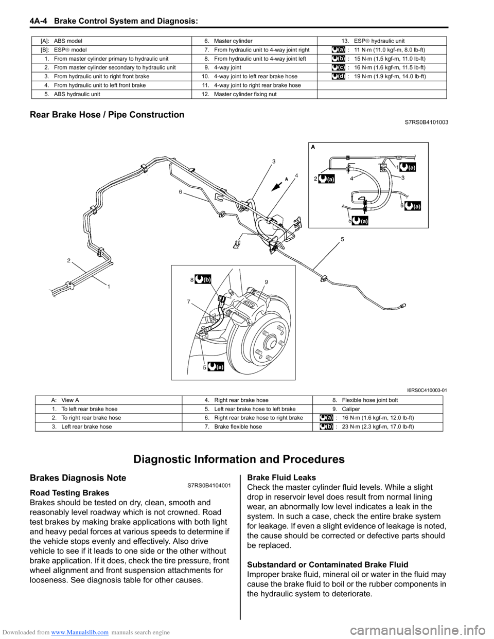
Rear Brake Hose / Pipe ConstructionS7RS0B4101003
Diagnostic Information and Procedures
Brakes Diagnosis NoteS7RS0B4104001
Road Testing Brakes
Brakes should be tested on dry, clean, smooth and
reasonably level roadway which is not crowned. Road
test brakes by making brake applications with both light
and heavy pedal forces at vari ous speeds to determine if
the vehicle stops evenly and effectively. Also drive
vehicle to see if it leads to one side or the other without
brake application. If it does, check the tire pressure, front
wheel alignment and front suspension attachments for
looseness. See diagnosis table for other causes. Brake Fluid Leaks
Check the master cylinder fl
uid levels. While a slight
drop in reservoir level does result from normal lining
wear, an abnormally low leve l indicates a leak in the
system. In such a case, chec k the entire brake system
for leakage. If even a slight ev idence of leakage is noted,
the cause should be corrected or defective parts should
be replaced.
Substandard or Contaminated Brake Fluid
Improper brake fluid, mineral oil or water in the fluid may
cause the brake fluid to boil or the rubber components in
the hydraulic system to deteriorate.
[A]: ABS model 6. Master cylinder13. ESP® hydraulic unit
[B]: ESP ® model 7. From hydraulic unit to 4-way joint right : 11 N⋅m (11.0 kgf-m, 8.0 lb-ft)
1. From master cylinder primary to hydraulic unit 8. From hydraulic unit to 4-way joint left: 15 N⋅m (1.5 kgf-m, 11.0 lb-ft)
2. From master cylinder secondary to hydraulic unit 9. 4-way joint: 16 N⋅m (1.6 kgf-m, 11.5 lb-ft)
3. From hydraulic unit to right front brake 10.4-way joint to left rear brake hose : 19 N⋅m (1.9 kgf-m, 14.0 lb-ft)
4. From hydraulic unit to left front brake 11. 4-way joint to right rear brake hose
5. ABS hydraulic unit 12. Master cylinder fixing nut
I6RS0C410003-01
A: View A4. Right rear brake hose8. Flexible hose joint bolt
1. To left rear brake hose 5. Left rear brake hose to left brake9. Caliper
2. To right rear brake hose 6. Right rear brake hose to right brake: 16 N⋅m (1.6 kgf-m, 12.0 lb-ft)
3. Left rear brake hose 7. Brake flexible hose: 23 N⋅m (2.3 kgf-m, 17.0 lb-ft)
Page 503 of 1496
Downloaded from www.Manualslib.com manuals search engine Brake Control System and Diagnosis: 4A-5
If deterioration of rubber is evident, disassemble all
hydraulic parts and wash with alcohol. Dry these parts
with compressed air before assembly to keep alcohol out
of the system. Replace all rubber parts in the system,
including hoses. Also, when working on the brake
mechanisms, check for fluid on the linings.
If excessive fluid is found, replace the pads. If master cylinder piston seals
are satisfactory, check for
leakage or excessive heat co nditions. If leakage is not
found, drain fluid, flush with brake fluid, refill and bleed
system.
The system must be flushed if there is any doubt as to
the grade of fluid in the system or if fluid has been used
which contained parts that have been subjected to
contaminated fluid.
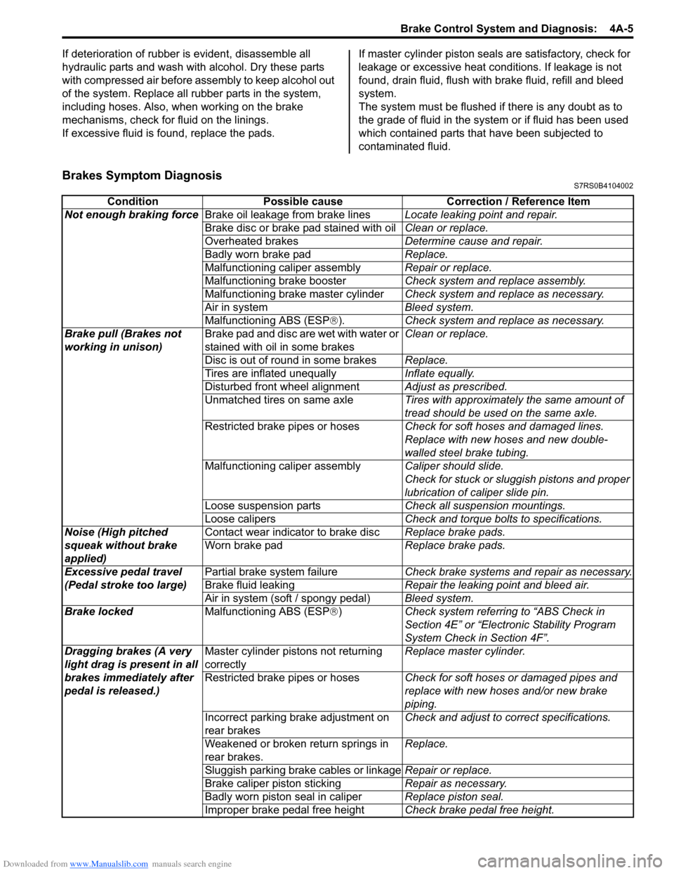
Brakes Symptom DiagnosisS7RS0B4104002
Condition Possible cause Correction / Reference Item
Not enough braking force Brake oil leakage from brake lines Locate leaking point and repair.
Brake disc or brake pad stained with oil Clean or replace.
Overheated brakes Determine cause and repair.
Badly worn brake pad Replace.
Malfunctioning caliper assembly Repair or replace.
Malfunctioning brake booster Check system and replace assembly.
Malfunctioning brake master cylinder Check system and replace as necessary.
Air in system Bleed system.
Malfunctioning ABS (ESP ®). Check system and replace as necessary.
Brake pull (Brakes not
working in unison) Brake pad and disc are wet with water or
stained with oil in some brakes Clean or replace.
Disc is out of round in some brakes Replace.
Tires are inflated unequally Inflate equally.
Disturbed front wheel alignment Adjust as prescribed.
Unmatched tires on same axle Tires with approximately the same amount of
tread should be used on the same axle.
Restricted brake pipes or hoses Check for soft hoses and damaged lines.
Replace with new hoses and new double-
walled steel brake tubing.
Malfunctioning caliper assembly Caliper should slide.
Check for stuck or sluggish pistons and proper
lubrication of caliper slide pin.
Loose suspension parts Check all suspension mountings.
Loose calipers Check and torque bolts to specifications.
Noise (High pitched
squeak without brake
applied) Contact wear indicator to brake disc
Replace brake pads.
Worn brake pad Replace brake pads.
Excessive pedal travel
(Pedal stroke too large) Partial brake system failure
Check brake systems and repair as necessary.
Brake fluid leaking Repair the leaking point and bleed air.
Air in system (soft / spongy pedal) Bleed system.
Brake locked Malfunctioning ABS (ESP®) Check system referri ng to “ABS Check in
Section 4E” or “Electronic Stability Program
System Check in Section 4F”.
Dragging brakes (A very
light drag is present in all
brakes immediately after
pedal is released.) Master cylinder pistons not returning
correctly
Replace master cylinder.
Restricted brake pipes or hoses Check for soft hoses or damaged pipes and
replace with new hoses and/or new brake
piping.
Incorrect parking brake adjustment on
rear brakes Check and adjust to correct specifications.
Weakened or broken return springs in
rear brakes. Replace.
Sluggish parking brake cables or linkage Repair or replace.
Brake caliper piston sticking Repair as necessary.
Badly worn piston seal in caliper Replace piston seal.
Improper brake pedal free height Check brake pedal free height.
Page 504 of 1496
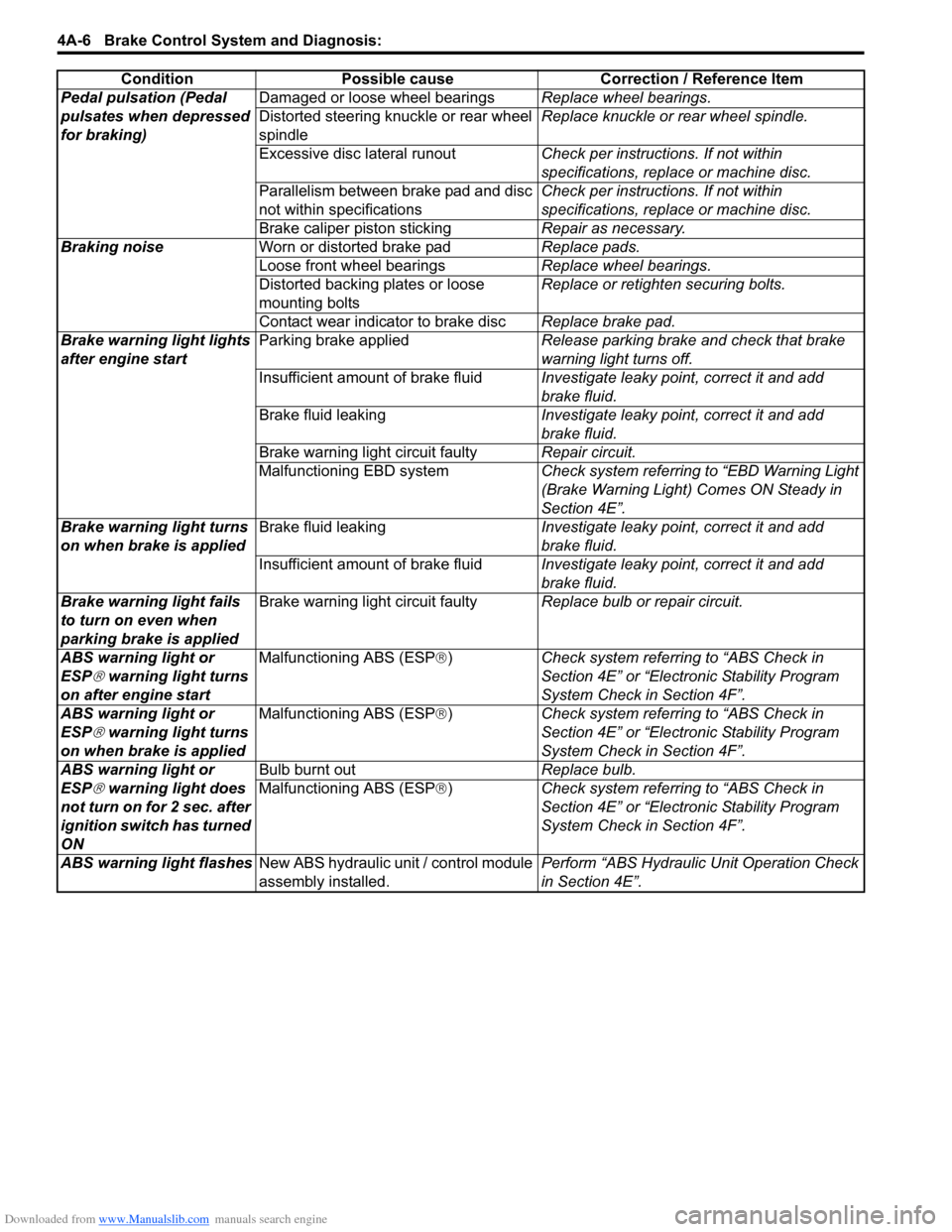
Downloaded from www.Manualslib.com manuals search engine 4A-6 Brake Control System and Diagnosis:
Pedal pulsation (Pedal
pulsates when depressed
for braking)Damaged or loose wheel bearings
Replace wheel bearings.
Distorted steering knuckle or rear wheel
spindle Replace knuckle or rear wheel spindle.
Excessive disc lateral runout Check per instructions. If not within
specifications, replace or machine disc.
Parallelism between brake pad and disc
not within specifications Check per instructions. If not within
specifications, replace or machine disc.
Brake caliper piston sticking Repair as necessary.
Braking noise Worn or distorted brake pad Replace pads.
Loose front wheel bearings Replace wheel bearings.
Distorted backing plates or loose
mounting bolts Replace or retighten securing bolts.
Contact wear indicator to brake disc Replace brake pad.
Brake warning light lights
after engine start Parking brake applied
Release parking brake and check that brake
warning light turns off.
Insufficient amount of brake fluid Investigate leaky point, correct it and add
brake fluid.
Brake fluid leaking Investigate leaky point, correct it and add
brake fluid.
Brake warning light circuit faulty Repair circuit.
Malfunctioning EBD system Check system referring to “EBD Warning Light
(Brake Warning Light) Comes ON Steady in
Section 4E”.
Brake warning light turns
on when brake is applied Brake fluid leaking
Investigate leaky point, correct it and add
brake fluid.
Insufficient amount of brake fluid Investigate leaky point, correct it and add
brake fluid.
Brake warning light fails
to turn on even when
parking brake is applied Brake warning light circuit faulty
Replace bulb or repair circuit.
ABS warning light or
ESP
® warning light turns
on after engine start Malfunctioning ABS (ESP
®) Check system referri ng to “ABS Check in
Section 4E” or “Electronic Stability Program
System Check in Section 4F”.
ABS warning light or
ESP
® warning light turns
on when brake is applied Malfunctioning ABS (ESP
®) Check system referri ng to “ABS Check in
Section 4E” or “Electronic Stability Program
System Check in Section 4F”.
ABS warning light or
ESP
® warning light does
not turn on for 2 sec. after
ignition switch has turned
ON Bulb burnt out
Replace bulb.
Malfunctioning ABS (ESP ®) Check system referri ng to “ABS Check in
Section 4E” or “Electronic Stability Program
System Check in Section 4F”.
ABS warning light flashes New ABS hydraulic unit / control module
assembly installed. Perform “ABS Hydraulic
Unit Operation Check
in Section 4E”.
Condition Possible cause Correction / Reference Item