radio antenna SUZUKI SWIFT 2007 2.G Service Workshop Manual
[x] Cancel search | Manufacturer: SUZUKI, Model Year: 2007, Model line: SWIFT, Model: SUZUKI SWIFT 2007 2.GPages: 1496, PDF Size: 34.44 MB
Page 65 of 1496
![SUZUKI SWIFT 2007 2.G Service Workshop Manual Downloaded from www.Manualslib.com manuals search engine Engine General Information and Diagnosis: 1A-15
Terminal Arrangement of ECM Coupler (Viewed from Harness Side)
[A]: Manual A/C model24. ABS / SUZUKI SWIFT 2007 2.G Service Workshop Manual Downloaded from www.Manualslib.com manuals search engine Engine General Information and Diagnosis: 1A-15
Terminal Arrangement of ECM Coupler (Viewed from Harness Side)
[A]: Manual A/C model24. ABS /](/img/20/7607/w960_7607-64.png)
Downloaded from www.Manualslib.com manuals search engine Engine General Information and Diagnosis: 1A-15
Terminal Arrangement of ECM Coupler (Viewed from Harness Side)
[A]: Manual A/C model24. ABS / ESP® control module 49. Radiator cooling fan motor
[B]: Auto A/C model 25. TCM 50. “RDTR FAN” fuse
1. ECM 26. To other control module connected CAN 51. A/C compressor relay
2. APP sensor assembly 27. Generator 52. Magnet clutch of compressor (A/C model)
3. Shield wire 28. Electric load current sensor (if equipped) 53. “A/C CPRSR” fuse
4. CMP sensor 29. Brake light 54. Ignition coil assembly (for No.1 and No.4 spark
plugs)
5. CKP sensor 30. Brake light switch 55. Ignition coil assembly (for No.2 and No.3 spark
plugs)
6. MAF and IAT sensor 31. Diagnosis connector (Hong Kong model) 56. P/S control module
7. MAP sensor 32. Throttle actuator control relay 57. “RADIO” fuse
8. ECT sensor 33. “THR MOT” fuse 58. Main relay
9. A/C refrigerant pressure sensor 34. Throttle throttle body assembly 59. “IG COIL” fuse
10. A/C evaporator outlet air temp. sensor (Manual A/C model) 35. Throttle actuator
60. Ignition switch
11. HO2S-1 36. TP sensor 61. “IG ACC” fuse
12. HO2S-2 37. Injector No.1 62. “FI” fuse
13. Knock sensor 38. Injector No.2 63. Starting motor control relay
14. Blower motor relay 39. Injector No.3 64. “ST SIG” fuse
15. Blower motor 40. Injector No.4 65. “ST MOT” fuse
16. Blower motor resistor 41. EVAP canister purge valve66. Transmission range switch (A/T model) or CPP
switch (Hong Kong model with M/T)
17. Blower speed selector 42. EGR valve 67. Starting motor
18. A/C switch 43. Oil control valve (Camshaft position
control) (VVT model) 68. Immobilizer coil antenna
19. Blower motor controller 44. Fuel pump relay 69. Main fuse box
20. HVAC control module 45. Fuel pump 70. Battery
21. Data link connector (DLC) 46. Radiator cooling fan motor relay No.1 71. Barometric pressure sensor
22. To other control module connected with DLC 47. Radiator cooling fan motor relay No.2
72. Engine ground
23. BCM 48. Radiator cooling fan motor relay No.3 73. Body ground
E23 C37
34
1819
567
1011
17
20
47 46
495051
2122
52 16
25 9
24
14
29
55
57 54 53
59
60 58 2
262728
15
30
56 4832 31
34353637
40
42 39 38
44
45 43 41 331
1213
238
34
1819
567
1011
17
20
47 46
495051
2122
52 16
25 9
24
14
29
55
57 54 53
59
60 58 2
262728
15
30
56 4832 31
34353637
40
42 39 38
44
45 43 41 331
1213
238
I4RS0A110008-01
Page 1243 of 1496
Downloaded from www.Manualslib.com manuals search engine Wiring Systems: 9A-72
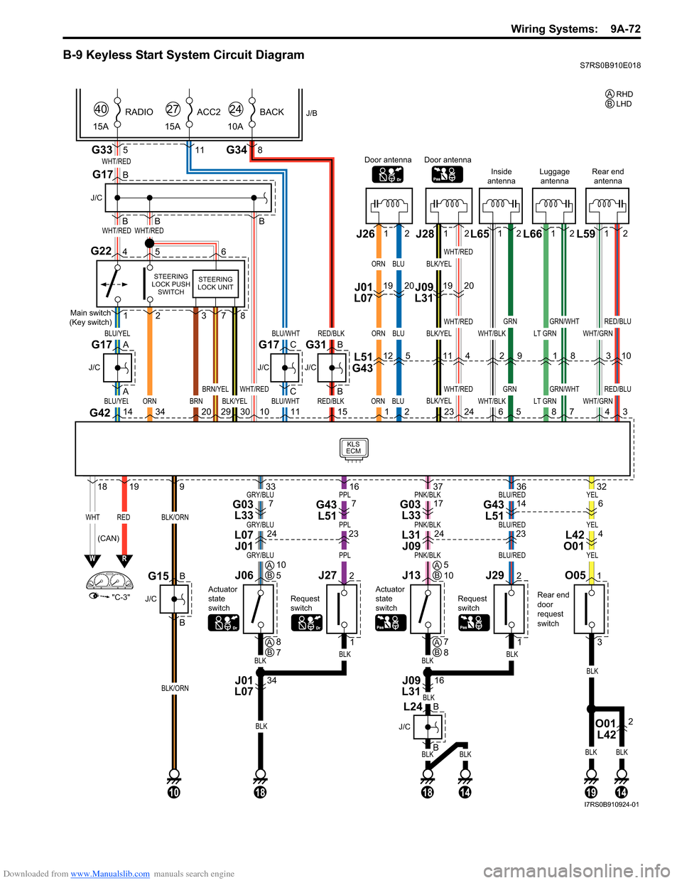
B-9 Keyless Start System Circuit DiagramS7RS0B910E018
BLKBLK
BLK
BLKBLK
YELBLU/REDPNK/BLKPPLGRY/BLU
YELBLU/REDPNK/BLKPPLGRY/BLU
YELBLU/REDPNK/BLKPPLGRY/BLU
G33
KLS
ECM
WHT/RED
WHT/REDWHT/RED
BLU/YEL
WHTRED
ORN
BLU/YEL
"C-3"
WR
G42143420
1819
BLK/ORN
BLK/ORN
9
5
J/B
15A RADIO
40
G348
10A
BACK
24
11
15A
ACC2
27
B
B
B
J/C
G17
B
A
A
J/C
BLU/WHT
BLU/WHT
C
C
J/C
G17
Main switch
(Key switch)
STEERING
LOCK PUSH SWITCH
G22456
1
O051
3
2
BRN29
BRN/YEL
301011RED/BLK
RED/BLK
B
B
J/C
Rear end
door
request
switch
G31
15ORN
ORN
ORN
1BLK/YEL
WHT/RED
378
STEERING
LOCK UNIT
Door antenna
L51
G4312
J01
L07 J261912
BLU
BLU
BLU
2
5
20
WHT/BLK
WHT/BLK6
Inside
antenna
2
12
GRN
GRN
5
9
LT GRN
LT GRN8
Luggage antenna
1
12
GRN/WHT
GRN/WHT
7
8
BLK/YEL
BLK/YEL
BLK/YEL
23
Door antenna
11
J09
L31 J28 L65 L66
WHT/GRN
WHT/GRN4
Rear end
antenna
3
12
RED/BLU
RED/BLU
3
10
L59
1912
WHT/RED
WHT/RED
WHT/RED
24
4
20
G17
B
B
J/C
G15
10
BLK
BLKBLK
32
J292
1
Request
switch
36
1914
J13
Actuator
state
switch
O01 L422
16
BLK
37
1814
J09
L31
J272
1
Request
switch
16
J06
Actuator
state
switch
34
BLK
BLK
33
18
J01
L07
(CAN) RHD
A
LHD
B
AB10
5AB5
10
AB8
7AB7
8
614G43
L5117G03 L337G43 L517G03 L33
423242324L42
O01
L31
J09
L07
J01
B
J/C
B
L24
I7RS0B910924-01
Page 1272 of 1496
Downloaded from www.Manualslib.com manuals search engine 9A-101 Wiring Systems:
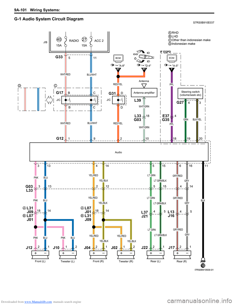
G-1 Audio System Circuit DiagramS7RS0B910E037
PPL
PPL
G335
GRY
18141814L37J21
G03 L333 13 2
515 14
4 5
4
5
11
21 1
2 2
1 1
2 2
1 2
1
3
13 4
14 5
15 6
16 11
RY"D-4"RY
WHT/RED
G121
J/C
G17
WHT/RED
J/B15ARADIO
40
RED/YEL
J/C
G31
BCM
"A-8"
Antenna amplifier
WHT/GRN
L39
L33
G0318E37
G354
WHT/GRN
BLU/WHT
BLU/WHT
15A ACC 2
27
BLK
10
Tweeter (L)Front (L)
PNKBLU
J12
J10
Tweeter (R)Front (R)
J04J02
YEL/BLK
YEL/RED
Rear (R)Rear (L)
LT GRN
LT GRN/BLKPNKBLUPNKBLUYEL/BLK
YEL/RED
YEL/BLK
YEL/REDLT GRN
LT GRN/BLK
GRY/RED
GRY
GRY/RED
PNKBLUYEL/BLK
YEL/REDLT GRN
LT GRN/BLKGRY
GRY/RED
12
Audio
RED/YEL
921 0
J22J17
B
B C
C D
DSteering switch
(volume/seek etc)
G27
GRN
1920
BLK/YEL
4 3
L13
J16
4
P
ECM
"A-5"
18
RHD
LHD
Other than indonesian make
Indonesian make
ABC
DC
D
Antenna
L31
J09
L07 J01A
B
L07 J01
L31 J09A
B
IF EQPD
I7RS0B910938-01
Page 1301 of 1496
Downloaded from www.Manualslib.com manuals search engine Instrumentation / Driver Info. / Horn: 9C-6
Component Location
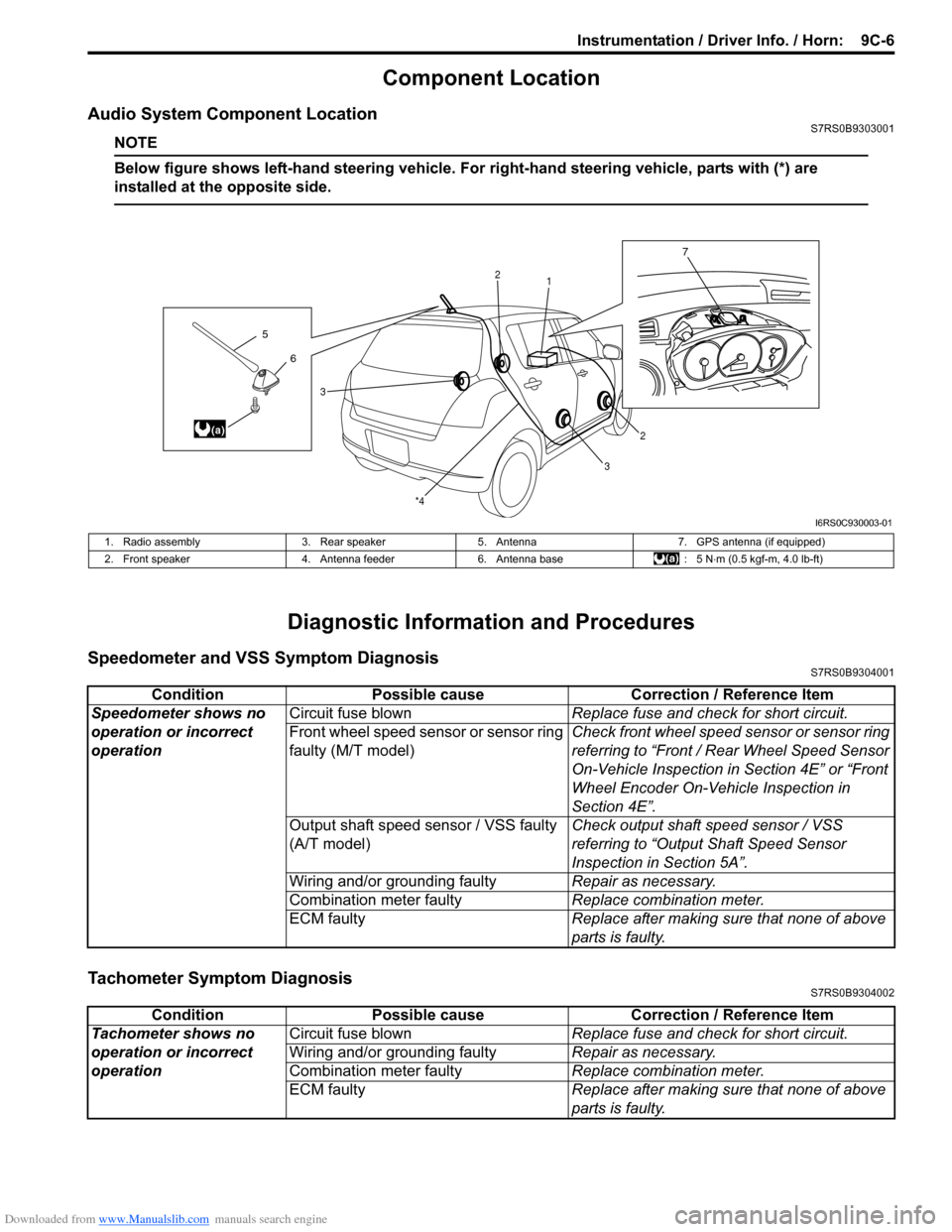
Audio System Component LocationS7RS0B9303001
NOTE
Below figure shows left-hand steering vehicle. For right-hand steering vehicle, parts with (*) are
installed at the opposite side.
Diagnostic Information and Procedures
Speedometer and VSS Symptom DiagnosisS7RS0B9304001
Tachometer Symptom DiagnosisS7RS0B9304002
6
5
(a)
7
1
2
2
3
3
*4
I6RS0C930003-01
1. Radio assembly
3. Rear speaker5. Antenna 7. GPS antenna (if equipped)
2. Front speaker 4. Antenna feeder6. Antenna base : 5 N⋅m (0.5 kgf-m, 4.0 lb-ft)
Condition Possible cause Correction / Reference Item
Speedometer shows no
operation or incorrect
operation Circuit fuse blown
Replace fuse and check for short circuit.
Front wheel speed sensor or sensor ring
faulty (M/T model) Check front wheel speed sensor or sensor ring
referring to “Front / Rear Wheel Speed Sensor
On-Vehicle Inspection in
Section 4E” or “Front
Wheel Encoder On-Vehicle Inspection in
Section 4E”.
Output shaft speed sensor / VSS faulty
(A/T model) Check output shaft
speed sensor / VSS
referring to “Output Shaft Speed Sensor
Inspection in Section 5A”.
Wiring and/or grounding faulty Repair as necessary.
Combination meter faulty Replace combination meter.
ECM faulty Replace after making sure that none of above
parts is faulty.
ConditionPossible cause Correction / Reference Item
Tachometer shows no
operation or incorrect
operation Circuit fuse blown
Replace fuse and check for short circuit.
Wiring and/or grounding faulty Repair as necessary.
Combination meter faulty Replace combination meter.
ECM faulty Replace after making sure that none of above
parts is faulty.
Page 1307 of 1496
Downloaded from www.Manualslib.com manuals search engine Instrumentation / Driver Info. / Horn: 9C-12
Clock Symptom Diagnosis (If Equipped)S7RS0B9304016
Audio System Symptom Diagnosis (If Equipped)S7RS0B9304017
Radio
NOTE
Electronic part / system with undiagnosed pr oblem may cause electromagnetic interference.
Electromagnetic interference condition may have poor radio reception. To test for presence of
electromagnetic interference in part / system, perform the following procedures.
1. Turn ignition switch to OFF.
2. Systematically disconnect the electronic part / system connector(s) one at a time.
3. Turn ignition switch to ON.
4. Check any improvement in radio reception.
Display of fuel
consumption does not
change at “– – – l / 100 km
(km/l, MPG)” Vehicle is not running (instantaneous
fuel consumption mode)
—
Fuel consumption was reset (average
fuel consumption mo de, if equipped)Vehicle runs for a while.
Vehicle speed signal faulty Check ECM for DTC referring to “DTC Check
in Section 1A”.
Wiring and/or grounding faulty Repair as necessary.
ECM faulty Check input and output signal of ECM referring
to “Inspection of ECM and Its Circuits in
Section 1A”.
Information display unit faulty Replace unit.
BCM faulty Replace after making sure that none of above
parts is faulty.
Condition Possible cause Correction / Reference Item
Condition
Possible cause Correction / Reference Item
No displaying of clock Circuit fuse Blown Replace fuse and check for short circuit.
Wiring and/or grounding faulty Repair as necessary.
Clock unit faulty Replace unit.
ConditionPossible cause Correction / Reference Item
Poor radio reception Out of service area (Poor location) —
Antenna faulty Replace antenna.
Electrical part / system faulty Repair or replace electrical part / system
referring to after-mentioned NOTE.
Wiring and/or grounding faulty Repair as necessary.
Radio assembly faulty Replace radio assembly.
Radio does not operate
and speaker does not
sound Circuit fuse(s) blown
Replace fuse(s) and check for short circuit.
Wiring and/or grounding faulty Repair as necessary.
Radio assembly faulty Replace radio assembly.
Radio does not operate,
but speaker sound Wiring and/or grounding faulty
Repair as necessary.
Radio assembly faulty Replace radio assembly.
Radio is operative, but all
speakers does not sound Wiring and/or grounding faulty
Repair as necessary.
Radio assembly faulty Replace radio assembly.
Individual speaker is
noisy or inoperative Wiring and/or grounding faulty
Repair as necessary.
Speaker faulty Replace speaker.
Radio assembly faulty Replace radio assembly.
Sound quality is poor Out of service area (Poor location) —
Speaker installed incorrectly Install correctly.
Wiring and/or grounding faulty Repair as necessary.
Speaker faulty Replace speaker.
Radio assembly faulty Replace radio assembly.
Page 1445 of 1496
Downloaded from www.Manualslib.com manuals search engine Immobilizer Control System: 10C-2
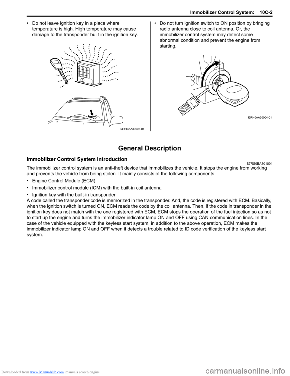
• Do not leave ignition key in a place where
temperature is high. High temperature may cause
damage to the transponder built in the ignition key. • Do not turn ignition switch to ON position by bringing
radio antenna close to coil antenna. Or, the
immobilizer control syst em may detect some
abnormal condition and prevent the engine from
starting.
General Description
Immobilizer Control System IntroductionS7RS0BA301001
The immobilizer control system is an anti-theft device that immobilizes the vehicle. It stops the engine from working
and prevents the vehicle from being stolen. It mainly consists of the following components.
• Engine Control Module (ECM)
• Immobilizer control module (ICM) with the built-in coil antenna
• Ignition key with the built-in transponder
A code called the transponder code is memorized in the tran sponder. And, the code is registered with ECM. Basically,
when the ignition switch is turned ON, ECM reads the code by the coil antenna. Then, if the code in transponder in the
ignition key does not match with the one registered with ECM, ECM stops the operati on of the fuel injection so as not
to start up the engine and turns the immobilizer indi cator lamp ON and OFF using CA N communication lines. In the
case of the vehicle equipped with the keyless start system , in addition to the above operation, ECM makes the
immobilizer indicator lamp ON and OFF when it detects a trouble related to ID code verification of the keyless start
system.
I3RH0AA30003-01
I3RH0AA30004-01
Page 1466 of 1496
Downloaded from www.Manualslib.com manuals search engine 10E-4 Keyless Start System:
Door Lock Function of Keyless Start SystemS7RS0BA501004
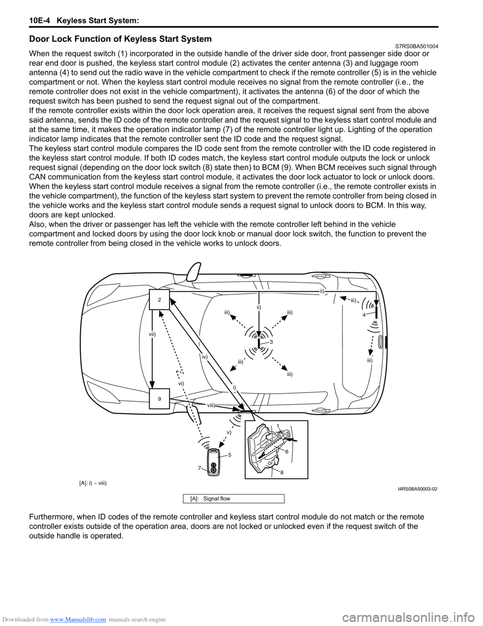
When the request switch (1) incorporated in the outside handle of the driver side door, front passenger side door or
rear end door is pushed, the keyless start control modul e (2) activates the center antenna (3) and luggage room
antenna (4) to send out the radio wave in the vehicle compartm ent to check if the remote controller (5) is in the vehicle
compartment or not. When the keyless start control module receives no signal from the remote controller (i.e., the
remote controller does not exist in the vehicle compartment) , it activates the antenna (6) of the door of which the
request switch has been pushed to send the request signal out of the compartment.
If the remote controller exists within the door lock operati on area, it receives the request signal sent from the above
said antenna, sends the ID code of the remote controller and the request signal to the keyless start control module and
at the same time, it makes the operatio n indicator lamp (7) of the remote controller light up. Lighting of the operation
indicator lamp indicates that the remote controller sent the ID code and the request signal.
The keyless start control module compares the ID code sent from the remote controller with the ID code registered in
the keyless start control module. If both ID codes match, the keyless start control module outputs the lock or unlock
request signal (depending on the door lock switch (8) stat e then) to BCM (9). When BCM receives such signal through
CAN communication from the keyless start control module, it activates the door lock actuator to lock or unlock doors.
When the keyless start control module receiv es a signal from the remote controller (i.e., the remote controller exists in
the vehicle compartment), the function of the keyless start system to prevent the remote controller from being closed in
the vehicle works and the keyless start control module sends a request signal to unlock doors to BCM. In this way,
doors are kept unlocked.
Also, when the driver or passenger has left the vehicl e with the remote controller left behind in the vehicle
compartment and locked doors by using the door lock knob or manual door lock switch, the function to prevent the
remote controller from being closed in the vehicle works to unlock doors.
Furthermore, when ID codes of the remote controller and keyless start control module do not match or the remote
controller exists outside of the operation area, doors are not locked or unlocked even if the request switch of the
outside handle is operated.
9 2
vi)
v)
vii) iv)
i) ii)
iii)
iii)iii)
ii)
iii)
iii)
iii)
3
5
8
6
1 4
7
[A]: i) ~ viii)
viii)
I4RS0BA50003-02
[A]: Signal flow
Page 1467 of 1496
Downloaded from www.Manualslib.com manuals search engine Keyless Start System: 10E-5
Operation Area of Remote ControllerS7RS0BA501005
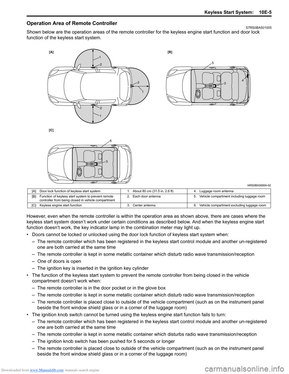
Shown below are the operation areas of the remote controller for the keyless engine start function and door lock
function of the keyless start system.
However, even when the remote controller is within the operation area as shown above, there are cases where the
keyless start system doesn’t work under certain conditi ons as described below. And when the keyless engine start
function doesn’t work, the key indicator la mp in the combination meter may light up.
• Doors cannot be locked or unlocked using the doo r lock function of keyless start system when:
– The remote controller which has been registered in the keyless start control module and another un-registered one are both carried at the same time
– The remote controller is kept in some metallic co ntainer which disturb radio wave transmission/reception
– One of doors is open
– The ignition key is inserted in the ignition key cylinder
• The function of the keyless start system to prevent the remote controller from being closed in the vehicle
compartment doesn’t work when:
– The remote controller is in the door pocket or in the glove box
– The remote controller is kept in some metallic co ntainer which disturb radio wave transmission/reception
– The remote controller is placed close to outside of the vehicle compartment (such as on the instrument panel beside the front window shield glass or in a corner of the luggage room)
• The ignition knob switch cannot be turned usin g the keyless engine start function fails to turn:
– The remote controller which has been registered in the keyless start control module and another un-registered one are both carried at the same time
– The remote controller is kept in some metallic cont ainer which disturbs radio wave transmission/reception
– The ignition knob switch has been pushed for 5 seconds or longer
– The remote controller is placed close to outside of the vehicle compartment (such as on the instrument panel beside the front window shield glass or in a corner of the luggage room)
[A] [B]
[C]
1
1
1
25
6
3
3 4
2
2
I4RS0BA50004-02
[A]: Door lock function of keyless start system 1. About 80 cm (31.5 in, 2.6 ft)4. Luggage room antenna
[B]: Function of keyless start system to prevent remote controller from being closed in vehicle compartment 2. Each door antenna
5. Vehicle compartment including luggage room
[C]: Keyless engine start function 3. Center antenna6. Vehicle compartment excluding luggage room