Connection SUZUKI SWIFT 2008 2.G Service Owners Manual
[x] Cancel search | Manufacturer: SUZUKI, Model Year: 2008, Model line: SWIFT, Model: SUZUKI SWIFT 2008 2.GPages: 1496, PDF Size: 34.44 MB
Page 220 of 1496

Downloaded from www.Manualslib.com manuals search engine 1A-170 Engine General Information and Diagnosis:
4Wire harness check
1) Disconnect connectors from ECM with ignition switch
turned OFF.
2) Measure resistance between “C37-43” terminal of ECM connector and engine ground.
Is resistance infinity? Go to Step 5. “RED” wire is shorted to
other circuit.
5 Wire harness check
1) Measure voltage between “C37-43” terminal of ECM
connector and engine ground with ignition switch turned
ON.
Is voltage 0 V? Substitute a known-
good ECM and recheck.
“RED” wire is shorted to
other circuit.
6 Wire harness check
1) Measure voltage between “GRN” wire terminal of electric
throttle body connector and engine ground, between
“WHT” wire terminal of electric throttle body connector
and engine ground with ignition switch turned ON.
Is each voltage 4 – 6 V? Go to Step 9. Go to Step 7.
7 Wire harness check
1) Turn OFF ignition switch.
2) Disconnect connectors from ECM.
3) Check for proper connection of ECM connector at “C37-
54” and “C37-40” terminals.
4) If OK, measure voltage between “C37-54” terminal of ECM connector and engine ground, between “C37-40”
terminal of ECM connector and engine ground.
Is each voltage 0 V? Go to Step 8. “GRN” wire or “WHT”
wire is shorted to other
circuit.
8 Wire harness check
1) Measure resistance between “GRN” wire terminal of
electric throttle body connector and engine ground,
between “WHT” wire terminal of electric throttle body
connector and engine ground with ignition switch turned
OFF.
Is each resistance infinity? Substitute a known-
good ECM and recheck.
“GRN” wire or “WHT”
wire is shorted to other
circuit.
9 Electric throttle body check
1) Check TP sensor referring to “Throttle Position Sensor
Performance Check” under “Electric Throttle Body
Assembly On-Vehicle Inspection in Section 1C”.
Is each output voltage within specified value? Substitute a known-
good ECM and recheck.
Replace electric throttle
body.
Step Action Yes No
Page 222 of 1496
Downloaded from www.Manualslib.com manuals search engine 1A-172 Engine General Information and Diagnosis:
DTC Troubleshooting
NOTE
• When measuring circuit voltage, resistance and/or pulse signal at ECM connector, connect the
special tool to ECM and/or the ECM connectors re ferring to “Inspection of ECM and Its Circuits”.
• Upon completion of inspection and repair work, perform “DTC Confirmation Procedure” and confirm that the trouble has been corrected.
Step Action YesNo
1 Was “Engine and Emission Control System Check”
performed? Go to Step 2.
Go to “Engine and
Emission Control
System Check”.
2 APP sensor and its circuit check
1) Connect scan tool to DLC with ignition switch turned
OFF.
2) Turn ON ignition switch.
3) Check each voltage of “APP Sensor 1 Volt” and “APP Sensor 2 Volt” displayed on scan tool when accelerator
pedal is idle position and fully depressed.
Is displayed each APP sensor value as described voltage in
“Scan Tool Data”? Intermittent trouble.
Check for intermittent
referring to “Intermittent
and Poor Connection
Inspection in Section
00”.
Go to Step 3.
3 ECM voltage check
1) Disconnect connector from APP sensor with ignition
switch turned OFF.
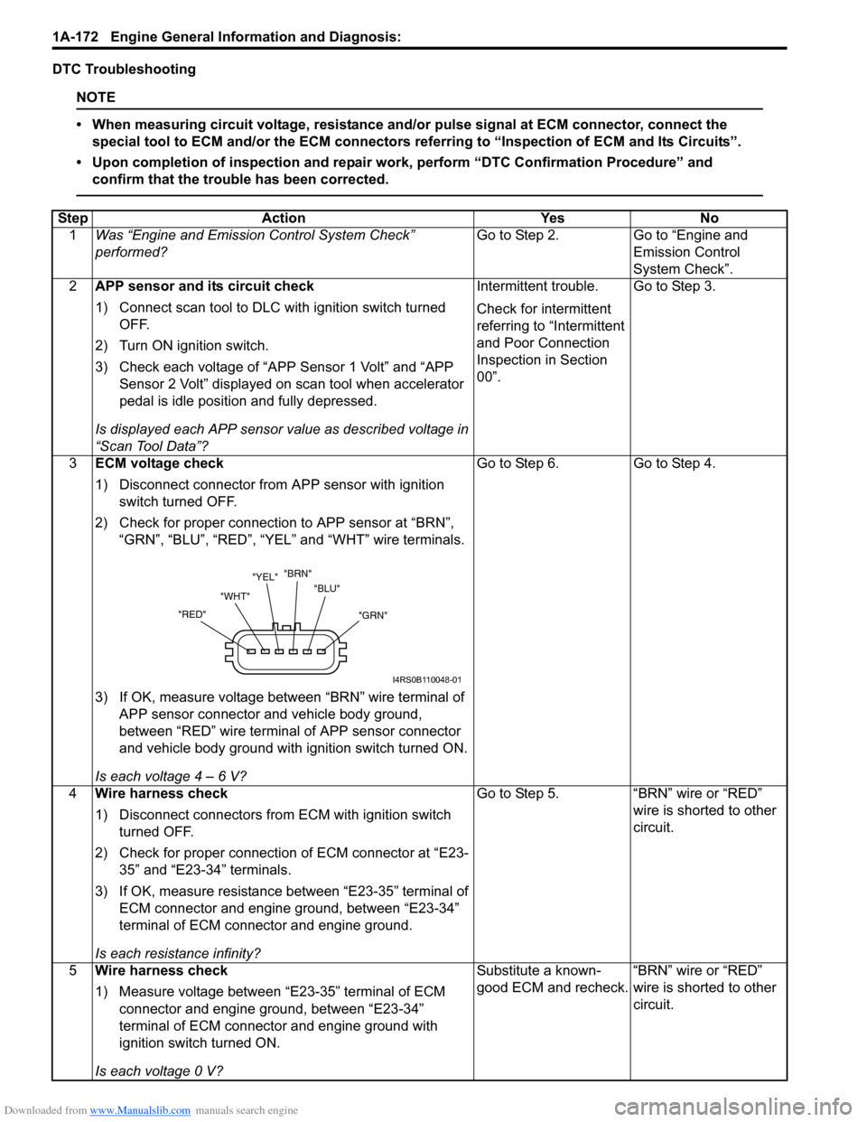
2) Check for proper connection to APP sensor at “BRN”, “GRN”, “BLU”, “RED”, “YEL” and “WHT” wire terminals.
3) If OK, measure voltage between “BRN” wire terminal of APP sensor connector and vehicle body ground,
between “RED” wire terminal of APP sensor connector
and vehicle body ground with ignition switch turned ON.
Is each voltage 4 – 6 V? Go to Step 6.
Go to Step 4.
4 Wire harness check
1) Disconnect connectors from ECM with ignition switch
turned OFF.
2) Check for proper connection of ECM connector at “E23- 35” and “E23-34” terminals.
3) If OK, measure resistance between “E23-35” terminal of ECM connector and engine ground, between “E23-34”
terminal of ECM connector and engine ground.
Is each resistance infinity? Go to Step 5.
“BRN” wire or “RED”
wire is shorted to other
circuit.
5 Wire harness check
1) Measure voltage between “E23-35” terminal of ECM
connector and engine ground, between “E23-34”
terminal of ECM connector and engine ground with
ignition switch turned ON.
Is each voltage 0 V? Substitute a known-
good ECM and recheck.
“BRN” wire or “RED”
wire is shorted to other
circuit.
"GRN"
"BLU"
"BRN"
"YEL"
"WHT"
"RED"
I4RS0B110048-01
Page 223 of 1496
Downloaded from www.Manualslib.com manuals search engine Engine General Information and Diagnosis: 1A-173
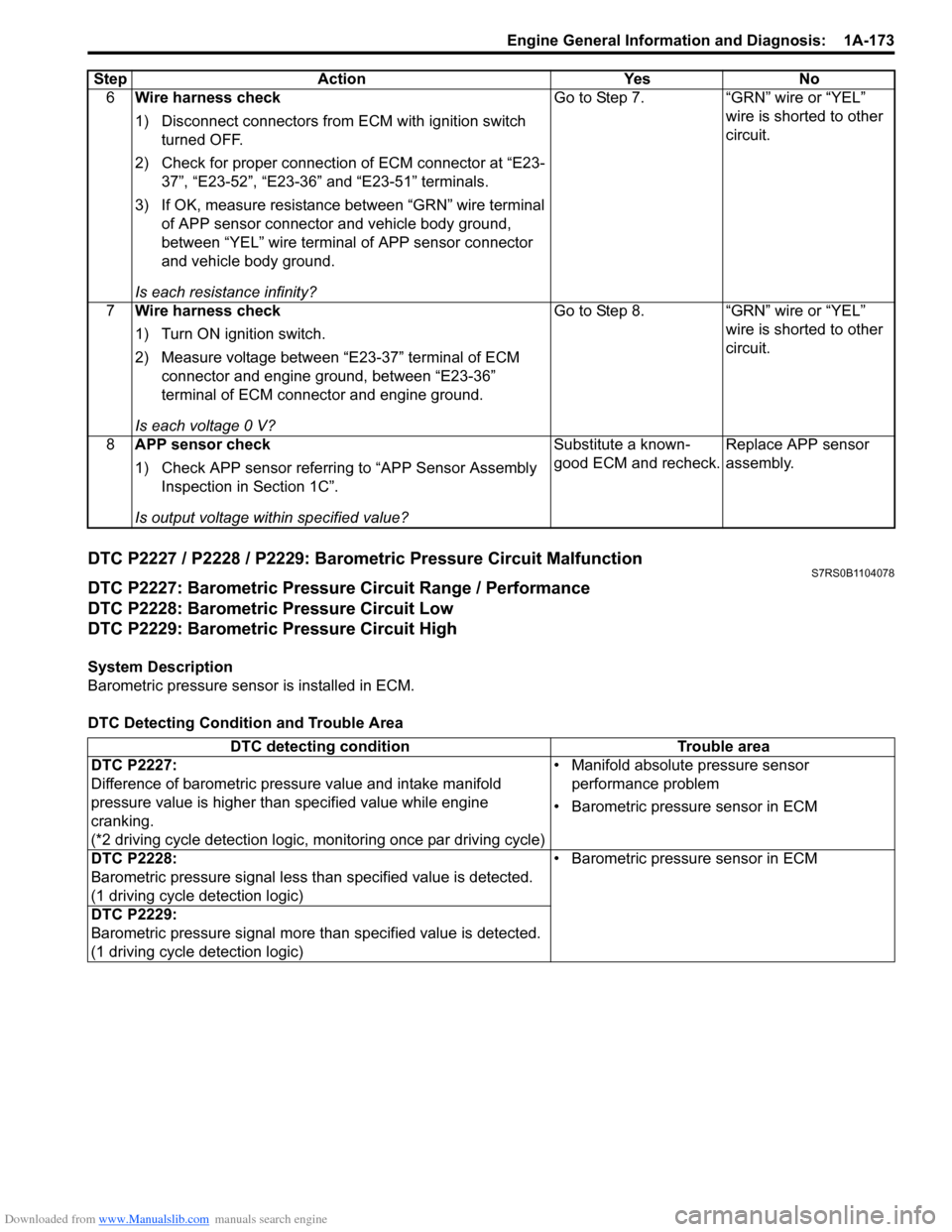
DTC P2227 / P2228 / P2229: Barometric Pressure Circuit MalfunctionS7RS0B1104078
DTC P2227: Barometric Pressure Circuit Range / Performance
DTC P2228: Barometric Pressure Circuit Low
DTC P2229: Barometric Pressure Circuit High
System Description
Barometric pressure sensor is installed in ECM.
DTC Detecting Condition and Trouble Area6
Wire harness check
1) Disconnect connectors from ECM with ignition switch
turned OFF.
2) Check for proper connection of ECM connector at “E23- 37”, “E23-52”, “E23-36” and “E23-51” terminals.
3) If OK, measure resistance between “GRN” wire terminal of APP sensor connector and vehicle body ground,
between “YEL” wire terminal of APP sensor connector
and vehicle body ground.
Is each resistance infinity? Go to Step 7. “GRN” wire or “YEL”
wire is shorted to other
circuit.
7 Wire harness check
1) Turn ON ignition switch.
2) Measure voltage between “E23-37” terminal of ECM
connector and engine ground, between “E23-36”
terminal of ECM connector and engine ground.
Is each voltage 0 V? Go to Step 8. “GRN” wire or “YEL”
wire is shorted to other
circuit.
8 APP sensor check
1) Check APP sensor referring to “APP Sensor Assembly
Inspection in Section 1C”.
Is output voltage within specified value? Substitute a known-
good ECM and recheck.
Replace APP sensor
assembly.
Step Action Yes No
DTC detecting condition
Trouble area
DTC P2227:
Difference of barometric pressure value and intake manifold
pressure value is higher than specified value while engine
cranking.
(*2 driving cycle detection logic, monitoring once par driving cycle) • Manifold absolute pressure sensor
performance problem
• Barometric pressure sensor in ECM
DTC P2228:
Barometric pressure signal less than specified value is detected.
(1 driving cycle detection logic) • Barometric pressure sensor in ECM
DTC P2229:
Barometric pressure signal more than specified value is detected.
(1 driving cycle detection logic)
Page 245 of 1496
Downloaded from www.Manualslib.com manuals search engine Engine General Information and Diagnosis: 1A-195
Circuit Description
When the ignition switch is turned ON, the main relay turns ON (the contact point closes) and the main power is
supplied to ECM.
Troubleshooting
NOTE
When measuring circuit voltage, resistance and/or pulse signal at ECM connector, connect the special
tool to ECM and/or the ECM connectors referri ng to “Inspection of ECM and Its Circuits”.
StepAction YesNo
1 Circuit fuse check
1) Disconnect connectors from ECM with ignition switch
turned OFF.
2) Check for proper connection to ECM connector at “E23- 2”, “E23-29”, “E23-60”, “E23-1”, “E23-16”, “E23-31”,
“C37-58”, “C37-15” and “C37-30” terminals.
3) If OK, check “RADIO” fuse and “IG COIL” fuse for blowing.
Are “RADIO” fuse and “IG COIL” fuse in good condition? Go to Step 2.
Replace fuse (s) and
check for short in
circuits connected to
fuse(s).
2 Power supply circuit check
1) Measure voltage between “E23-2” terminal of ECM
connector and body ground.
Is voltage 10 – 14 V? Go to Step 3.
“WHT/RED” or “WHT”
wire is open circuit.
3 Ignition signal check
1) Turn ignition switch to ON position.
2) Measure voltage between “E23-29” terminal of ECM
connector and body ground.
Is voltage 10 – 14 V? Go to Step 4.
“BLK/WHT” or “GRN”
wire is open circuit.
4 Main relay circuit check
1) Turn ignition switch to OFF position.
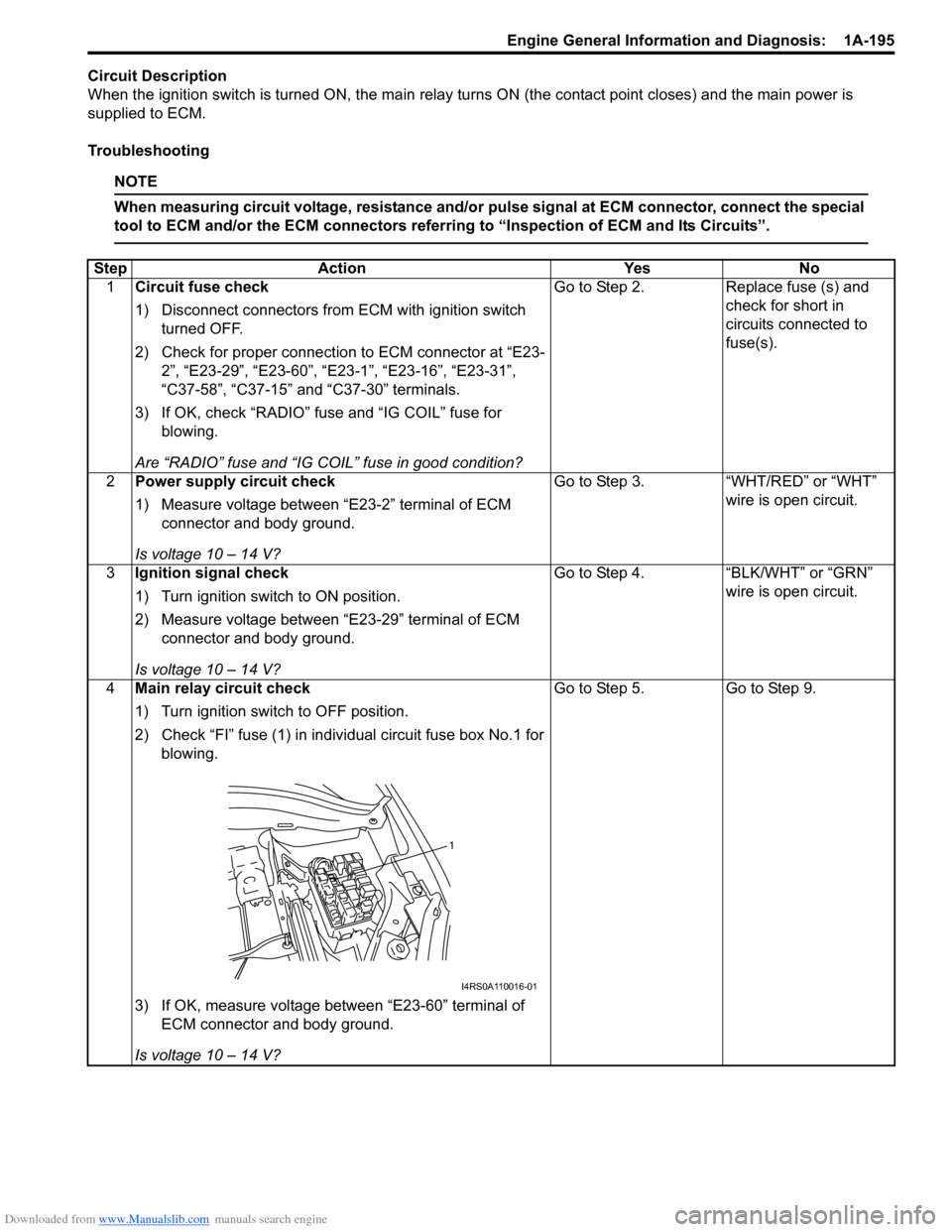
2) Check “FI” fuse (1) in indivi dual circuit fuse box No.1 for
blowing.
3) If OK, measure voltage between “E23-60” terminal of ECM connector and body ground.
Is voltage 10 – 14 V? Go to Step 5.
Go to Step 9.
1
I4RS0A110016-01
Page 246 of 1496
Downloaded from www.Manualslib.com manuals search engine 1A-196 Engine General Information and Diagnosis:
5Main relay circuit check
1) Connect connectors to ECM with ignition switch turned
OFF.
2) Turn ignition switch to ON position.
3) Measure voltage between “E23-60” terminal of ECM connector and body ground.
Is voltage 0 – 1 V? Go to Step 7. Go to Step 6.
6 ECM ground circuit check
1) Turn ignition switch to OFF position.
2) Disconnect connectors from ECM.
3) Measure resistance between each “E23-31”, “C37-58”,
“C37-15” and “C37-30” terminals of ECM connector and
body ground.
Is resistance 1
Ω or less? Substitute a known-
good ECM and recheck.
“BLK/ORN” or “BLK”
wire is open or high
resistance circuit.
7 Main relay circuit check
1) Disconnect connectors from ECM with ignition switch
turned OFF.
2) Using service wire, ground “E23-60” terminal of ECM connector and measure voltage between each “E23-1”
and “E23-16” terminals of ECM connector and body
ground.
Is voltage 10 – 14 V? Go to Step 11. Go to Step 8.
8 Main relay circuit check
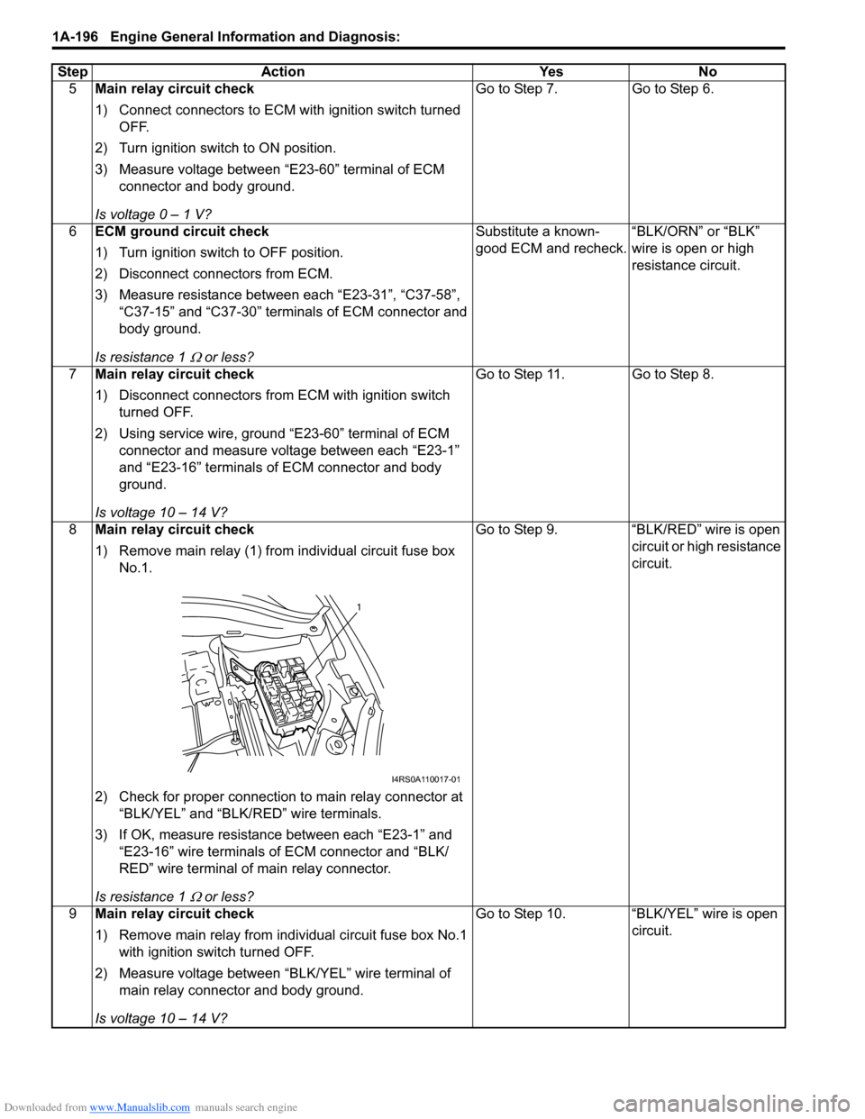
1) Remove main relay (1) from individual circuit fuse box
No.1.
2) Check for proper connection to main relay connector at “BLK/YEL” and “BLK/RED” wire terminals.
3) If OK, measure resistance between each “E23-1” and “E23-16” wire terminals of ECM connector and “BLK/
RED” wire terminal of main relay connector.
Is resistance 1
Ω or less? Go to Step 9. “BLK/RED” wire is open
circuit or high resistance
circuit.
9 Main relay circuit check
1) Remove main relay from individual circuit fuse box No.1
with ignition swit ch turned OFF.
2) Measure voltage between “BLK/YEL” wire terminal of main relay connector and body ground.
Is voltage 10 – 14 V? Go to Step 10. “BLK/YEL” wire is open
circuit.
Step Action Yes No
1
I4RS0A110017-01
Page 249 of 1496
Downloaded from www.Manualslib.com manuals search engine Engine General Information and Diagnosis: 1A-199
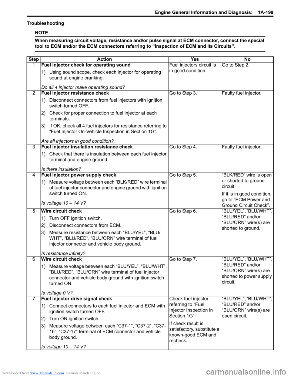
Troubleshooting
NOTE
When measuring circuit voltage, resistance and/or pulse signal at ECM connector, connect the special
tool to ECM and/or the ECM connectors referri ng to “Inspection of ECM and Its Circuits”.
StepAction YesNo
1 Fuel injector check for operating sound
1) Using sound scope, check each injector for operating
sound at engine cranking.
Do all 4 injector ma ke operating sound? Fuel injectors circuit is
in good condition.
Go to Step 2.
2 Fuel injector resistance check
1) Disconnect connectors from fuel injectors with ignition
switch turned OFF.
2) Check for proper connection to fuel injector at each terminals.
3) If OK, check all 4 fuel inject ors for resistance referring to
“Fuel Injector On-Vehicle Inspection in Section 1G”.
Are all injectors in good condition? Go to Step 3.
Faulty fuel injector.
3 Fuel injector insulation resistance check
1) Check that there is insulation between each fuel injector
terminal and engine ground.
Is there insulation? Go to Step 4.
Faulty fuel injector.
4 Fuel injector power supply check
1) Measure voltage between each “BLK/RED” wire terminal
of fuel injector connector and engine ground with ignition
switch turned ON.
Is voltage 10 – 14 V? Go to Step 5.
“BLK/RED” wire is open
or shorted to ground
circuit.
If it is in good condition,
go to “ECM Power and
Ground Circuit Check”.
5 Wire circuit check
1) Turn OFF ignition switch.
2) Disconnect connectors from ECM.
3) Measure resistance between each “BLU/YEL”, “BLU/
WHT”, “BLU/RED”, “BLU/ORN” wire terminal of fuel
injector connector and vehicle body ground.
Is resistance infinity? Go to Step 6.
“BLU/YEL”, “BLU/WHT”,
“BLU/RED” and/or
“BLU/ORN” wire(s) are
shorted to ground.
6 Wire circuit check
1) Measure voltage between each “BLU/YEL”, “BLU/WHT”,
“BLU/RED”, “BLU/ORN” wire terminal of fuel injector
connector and vehicle body ground with ignition switch
turned ON.
Is voltage 0 V? Go to Step 7.
“BLU/YEL”, “BLU/WHT”,
“BLU/RED” and/or
“BLU/ORN” wire(s) are
shorted to power supply
circuit.
7 Fuel injector drive signal check
1) Connect connectors to each fuel injector and ECM with
ignition switch turned OFF.
2) Turn ON ignition switch.
3) Measure voltage between each “C37-1”, “C37-2”, “C37- 16”, “C37-17” terminal of ECM connector and vehicle
body ground.
Is voltage 10 – 14 V? Check fuel injector
referring to “Fuel
Injector Inspection in
Section 1G”.
If check result is
satisfactory, substitute a
known-good ECM and
recheck.
“BLU/YEL”, “BLU/WHT”,
“BLU/RED” and/or
“BLU/ORN” wire(s) are
open circuit.
Page 251 of 1496
Downloaded from www.Manualslib.com manuals search engine Engine General Information and Diagnosis: 1A-201
Troubleshooting
NOTE
When measuring circuit voltage, resistance and/or pulse signal at ECM connector, connect the special
tool to ECM and/or the ECM connectors referri ng to “Inspection of ECM and Its Circuits”.
StepAction YesNo
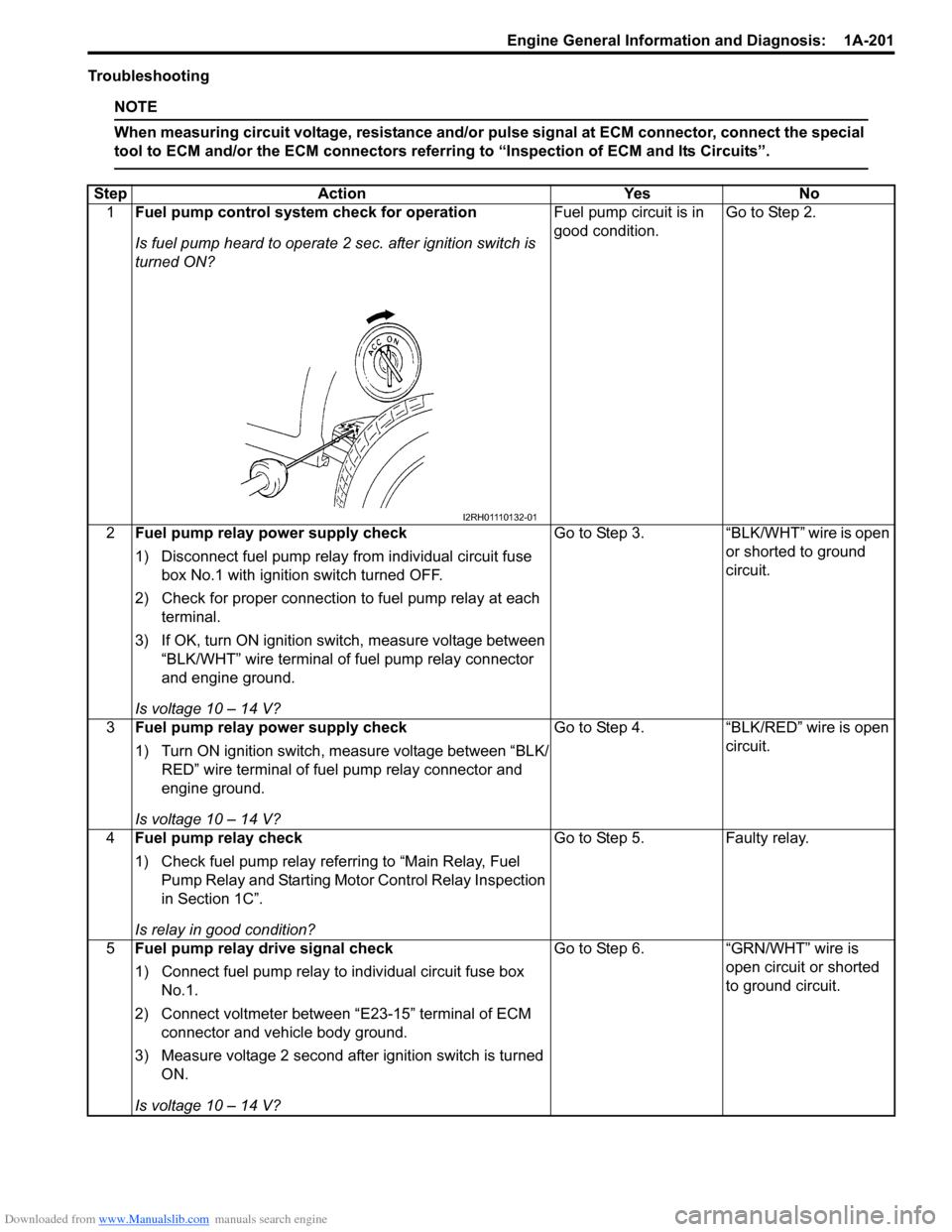
1 Fuel pump control system check for operation
Is fuel pump heard to operate 2 sec. after ignition switch is
turned ON? Fuel pump circuit is in
good condition.
Go to Step 2.
2 Fuel pump relay po wer supply check
1) Disconnect fuel pump relay from individual circuit fuse box No.1 with ignition switch turned OFF.
2) Check for proper connection to fuel pump relay at each terminal.
3) If OK, turn ON ignition switch, measure voltage between “BLK/WHT” wire terminal of fuel pump relay connector
and engine ground.
Is voltage 10 – 14 V? Go to Step 3.
“BLK/WHT” wire is open
or shorted to ground
circuit.
3 Fuel pump relay po wer supply check
1) Turn ON ignition switch, measure voltage between “BLK/ RED” wire terminal of fuel pump relay connector and
engine ground.
Is voltage 10 – 14 V? Go to Step 4.
“BLK/RED” wire is open
circuit.
4 Fuel pump relay check
1) Check fuel pump relay referring to “Main Relay, Fuel
Pump Relay and Starting Moto r Control Relay Inspection
in Section 1C”.
Is relay in good condition? Go to Step 5.
Faulty relay.
5 Fuel pump relay drive signal check
1) Connect fuel pump relay to individual circuit fuse box
No.1.
2) Connect voltmeter between “E23-15” terminal of ECM connector and vehicle body ground.
3) Measure voltage 2 second after ignition switch is turned ON.
Is voltage 10 – 14 V? Go to Step 6.
“GRN/WHT” wire is
open circuit or shorted
to ground circuit.
I2RH01110132-01
Page 254 of 1496
Downloaded from www.Manualslib.com manuals search engine 1A-204 Engine General Information and Diagnosis:
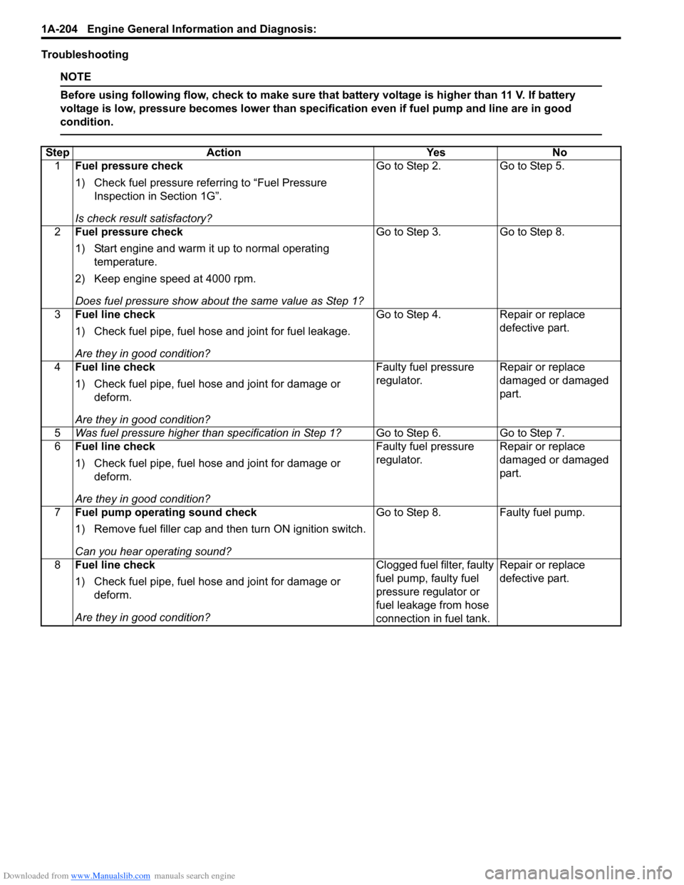
Troubleshooting
NOTE
Before using following flow, check to make sure that battery voltage is higher than 11 V. If battery
voltage is low, pressure becomes lower than specification even if fuel pump and line are in good
condition.
StepAction YesNo
1 Fuel pressure check
1) Check fuel pressure referring to “Fuel Pressure
Inspection in Section 1G”.
Is check result satisfactory? Go to Step 2.
Go to Step 5.
2 Fuel pressure check
1) Start engine and warm it up to normal operating
temperature.
2) Keep engine speed at 4000 rpm.
Does fuel pressure show about the same value as Step 1? Go to Step 3.
Go to Step 8.
3 Fuel line check
1) Check fuel pipe, fuel hose and joint for fuel leakage.
Are they in good condition? Go to Step 4.
Repair or replace
defective part.
4 Fuel line check
1) Check fuel pipe, fuel hose and joint for damage or
deform.
Are they in good condition? Faulty fuel pressure
regulator.
Repair or replace
damaged or damaged
part.
5 Was fuel pressure higher than specification in Step 1? Go to Step 6.Go to Step 7.
6 Fuel line check
1) Check fuel pipe, fuel hose and joint for damage or
deform.
Are they in good condition? Faulty fuel pressure
regulator.
Repair or replace
damaged or damaged
part.
7 Fuel pump operating sound check
1) Remove fuel filler cap and th en turn ON ignition switch.
Can you hear operating sound? Go to Step 8.
Faulty fuel pump.
8 Fuel line check
1) Check fuel pipe, fuel hose and joint for damage or
deform.
Are they in good condition? Clogged fuel filter, faulty
fuel pump, faulty fuel
pressure regulator or
fuel leakage from hose
connection in fuel tank.Repair or replace
defective part.
Page 257 of 1496
Downloaded from www.Manualslib.com manuals search engine Engine General Information and Diagnosis: 1A-207
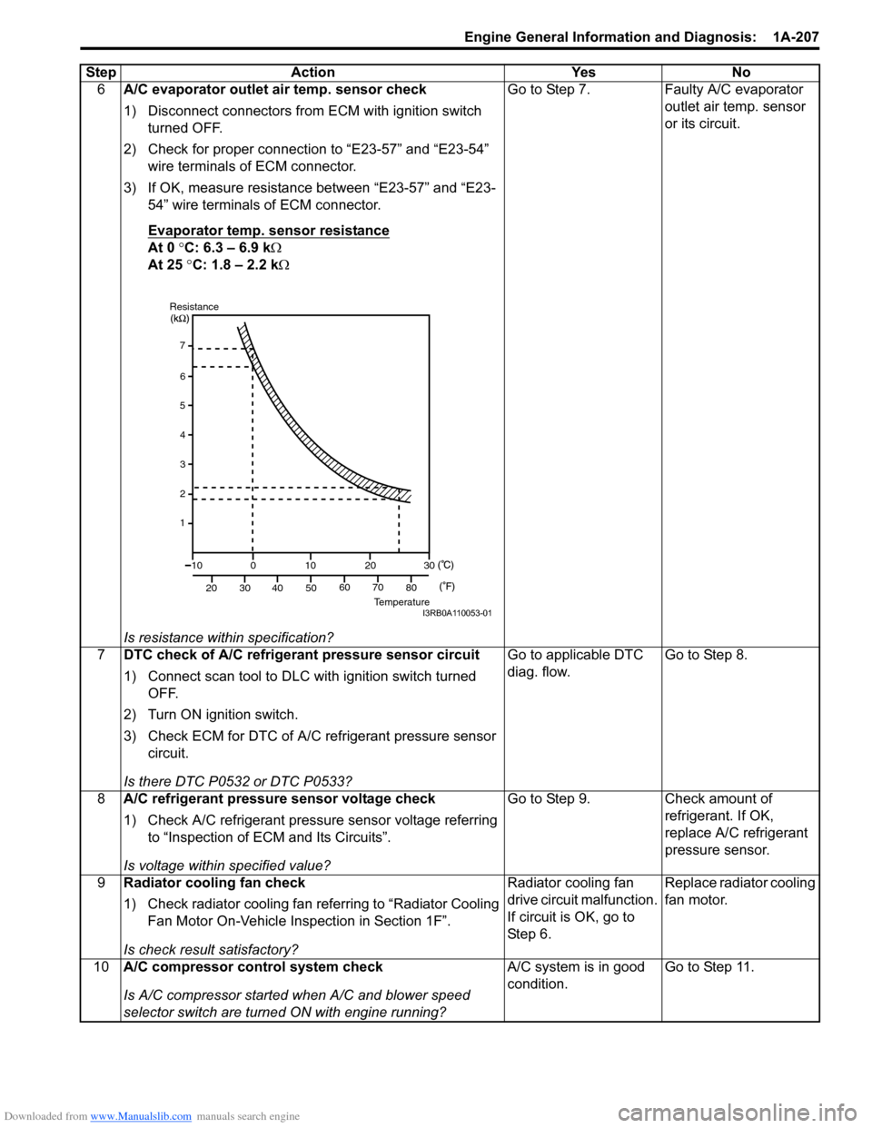
6A/C evaporator outlet air temp. sensor check
1) Disconnect connectors from ECM with ignition switch
turned OFF.
2) Check for proper connection to “E23-57” and “E23-54” wire terminals of ECM connector.
3) If OK, measure resistance between “E23-57” and “E23- 54” wire terminals of ECM connector.
Evaporator temp. sensor resistance
At 0 °C: 6.3 – 6.9 k Ω
At 25 °C: 1.8 – 2.2 k Ω
Is resistance within specification? Go to Step 7. Faulty A/C evaporator
outlet air temp. sensor
or its circuit.
7 DTC check of A/C refrigerant pressure sensor circuit
1) Connect scan tool to DLC with ignition switch turned
OFF.
2) Turn ON ignition switch.
3) Check ECM for DTC of A/C refrigerant pressure sensor circuit.
Is there DTC P0532 or DTC P0533? Go to applicable DTC
diag. flow.
Go to Step 8.
8 A/C refrigerant pressure sensor voltage check
1) Check A/C refrigerant pressure sensor voltage referring
to “Inspection of ECM and Its Circuits”.
Is voltage within specified value? Go to Step 9. Check amount of
refrigerant. If OK,
replace A/C refrigerant
pressure sensor.
9 Radiator cooling fan check
1) Check radiator cooling fan referring to “Radiator Cooling
Fan Motor On-Vehicle Inspection in Section 1F”.
Is check result satisfactory? Radiator cooling fan
drive circuit malfunction.
If circuit is OK, go to
St ep 6 .
Replace radiator cooling
fan motor.
10 A/C compressor control system check
Is A/C compressor started when A/C and blower speed
selector switch are turned ON with engine running? A/C system is in good
condition.
Go to Step 11.
Step Action Yes No
7
6
5
4
3
2
1
10
20 30
40 50
0
10
2030
60 70 80
ResistanceTemperatureI3RB0A110053-01
Page 269 of 1496
Downloaded from www.Manualslib.com manuals search engine Aux. Emission Control Devices: 1B-2
EVAP Canister Purge Valve and Its Circuit
Inspection
S7RS0B1206002
WARNING!
Do not apply vacuum by mouth; otherwise
harmful fuel vapor can be breathed in.
CAUTION!
Do not apply vacuum more than –86 kPa (–
12.47 psi); otherwise EVAP canister purge
valve could be damaged.
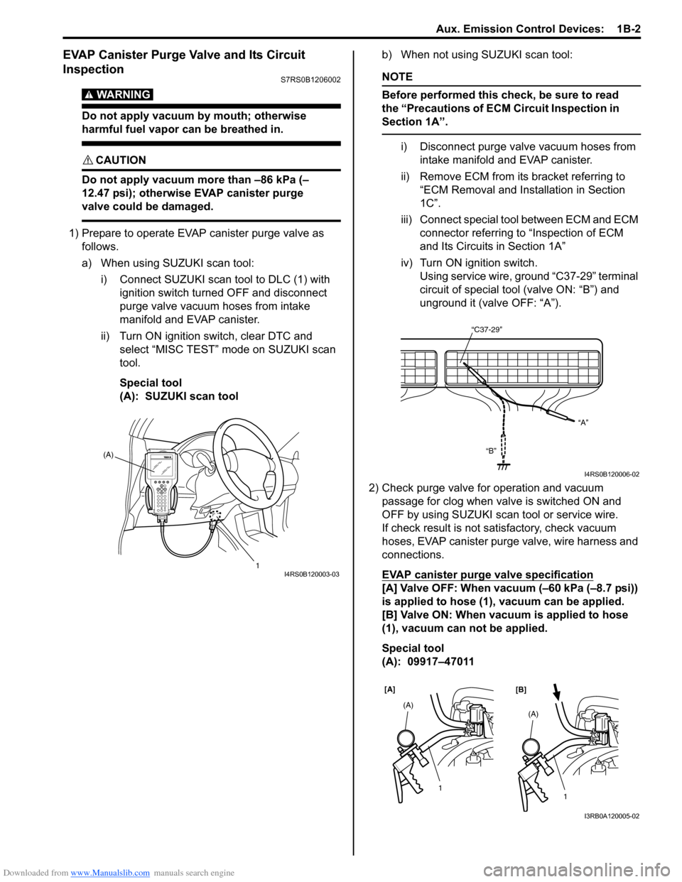
1) Prepare to operate EVAP canister purge valve as follows.
a) When using SUZUKI scan tool:
i) Connect SUZUKI scan tool to DLC (1) with ignition switch turned OFF and disconnect
purge valve vacuum hoses from intake
manifold and EVAP canister.
ii) Turn ON ignition switch, clear DTC and select “MISC TEST” mode on SUZUKI scan
tool.
Special tool
(A): SUZUKI scan tool b) When not using SUZUKI scan tool:
NOTE
Before performed this check, be sure to read
the “Precautions of ECM Circuit Inspection in
Section 1A”.
i) Disconnect purge valve vacuum hoses from
intake manifold and EVAP canister.
ii) Remove ECM from it s bracket referring to
“ECM Removal and Inst allation in Section
1C”.
iii) Connect special tool between ECM and ECM connector referring to “Inspection of ECM
and Its Circuits in Section 1A”
iv) Turn ON ignition switch. Using service wire, ground “C37-29” terminal
circuit of special tool (valve ON: “B”) and
unground it (valve OFF: “A”).
2) Check purge valve for operation and vacuum passage for clog when valve is switched ON and
OFF by using SUZUKI scan tool or service wire.
If check result is not satisfactory, check vacuum
hoses, EVAP canister purge valve, wire harness and
connections.
EVAP canister purge valve specification
[A] Valve OFF: When vacuum (–60 kPa (–8.7 psi))
is applied to hose (1), vacuum can be applied.
[B] Valve ON: When vacuum is applied to hose
(1), vacuum can not be applied.
Special tool
(A): 09917–47011
(A)
1
I4RS0B120003-03
“C37-29”“A”
“B”
I4RS0B120006-02
[A] [B]
1
(A)1
(A)
I3RB0A120005-02