replace engine mount SUZUKI SWIFT 2008 2.G Service Owners Manual
[x] Cancel search | Manufacturer: SUZUKI, Model Year: 2008, Model line: SWIFT, Model: SUZUKI SWIFT 2008 2.GPages: 1496, PDF Size: 34.44 MB
Page 1287 of 1496
Downloaded from www.Manualslib.com manuals search engine Lighting Systems: 9B-5
Interior Light Symptom DiagnosisS7RS0B9204008
NOTE
• Use of SUZUKI scan tool makes it easy to check whether a faulty condition is on the input side or
output side of BCM. For checking procedure, re fer to “Diagnosis Using Output Test Function of
SUZUKI Scan Tool” under “Scan Tool Data in Section 10B”.
• Check each part in the order from the top of the following list.
Repair Instructions
Headlight Housing Removal and InstallationS7RS0B9206001
Removal 1) Disconnect negative (–) cable at battery.
2) Remove front bumper. Refer to “Front Bumper and Rear Bumper Componen ts in Section 9K”.
3) Remove headlight mounting bolts.
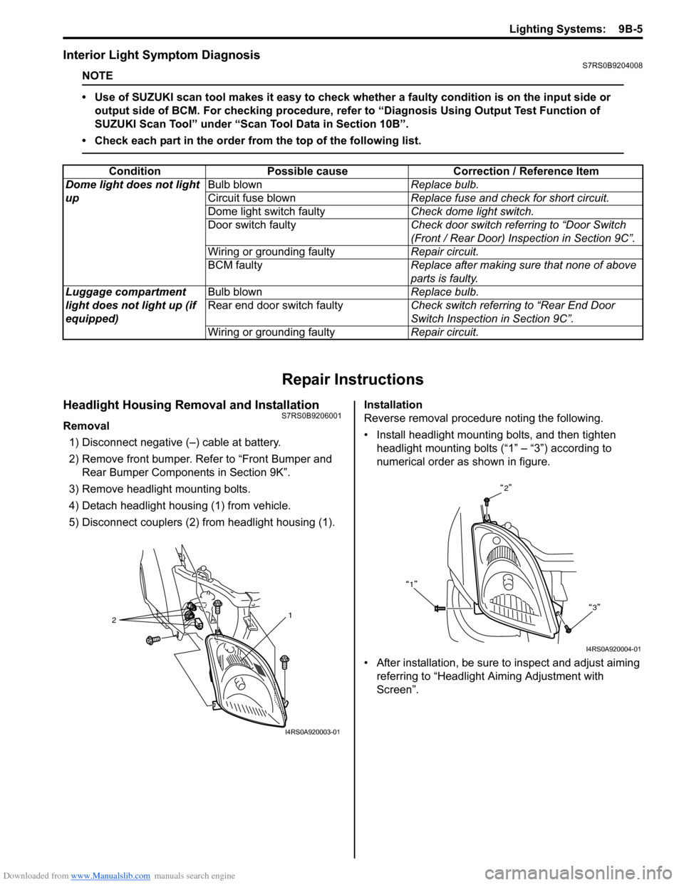
4) Detach headlight housing (1) from vehicle.
5) Disconnect couplers (2) from headlight housing (1). Installation
Reverse removal procedure noting the following.
• Install headlight mounting bolts, and then tighten
headlight mounting bolts (“1” – “3”) according to
numerical order as shown in figure.
• After installation, be sure to inspect and adjust aiming referring to “Headlight Aiming Adjustment with
Screen”.
Condition Possible cause Correction / Reference Item
Dome light does not light
up Bulb blown
Replace bulb.
Circuit fuse blown Replace fuse and check for short circuit.
Dome light switch faulty Check dome light switch.
Door switch faulty Check door switch referring to “Door Switch
(Front / Rear Door) Inspection in Section 9C”.
Wiring or grounding faulty Repair circuit.
BCM faulty Replace after making sure that none of above
parts is faulty.
Luggage compartment
light does not light up (if
equipped) Bulb blown
Replace bulb.
Rear end door switch faulty Check switch referring to “Rear End Door
Switch Inspection in Section 9C”.
Wiring or grounding faulty Repair circuit.
2 1
I4RS0A920003-01
2
1 3
I4RS0A920004-01
Page 1302 of 1496
Downloaded from www.Manualslib.com manuals search engine 9C-7 Instrumentation / Driver Info. / Horn:
Engine Coolant Temperature (ECT) Meter Symptom DiagnosisS7RS0B9304003
Fuel Meter Symptom DiagnosisS7RS0B9304004
Low Fuel Warning Light Symptom DiagnosisS7RS0B9304005
NOTE
Confirm that fuel meter is in good condition before referring to the following possible causes.
• When fuel level sensor circuit is open or short, fuel meter indicates empty even if fuel tank does not empty.
• The low fuel warning light comes ON when fu el level is lower than specification below.
Low fuel warning light operation:
ConditionPossible cause Correction / Reference Item
Engine coolant
temperature (ECT) meter
shows no operation or
incorrect operation Circuit fuse blown
Replace fuse and check for short circuit.
ECT sensor faulty Check ECT sensor referring to “ECT Sensor
Inspection in Section 1C”.
Wiring and/or grounding faulty Repair as necessary.
Combination meter faulty Replace combination meter.
ECM faulty Replace after making sure that none of above
parts is faulty.
ConditionPossible cause Correction / Reference Item
Fuel meter shows no
operation or incorrect
operation Circuit fuse blown
Replace fuse and check for short circuit.
Fuel level sensor faulty Check fuel level sensor referring to “Fuel Level
Sensor Inspection”.
Wiring and/or grounding faulty Repair as necessary.
Combination meter faulty Replace combination meter.
Low fuel warning light operation: Fuel amount: Resistance of fuel level sensor:
ON Approx. 6.5 liter Approx. 251 Ω
Condition Possible cause Correction / Reference Item
Low fuel warning light
does not come ON when
fuel level is lower than
specification Circuit fuse blown
Replace fuse and check for short circuit.
Fuel level sensor faulty Check fuel level sensor referring to “Fuel Level
Sensor Inspection”.
Wiring and/or grounding faulty Repair as necessary.
Combination meter faulty Replace combination meter.
Low fuel warning light
comes ON steady Low fuel
Refill fuel.
Fuel level sensor faulty Check fuel level sensor referring to “Fuel Level
Sensor Inspection”.
Wiring and/or grounding faulty Repair as necessary.
Combination meter faulty Replace combination meter.
Page 1315 of 1496
Downloaded from www.Manualslib.com manuals search engine Instrumentation / Driver Info. / Horn: 9C-20
Rear Speaker Removal and InstallationS7RS0B9306019
Removal
1) Remove rear door trim referring to Step 1) to 3) of “Rear Door Glass Removal and Installation in
Section 9E”.
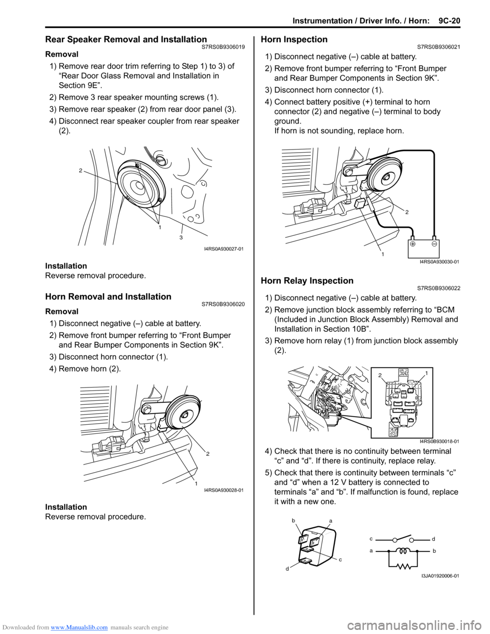
2) Remove 3 rear speaker mounting screws (1).
3) Remove rear speaker (2) from rear door panel (3).
4) Disconnect rear speaker coupler from rear speaker (2).
Installation
Reverse removal procedure.
Horn Removal and InstallationS7RS0B9306020
Removal 1) Disconnect negative (–) cable at battery.
2) Remove front bumper referring to “Front Bumper and Rear Bumper Components in Section 9K”.
3) Disconnect horn connector (1).
4) Remove horn (2).
Installation
Reverse removal procedure.
Horn InspectionS7RS0B9306021
1) Disconnect negative (–) cable at battery.
2) Remove front bumper referring to “Front Bumper and Rear Bumper Components in Section 9K”.
3) Disconnect horn connector (1).
4) Connect battery positive (+) terminal to horn
connector (2) and negative (–) terminal to body
ground.
If horn is not sounding, replace horn.
Horn Relay InspectionS7RS0B9306022
1) Disconnect negative (–) cable at battery.
2) Remove junction block assembly referring to “BCM (Included in Junction Bl ock Assembly) Removal and
Installation in Section 10B”.
3) Remove horn relay (1) from junction block assembly (2).
4) Check that there is no continuity between terminal “c” and “d”. If there is continuity, replace relay.
5) Check that there is continuity between terminals “c” and “d” when a 12 V battery is connected to
terminals “a” and “b”. If malfunction is found, replace
it with a new one.
1
2
3
I4RS0A930027-01
12I4RS0A930028-01
1 2I4RS0A930030-01
1
2
I4RS0B930018-01
ba
c
d c
a
d
bI3JA01920006-01
Page 1317 of 1496
Downloaded from www.Manualslib.com manuals search engine Instrumentation / Driver Info. / Horn: 9C-22
Remote Audio Control Switch Inspection (If
Equipped)
S7RS0B9306024
1) Remove driver air bag (inflator) module referring to
“Driver Air Bag (Inflator) Module Removal and
Installation in Section 8B”.
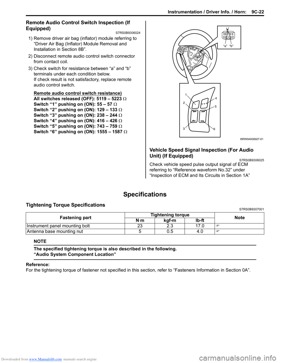
2) Disconnect remote audio control switch connector
from contact coil.
3) Check switch for resistance between “a” and “b” terminals under each condition below.
If check result is not satisfactory, replace remote
audio control switch.
Remote audio control switch resistance)
All switches released (OFF): 5119 – 5223 Ω
Switch “1” pushing on (ON): 55 – 57 Ω
Switch “2” pushing on (ON): 129 – 133 Ω
Switch “3” pushing on (ON): 238 – 244 Ω
Switch “4” pushing on (ON): 416 – 426 Ω
Switch “5” pushing on (ON): 743 – 759 Ω
Switch “6” pushing on (ON): 1555 – 1587 Ω
Vehicle Speed Signal Inspection (For Audio
Unit) (If Equipped)
S7RS0B9306025
Check vehicle speed pulse output signal of ECM
referring to “Reference waveform No.32” under
“Inspection of ECM and Its Circuits in Section 1A”
Specifications
Tightening Torque SpecificationsS7RS0B9307001
NOTE
The specified tightening torque is also described in the following.
“Audio System Component Location”
Reference:
For the tightening torque of fastener not specified in this section, refer to “Fasteners Information in Section 0A”.
“b”“a”
1
2
3 4
5
6
I5RW0A930027-01
Fastening part Tightening torque
Note
N ⋅mkgf-mlb-ft
Instrument panel mounting bolt 23 2.3 17.0 �)
Antenna base mounting nut 5 0.5 4.0 �)
Page 1327 of 1496
Downloaded from www.Manualslib.com manuals search engine Wipers / Washers: 9D-10
Rear Wiper Relay Removal and InstallationS7RS0B9406012
Removal1) Disconnect negative (–) cable at battery.
2) Remove junction block assembly referring to “BCM (Included in Junction Block Assembly) Removal and
Installation in Section 10B”.
3) Remove rear wiper relay.
Installation
Reverse removal procedure for installation.
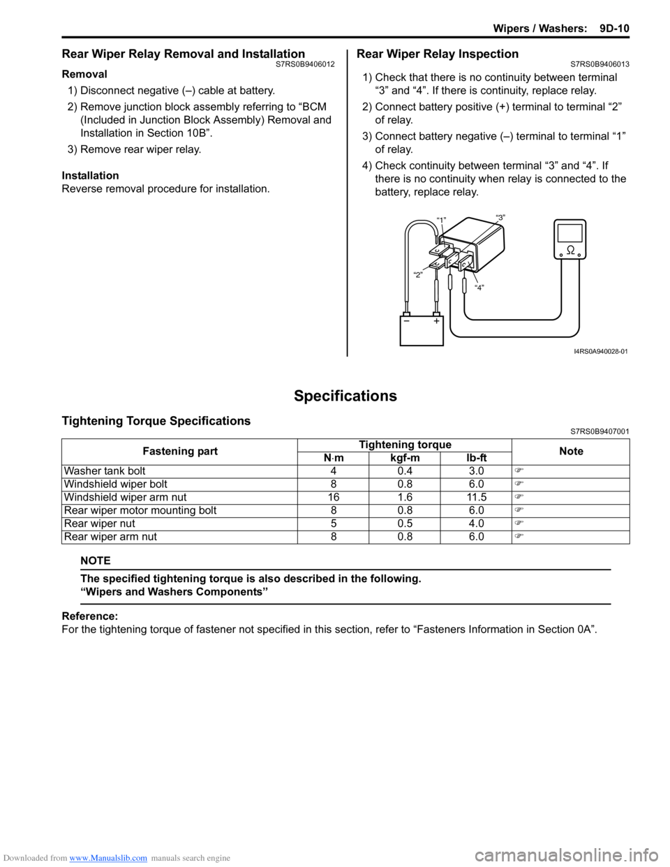
Rear Wiper Relay InspectionS7RS0B9406013
1) Check that there is no continuity between terminal “3” and “4”. If there is continuity, replace relay.
2) Connect battery positive (+ ) terminal to terminal “2”
of relay.
3) Connect battery negative (–) terminal to terminal “1” of relay.
4) Check continuity between terminal “3” and “4”. If
there is no continuity when relay is connected to the
battery, replace relay.
Specifications
Tightening Torque SpecificationsS7RS0B9407001
NOTE
The specified tightening torque is also described in the following.
“Wipers and Washers Components”
Reference:
For the tightening torque of fastener not specified in this section, refer to “Fasteners Information in Section 0A”.
“4”
“2” “1”
“3”
I4RS0A940028-01
Fastening part Tightening torque
Note
N ⋅mkgf-mlb-ft
Washer tank bolt 4 0.4 3.0 �)
Windshield wiper bolt 8 0.8 6.0 �)
Windshield wiper arm nut 16 1.6 11.5 �)
Rear wiper motor mounting bolt 8 0.8 6.0 �)
Rear wiper nut 5 0.5 4.0 �)
Rear wiper arm nut 8 0.8 6.0 �)
Page 1336 of 1496
Downloaded from www.Manualslib.com manuals search engine 9E-9 Glass / Windows / Mirrors:
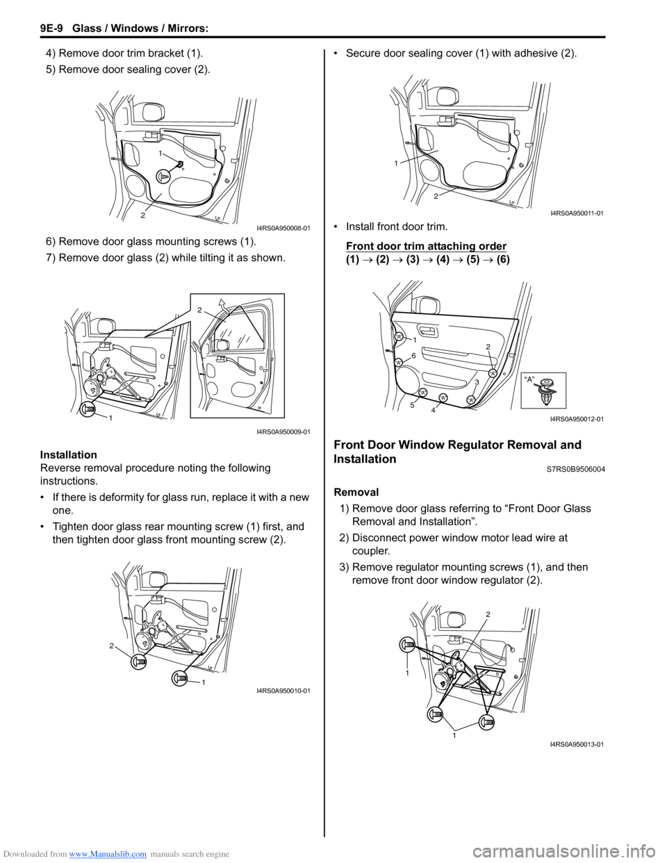
4) Remove door trim bracket (1).
5) Remove door sealing cover (2).
6) Remove door glass mounting screws (1).
7) Remove door glass (2) while tilting it as shown.
Installation
Reverse removal procedure noting the following
instructions.
• If there is deformity for glass run, replace it with a new one.
• Tighten door glass rear mounting screw (1) first, and then tighten door glass front mounting screw (2). • Secure door sealing cover (1) with adhesive (2).
• Install front door trim.
Front door trim attaching order
(1) → (2) → (3) → (4) → (5) → (6)
Front Door Window Regulator Removal and
Installation
S7RS0B9506004
Removal
1) Remove door glass referring to “Front Door Glass Removal and Installation”.
2) Disconnect power window motor lead wire at coupler.
3) Remove regulator mounting screws (1), and then remove front door window regulator (2).
1
2
I4RS0A950008-01
2
1
I4RS0A950009-01
1
2
I4RS0A950010-01
2
1
I4RS0A950011-01
“A”“A”
“A”
“A”
“A”“A”“A”
1 2
3
4
5 6
I4RS0A950012-01
1
1
2
I4RS0A950013-01
Page 1338 of 1496
Downloaded from www.Manualslib.com manuals search engine 9E-11 Glass / Windows / Mirrors:
Rear Door Glass Removal and InstallationS7RS0B9506007
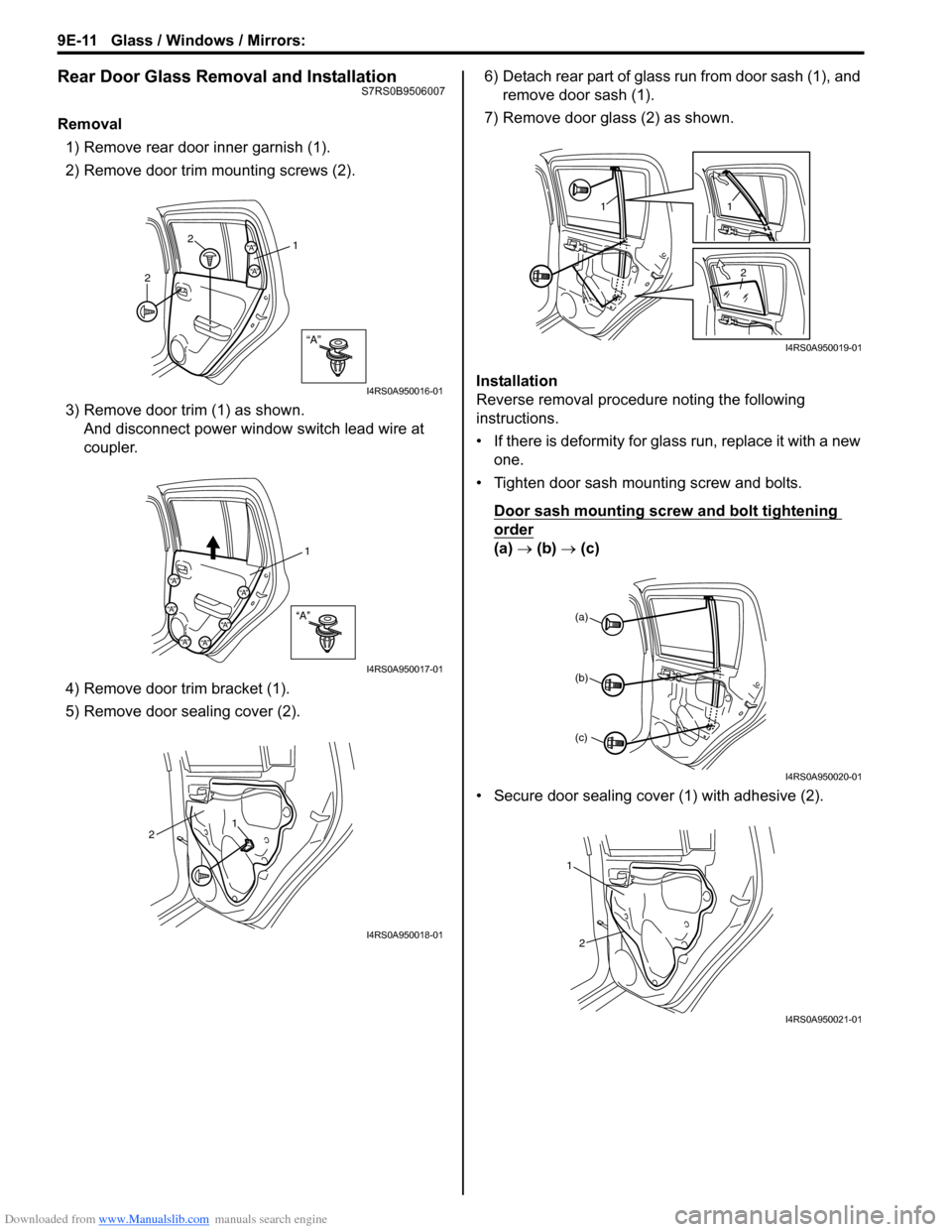
Removal1) Remove rear door inner garnish (1).
2) Remove door trim mounting screws (2).
3) Remove door trim (1) as shown. And disconnect power wi ndow switch lead wire at
coupler.
4) Remove door trim bracket (1).
5) Remove door sealing cover (2). 6) Detach rear part of glass run from door sash (1), and
remove door sash (1).
7) Remove door glass (2) as shown.
Installation
Reverse removal procedure noting the following
instructions.
• If there is deformity for glass run, replace it with a new one.
• Tighten door sash mounting screw and bolts.
Door sash mounting screw and bolt tightening
order
(a) → (b) → (c)
• Secure door sealing cover (1) with adhesive (2).
“A”
“A”
“A”
2
2 1
I4RS0A950016-01
“A”
“A”
“A”
“A”“A”
“A”
“A”
1
I4RS0A950017-01
1
2
I4RS0A950018-01
1
1
2
I4RS0A950019-01
(a)
(b)
(c)
I4RS0A950020-01
1
2
I4RS0A950021-01
Page 1345 of 1496
Downloaded from www.Manualslib.com manuals search engine Glass / Windows / Mirrors: 9E-18
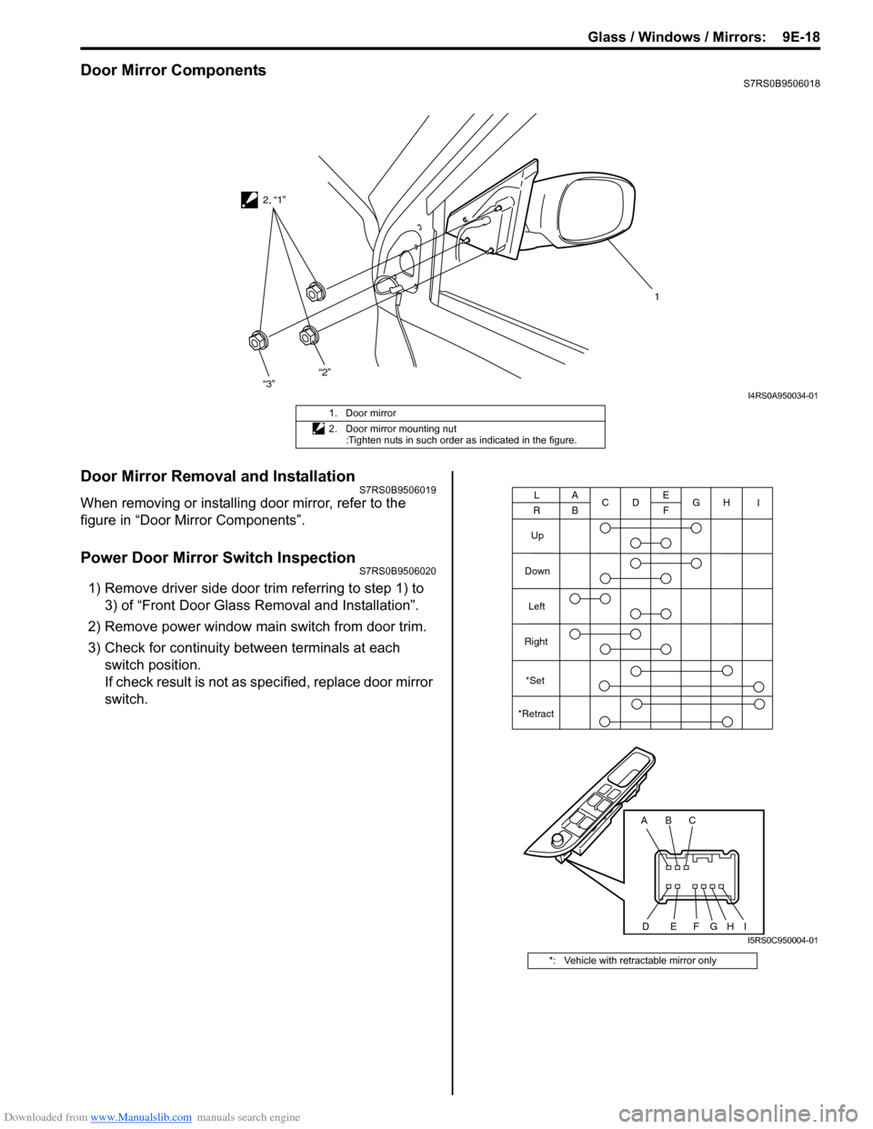
Door Mirror ComponentsS7RS0B9506018
Door Mirror Removal and InstallationS7RS0B9506019
When removing or installing door mirror, refer to the
figure in “Door Mirror Components”.
Power Door Mirror Switch InspectionS7RS0B9506020
1) Remove driver side door trim referring to step 1) to 3) of “Front Door Glass Removal and Installation”.
2) Remove power window main switch from door trim.
3) Check for continuity between terminals at each switch position.
If check result is not as specified, replace door mirror
switch.
1
2, “1”
“3”
“2”
I4RS0A950034-01
1. Door mirror
2. Door mirror mounting nut
:Tighten nuts in such order as indicated in the figure.
*: Vehicle with retractable mirror only
ABC
DEFG
A
B C
D E
F G
Up
Down Left
Right
L
RH I
*Set
*Retract
HII5RS0C950004-01
Page 1373 of 1496
Downloaded from www.Manualslib.com manuals search engine Hood / Fenders / Doors: 9J-4
Installation
Reverse removal procedure to install door assembly
noting the following instructions.
• When replacing door, coat replacement door inside with wax for proper anti-cor rosion treatment. Refer to
“Sealant Application Areas in Section 9L”.
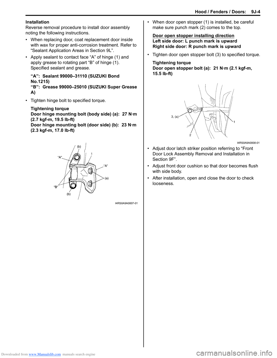
• Apply sealant to contact face “A” of hinge (1) and apply grease to rotating part “B” of hinge (1).
Specified sealant and grease.
“A”: Sealant 99000–31110 (SUZUKI Bond
No.1215)
“B”: Grease 99000–25010 (SUZUKI Super Grease
A)
• Tighten hinge bolt to specified torque. Tightening torque
Door hinge mounting bolt (body side) (a): 27 N·m
(2.7 kgf-m, 19.5 lb-ft)
Door hinge mounting bolt (door side) (b): 23 N·m
(2.3 kgf-m, 17.0 lb-ft) • When door open stopper (1) is installed, be careful
make sure punch mark (2) comes to the top.
Door open stopper installing direction
Left side door: L punch mark is upward
Right side door: R punch mark is upward
• Tighten door open stopper bolt (3) to specified torque. Tightening torque
Door open stopper bolt (a): 21 N·m (2.1 kgf-m,
15.5 lb-ft)
• Adjust door latch striker position referring to “Front Door Lock Assembly Removal and Installation in
Section 9F”.
• Adjust front door cushion so that door becomes flush with side body.
• After installation, open and close the door to check looseness.
I4RS0A9A0007-01
I4RS0A9A0008-01
Page 1388 of 1496
Downloaded from www.Manualslib.com manuals search engine 9L-1 Paint / Coatings:
Body, Cab and Accessories
Paint / Coatings
General Description
Anti-Corrosion Treatment ConstructionS7RS0B9C01001
WARNING!
Standard shop practices, particularly eye protection, should be followed during the performance of the
following operations to avoid personal injury.
As rust proof treatment, steel sheets are given corrosion resistance on the interior and/or exterior.
These corrosion resistance steel sheet materials ar e called one of two-side galvanized steel sheets.
It is for the sake of rust protection that these materials are selected and given a variety of treatments as described
blow.
• Steel sheets are treated with cathodic electro primer which is excellent in corrosion resistance.
• Rust proof wax coatings are applied to door and side sill insides where mois ture is liable to stay.
• Vinyl coating is applied to body underside and wheel housing inside.
• Sealer is applied to door hem, engine compartment steel sheet-to-steel sheet joint, and the like portions to prevent water penetration and resulting in rust occurrence.
In panel replacement or collision damage repair, leaving the relevant area untreated as it is in any operation which
does disturb the rust proof treatment will cause corrosion to th at area. Therefore, it is the essential function of any
repair operation to correctly recoat t he related surfaces of the relevant area.
All the metal panels are coated with metal conditioners an d primer coating during vehicle production. Following the
repair and/or replacement parts installation, every access ible bare metal surface should be cleaned and coated with
rust proof primer. Perform this operation prior to the application of sealer and rust proof wax coating.
Sealer is applied to the spec ific joints of a vehicle during production. The sealer is intended to prevent dust from
entering the vehicle and serves also as an anti corrosion barrier. The sealer is applied to the door and hood hem areas
and between panels. Correct and reseal the originally sealed joints if damaged. Reseal the attaching joints of a new
replacement panel and reseal the hem area of a replacement door or hood.
Use a quality sealer to seal the flanged joints, overlap joints and seams. The sealer must have flexible characteristics
and paint ability after it’s applied to repair areas.
For the sealer to fill open joints, use caulking material. Select a sealer in conf ormance with the place and purpose of a
specific use. Observe the ma nufacturer’s label-stand instructions when using the sealer.
In many cases, repaired places require color painting. When this is required, follow the ordinary techniques specified
for the finish preparation, color painting and undercoating build-up.
Rust proof wax, a penetrative compound, is applied to the metal-to-metal surfaces (door and side sill insides) where it
is difficult to use ordinary undercoating material for coating. Therefore, when selecting the rust proof wax, it may be the
penetrative type.
During the undercoating (vinyl coating) application, care should be taken that sealer is not applied to the engine-
related parts and shock absorber mounting or rotating parts. Following the under coating, make sure that body drain
holes are kept open.
The sequence of the application steps of the anti-corrosion materials are as follows:
1) Clean and prepare the metal surface.
2) Apply primer.
3) Apply sealer (all joints sealed originally).
4) Apply color in areas where color is required such as hem flanges, exposed joints and under body components.
5) Apply anti corrosion compound (penetrative wax).
6) Apply undercoating (rust proof material).