Hydraulic SUZUKI SWIFT 2008 2.G Service Workshop Manual
[x] Cancel search | Manufacturer: SUZUKI, Model Year: 2008, Model line: SWIFT, Model: SUZUKI SWIFT 2008 2.GPages: 1496, PDF Size: 34.44 MB
Page 840 of 1496
Downloaded from www.Manualslib.com manuals search engine 5B-26 Manual Transmission/Transaxle:
Input Shaft Assembly Disassembly and
Reassembly
S7RS0B5206019
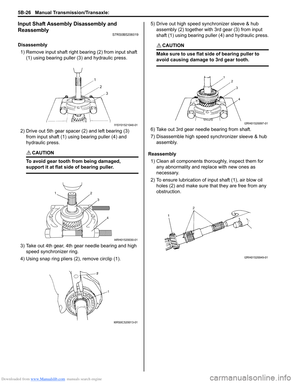
Disassembly1) Remove input shaft right bearing (2) from input shaft (1) using bearing puller (3) and hydraulic press.
2) Drive out 5th gear spacer (2) and left bearing (3) from input shaft (1) using bearing puller (4) and
hydraulic press.
CAUTION!
To avoid gear tooth from being damaged,
support it at flat side of bearing puller.
3) Take out 4th gear, 4th gear needle bearing and high speed synchronizer ring.
4) Using snap ring pliers (2), remove circlip (1). 5) Drive out high speed synchronizer sleeve & hub
assembly (2) together with 3rd gear (3) from input
shaft (1) using bearing puller (4) and hydraulic press.
CAUTION!
Make sure to use flat side of bearing puller to
avoid causing damage to 3rd gear tooth.
6) Take out 3rd gear needle bearing from shaft.
7) Disassemble high speed synchronizer sleeve & hub assembly.
Reassembly 1) Clean all components thoroughly, inspect them for any abnormality and replace with new ones as
necessary.
2) To ensure lubrication of input shaft (1), air blow oil holes (2) and make sure that they are free from any
obstruction.
IYSY01521048-01
1 2
3
4
I4RH01520030-01
I6RS0C520013-01
I2RH01520097-01
I2RH01520049-01
Page 842 of 1496
Downloaded from www.Manualslib.com manuals search engine 5B-28 Manual Transmission/Transaxle:
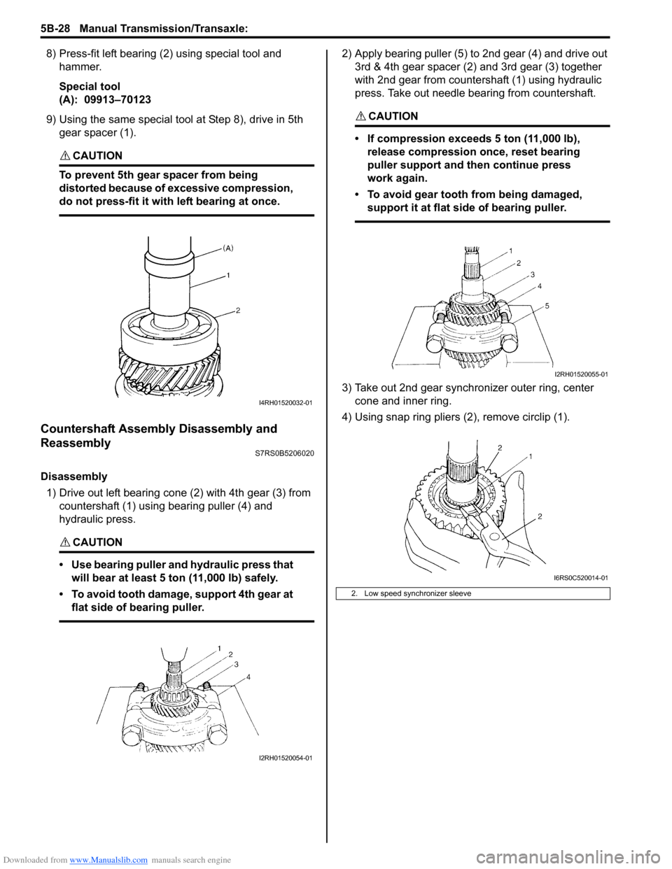
8) Press-fit left bearing (2) using special tool and hammer.
Special tool
(A): 09913–70123
9) Using the same special tool at Step 8), drive in 5th
gear spacer (1).
CAUTION!
To prevent 5th gear spacer from being
distorted because of excessive compression,
do not press-fit it with left bearing at once.
Countershaft Assembly Disassembly and
Reassembly
S7RS0B5206020
Disassembly
1) Drive out left bearing cone (2) with 4th gear (3) from countershaft (1) using bearing puller (4) and
hydraulic press.
CAUTION!
• Use bearing puller and hydraulic press that will bear at least 5 ton (11,000 lb) safely.
• To avoid tooth damage, support 4th gear at flat side of bearing puller.
2) Apply bearing puller (5) to 2nd gear (4) and drive out 3rd & 4th gear spacer (2) and 3rd gear (3) together
with 2nd gear from countershaft (1) using hydraulic
press. Take out needle bearing from countershaft.
CAUTION!
• If compression exceeds 5 ton (11,000 lb), release compression once, reset bearing
puller support and then continue press
work again.
• To avoid gear tooth from being damaged, support it at flat side of bearing puller.
3) Take out 2nd gear synchronizer outer ring, center cone and inner ring.
4) Using snap ring pliers (2), remove circlip (1).
I4RH01520032-01
I2RH01520054-01
2. Low speed synchronizer sleeve
I2RH01520055-01
I6RS0C520014-01
Page 843 of 1496
Downloaded from www.Manualslib.com manuals search engine Manual Transmission/Transaxle: 5B-29
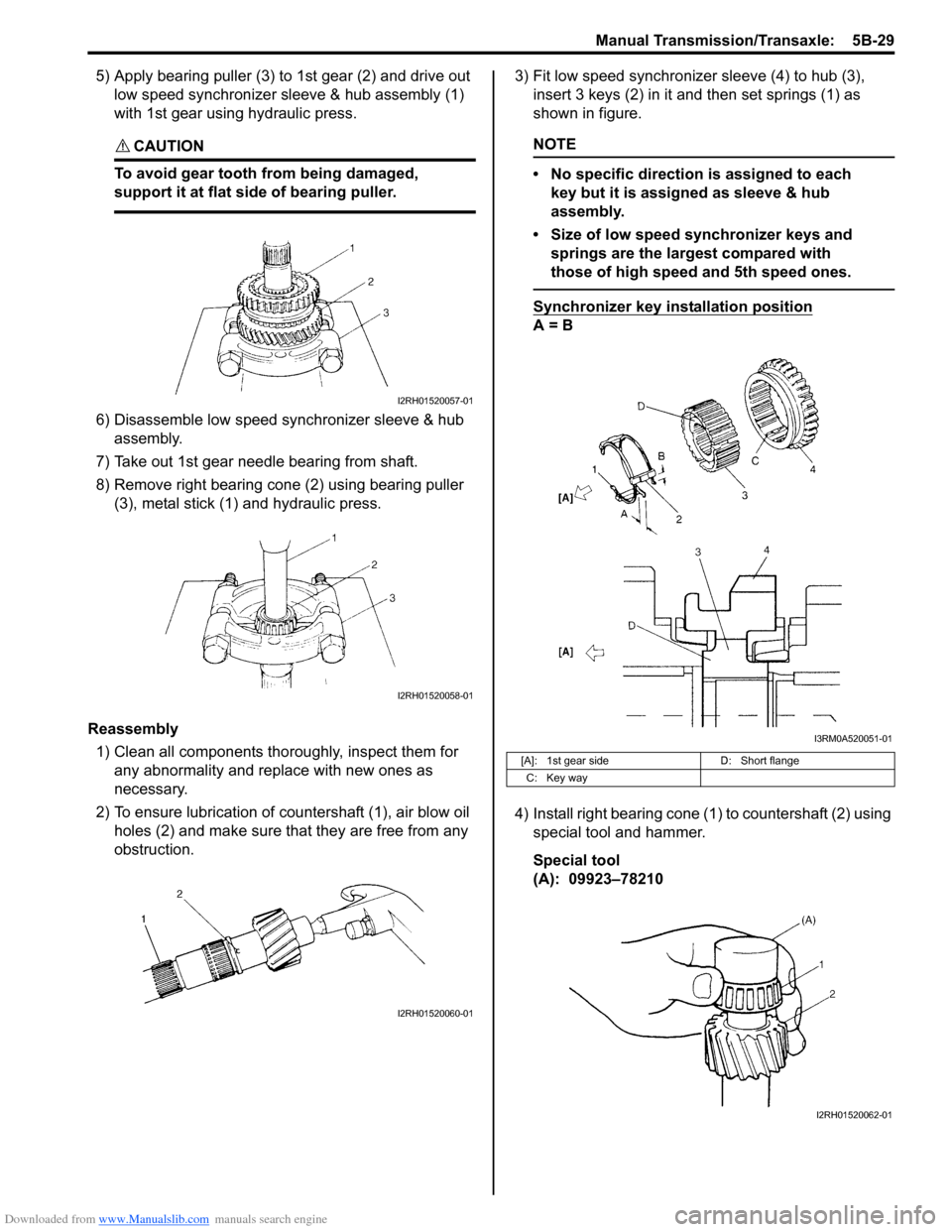
5) Apply bearing puller (3) to 1st gear (2) and drive out low speed synchronizer sleeve & hub assembly (1)
with 1st gear using hydraulic press.
CAUTION!
To avoid gear tooth from being damaged,
support it at flat side of bearing puller.
6) Disassemble low speed synchronizer sleeve & hub assembly.
7) Take out 1st gear needle bearing from shaft.
8) Remove right bearing cone (2) using bearing puller (3), metal stick (1) and hydraulic press.
Reassembly 1) Clean all components thor oughly, inspect them for
any abnormality and replace with new ones as
necessary.
2) To ensure lubrication of countershaft (1), air blow oil holes (2) and make sure that they are free from any
obstruction. 3) Fit low speed synchronizer sleeve (4) to hub (3),
insert 3 keys (2) in it and then set springs (1) as
shown in figure.
NOTE
• No specific direction is assigned to each key but it is assigned as sleeve & hub
assembly.
• Size of low speed synchronizer keys and springs are the largest compared with
those of high speed and 5th speed ones.
Synchronizer key installation position
A = B
4) Install right bearing cone (1) to countershaft (2) using special tool and hammer.
Special tool
(A): 09923–78210
I2RH01520057-01
I2RH01520058-01
I2RH01520060-01
[A]: 1st gear side D: Short flange
C: Key way
I3RM0A520051-01
I2RH01520062-01
Page 844 of 1496
Downloaded from www.Manualslib.com manuals search engine 5B-30 Manual Transmission/Transaxle:
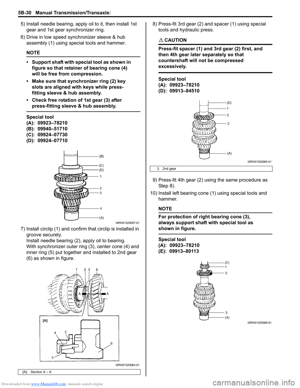
5) Install needle bearing, apply oil to it, then install 1st gear and 1st gear synchronizer ring.
6) Drive in low speed synchronizer sleeve & hub assembly (1) using special tools and hammer.
NOTE
• Support shaft with special tool as shown in figure so that retainer of bearing cone (4)
will be free from compression.
• Make sure that synchronizer ring (2) key slots are aligned with keys while press-
fitting sleeve & hub assembly.
• Check free rotation of 1st gear (3) after press-fitting sleeve & hub assembly.
Special tool
(A): 09923–78210
(B): 09940–51710
(C): 09924–07730
(D): 09924–07710
7) Install circlip (1) and confirm that circlip is installed in groove securely.
Install needle bearing (2), apply oil to bearing.
With synchronizer outer ring (3), center cone (4) and
inner ring (5) put together and installed to 2nd gear
(6) as shown in figure. 8) Press-fit 3rd gear (2) and spacer (1) using special
tools and hydraulic press.
CAUTION!
Press-fit spacer (1) and 3rd gear (2) first, and
then 4th gear later separately so that
countershaft will not be compressed
excessively.
Special tool
(A): 09923–78210
(D): 09913–84510
9) Press-fit 4th gear (2) using the same procedure as Step 8).
10) Install left bearing cone (1) using special tools and hammer.
NOTE
For protection of right bearing cone (3),
always support shaft with special tool as
shown in figure.
Special tool
(A): 09923–78210
(E): 09913–80113
[A]: Section A – A
I4RH01520057-01
I2RH01520064-01
3. 2nd gear
I2RH01520065-01
I2RH01520066-01
Page 855 of 1496
Downloaded from www.Manualslib.com manuals search engine Clutch: 5C-3
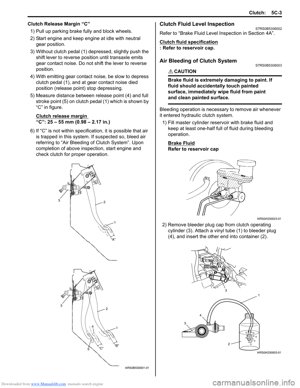
Clutch Release Margin “C”1) Pull up parking brake fully and block wheels.
2) Start engine and keep engine at idle with neutral gear position.
3) Without clutch pedal (1) dep ressed, slightly push the
shift lever to re verse position until transaxle emits
gear contact noise. Do not shift the lever to reverse
position.
4) With emitting gear contact noise, be slow to depress clutch pedal (1), and at gear contact noise died
position (release point) stop depressing.
5) Measure distance between release point (4) and full stroke point (5) on clutch pedal (1) which is shown by
“C” in figure.
Clutch release margin
“C”: 25 – 55 mm (0.98 – 2.17 in.)
6) If “C” is not within specificat ion, it is possible that air
is trapped in this system. If suspected so, bleed air
referring to “Air Bleeding of Clutch System”. Upon
completion of above inspection, start engine and
check clutch for proper operation.
Clutch Fluid Level InspectionS7RS0B5306002
Refer to “Brake Fluid Level Inspection in Section 4A”.
Clutch fluid specification
: Refer to reservoir cap.
Air Bleeding of Clutch SystemS7RS0B5306003
CAUTION!
Brake fluid is extremely damaging to paint. If
fluid should accidentally touch painted
surface, immediately wipe fluid from paint
and clean painted surface.
Bleeding operation is necessary to remove air whenever
it entered hydraulic clutch system.
1) Fill master cylinder reservoir with brake fluid and keep at least one-half full of fluid during bleeding
operation.
Brake Fluid
Refer to reservoir cap
2) Remove bleeder plug cap from clutch operating cylinder (3). Attach a vinyl tube (1) to bleeder plug
(4), and insert the other end into container (2).
2
1
“A”
3
2
1
3
“B”
“C”
4
5
I4RS0B530001-01
I4RS0A530023-01
3 4 1
2
3
I4RS0A530003-01
Page 856 of 1496
Downloaded from www.Manualslib.com manuals search engine 5C-4 Clutch:
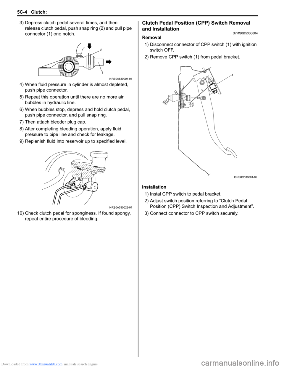
3) Depress clutch pedal several times, and then release clutch pedal, push snap ring (2) and pull pipe
connector (1) one notch.
4) When fluid pressure in cylinder is almost depleted, push pipe connector.
5) Repeat this operation until there are no more air bubbles in hydraulic line.
6) When bubbles stop, depress and hold clutch pedal, push pipe connector, and pull snap ring.
7) Then attach bleeder plug cap.
8) After completing bleeding operation, apply fluid pressure to pipe line and check for leakage.
9) Replenish fluid into reserv oir up to specified level.
10) Check clutch pedal for sponginess. If found spongy, repeat entire procedure of bleeding.Clutch Pedal Position (CPP) Switch Removal
and Installation
S7RS0B5306004
Removal
1) Disconnect connector of C PP switch (1) with ignition
switch OFF.
2) Remove CPP switch (1 ) from pedal bracket.
Installation 1) Instal CPP switch to pedal bracket.
2) Adjust switch position re ferring to “Clutch Pedal
Position (CPP) Switch Inspection and Adjustment”.
3) Connect connector to CPP switch securely.
2
1
I4RS0A530004-01
I4RS0A530023-01
1
I6RS0C530001-02