light SUZUKI SWIFT 2008 2.G Service Workshop Manual
[x] Cancel search | Manufacturer: SUZUKI, Model Year: 2008, Model line: SWIFT, Model: SUZUKI SWIFT 2008 2.GPages: 1496, PDF Size: 34.44 MB
Page 855 of 1496
Downloaded from www.Manualslib.com manuals search engine Clutch: 5C-3
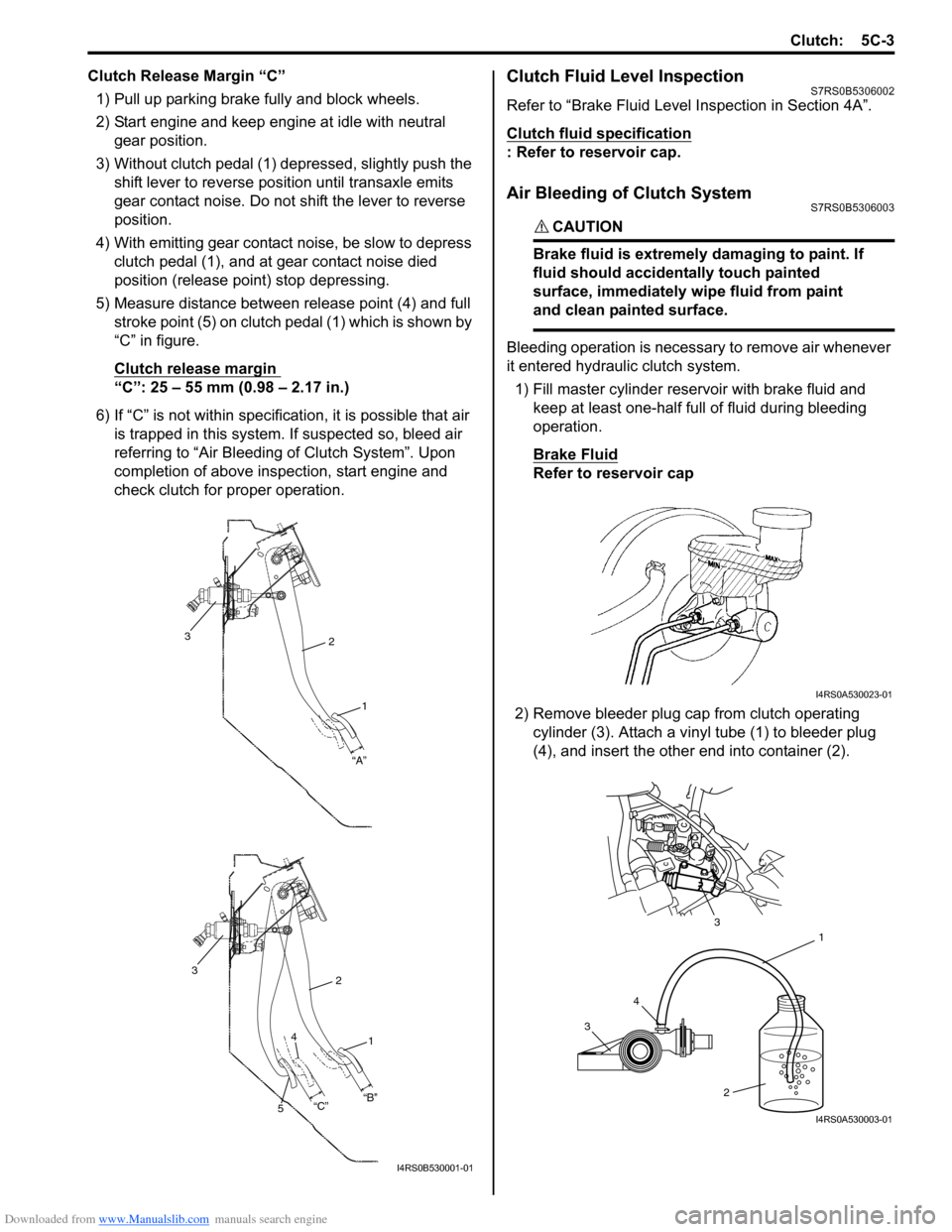
Clutch Release Margin “C”1) Pull up parking brake fully and block wheels.
2) Start engine and keep engine at idle with neutral gear position.
3) Without clutch pedal (1) dep ressed, slightly push the
shift lever to re verse position until transaxle emits
gear contact noise. Do not shift the lever to reverse
position.
4) With emitting gear contact noise, be slow to depress clutch pedal (1), and at gear contact noise died
position (release point) stop depressing.
5) Measure distance between release point (4) and full stroke point (5) on clutch pedal (1) which is shown by
“C” in figure.
Clutch release margin
“C”: 25 – 55 mm (0.98 – 2.17 in.)
6) If “C” is not within specificat ion, it is possible that air
is trapped in this system. If suspected so, bleed air
referring to “Air Bleeding of Clutch System”. Upon
completion of above inspection, start engine and
check clutch for proper operation.
Clutch Fluid Level InspectionS7RS0B5306002
Refer to “Brake Fluid Level Inspection in Section 4A”.
Clutch fluid specification
: Refer to reservoir cap.
Air Bleeding of Clutch SystemS7RS0B5306003
CAUTION!
Brake fluid is extremely damaging to paint. If
fluid should accidentally touch painted
surface, immediately wipe fluid from paint
and clean painted surface.
Bleeding operation is necessary to remove air whenever
it entered hydraulic clutch system.
1) Fill master cylinder reservoir with brake fluid and keep at least one-half full of fluid during bleeding
operation.
Brake Fluid
Refer to reservoir cap
2) Remove bleeder plug cap from clutch operating cylinder (3). Attach a vinyl tube (1) to bleeder plug
(4), and insert the other end into container (2).
2
1
“A”
3
2
1
3
“B”
“C”
4
5
I4RS0B530001-01
I4RS0A530023-01
3 4 1
2
3
I4RS0A530003-01
Page 862 of 1496
Downloaded from www.Manualslib.com manuals search engine 5C-10 Clutch:
3) Aligning clutch disc to flywheel center using special
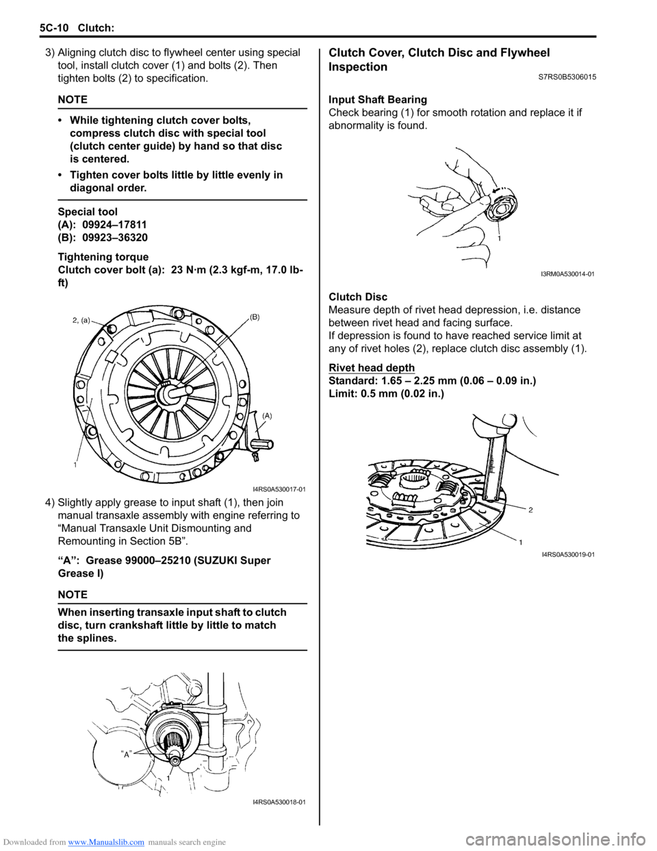
tool, install clutch cover (1) and bolts (2). Then
tighten bolts (2) to specification.
NOTE
• While tightening clutch cover bolts, compress clutch disc with special tool
(clutch center guide) by hand so that disc
is centered.
• Tighten cover bolts little by little evenly in diagonal order.
Special tool
(A): 09924–17811
(B): 09923–36320
Tightening torque
Clutch cover bolt (a): 23 N·m (2.3 kgf-m, 17.0 lb-
ft)
4) Slightly apply grease to input shaft (1), then join manual transaxle assembly with engine referring to
“Manual Transaxle Unit Dismounting and
Remounting in Section 5B”.
“A”: Grease 99000–25210 (SUZUKI Super
Grease I)
NOTE
When inserting transaxle input shaft to clutch
disc, turn crankshaft li ttle by little to match
the splines.
Clutch Cover, Clutch Disc and Flywheel
Inspection
S7RS0B5306015
Input Shaft Bearing
Check bearing (1) for smooth ro tation and replace it if
abnormality is found.
Clutch Disc
Measure depth of rivet head depression, i.e. distance
between rivet head and facing surface.
If depression is found to hav e reached service limit at
any of rivet holes (2), repl ace clutch disc assembly (1).
Rivet head depth
Standard: 1.65 – 2.25 mm (0.06 – 0.09 in.)
Limit: 0.5 mm (0.02 in.)
I4RS0A530017-01
I4RS0A530018-01
I3RM0A530014-01
I4RS0A530019-01
Page 867 of 1496

Downloaded from www.Manualslib.com manuals search engine Table of Contents 6- i
6
Section 6
CONTENTS
Steering
Precautions ................................................. 6-1
Precautions............................................................. 6-1
Precautions on Steering........................................ 6-1
Steering General Diagnosi s.................... 6A-1
Precautions........................................................... 6A-1
Precautions for Steering Diagnosis ..................... 6A-1
Diagnostic Information and Procedures ............ 6A-2 Steering Symptom Diagnosis .............................. 6A-2
Steering Wheel and Column ................... 6B-1
Precautions........................................................... 6B-1
Service Precautions of Steering Wheel and Column.............................................................. 6B-1
General Description ............................................. 6B-1 Steering Wheel and Column Construction .......... 6B-1
Diagnostic Information and Procedures ............ 6B-2 Checking Steering Column for Accident Damage ............................................................ 6B-2
Repair Instructions .............................................. 6B-3 Steering Wheel and Column Construction .......... 6B-3
Steering Wheel Removal and Installation ........... 6B-4
Contact Coil Cable Assembly Removal and Installation ......................................................... 6B-5
Centering Contact Coil Cable Assembly ............. 6B-6
Contact Coil Cable Assembly Inspection ............ 6B-6
Steering Angle Sensor Removal and Installation ......................................................... 6B-6
Steering Angle Sensor Inspection ....................... 6B-6
Steering Column Removal and Installation ......... 6B-7
Steering Column Inspecti on ................................ 6B-8
Ignition Switch Cylinder Assembly Removal and Installation (Non- Keyless Start Model)...... 6B-9
Steering Lock Assembly (Ignition Switch) Removal and Installation................................... 6B-9
Steering Lower Shaft Removal and Installation ....................................................... 6B-10
Specifications ..................................................... 6B-11
Tightening Torque Specifications ...................... 6B-11
Special Tools and Equipmen t ........................... 6B-11
Special Tool ...................................................... 6B-11
Power Assisted Steering System........... 6C-1
Precautions........................................................... 6C-1 Steering System Note .........................................6C-1
Precautions in Diagnosing Troubles ...................6C-1
General Description .............................................6C-2 P/S System Description ......................................6C-2
EPS Diagnosis General Descr iption ...................6C-3
On-Board Diagnostic System Description ...........6C-3
Schematic and Routing Diagram ........................6C-4 EPS System Wiring Circuit Diagram ...................6C-4
Diagnostic Information and Procedures ............6C-5 EPS System Check .............. ...............................6C-5
“EPS” Warning Light Check . ...............................6C-8
DTC Check..........................................................6C-8
DTC Clearance ...................................................6C-9
DTC Table ...........................................................6C-9
Scan Tool Data .................................................6C-11
Visual Inspection ...............................................6C-12
P/S System Symptom Diagnosis ......................6C-12
Serial Data Link Circuit Check ..........................6C-13
“EPS” Warning Light Do es Not Come ON with
Ignition Switch Turn ed ON before Engine
Starts ...............................................................6C-15
“EPS” Warning Light Remains ON Steady after Engine Starts ..........................................6C-16
DTC C1113: Steering Torque Sensor (Main and Sub) Circuit Correlation ............................6C-17
DTC C1114: Steering Torque Sensor Reference Power Supply Circuit .....................6C-19
DTC C1117: Steering Torque Sensor Failure Signal Circuit Low ...........................................6C-21
DTC C1118: Steering Torque Sensor Failure Signal Circuit High...........................................6C-22
DTC C1119: Steering Torque Sensor Power Supply Circuit ..................................................6C-24
DTC C1121 / C1123 / C1124: VSS Circuit
Failure .............................................................6C-26
DTC C1122: Engine Speed Signal....................6C-28
DTC C1141 / C1142 / C1143 / C1145: P/S Motor Circuit Failure ........................................6C-30
DTC C1153: P/S Control Module Power Supply Circuit Voltage Low .............................6C-32
DTC C1155: P/S Control Module Failure ..........6C-33
P/S Control Module Power Supply and Ground Circuit Check ......................................6C-34
Inspection of P/S Control Module and Its Circuits ............................................................6C-35
Page 874 of 1496
Downloaded from www.Manualslib.com manuals search engine 6B-3 Steering Wheel and Column:
Repair Instructions
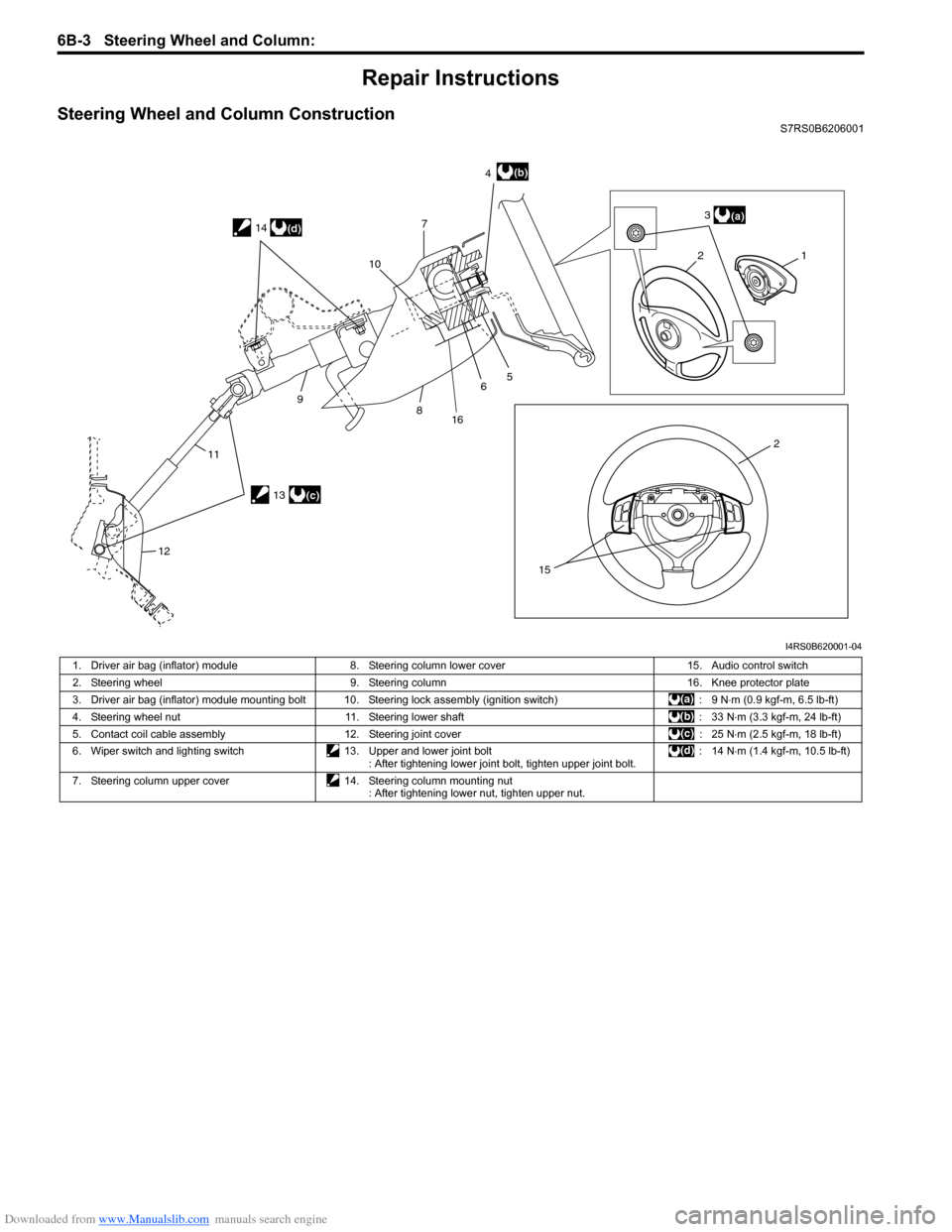
Steering Wheel and Column ConstructionS7RS0B6206001
21
2 3
4
7
5
6
8
9
11
12 10
15
(a)
(b)
13(c)
14
(d)
16
I4RS0B620001-04
1. Driver air bag (inflator) module
8. Steering column lower cover 15. Audio control switch
2. Steering wheel 9. Steering column 16. Knee protector plate
3. Driver air bag (inflator) module mounting bolt 10. Steering lock assembly (ignition switch) : 9 N⋅m (0.9 kgf-m, 6.5 lb-ft)
4. Steering wheel nut 11. Steering lower shaft : 33 N⋅m (3.3 kgf-m, 24 lb-ft)
5. Contact coil cable assembly 12. Steering joint cover : 25 N⋅m (2.5 kgf-m, 18 lb-ft)
6. Wiper switch and lighting switch 13. Upper and lower joint bolt
: After tightening lower joint bolt, tighten upper joint bolt. : 14 N
⋅m (1.4 kgf-m, 10.5 lb-ft)
7. Steering column upper cover 14. Steering column mounting nut
: After tightening lower nut, tighten upper nut.
Page 877 of 1496
Downloaded from www.Manualslib.com manuals search engine Steering Wheel and Column: 6B-6
Centering Contact Coil Cable AssemblyS7RS0B6206004
1) Check that vehicle’s wheels (front tires) are set at straight-ahead position.
2) Check that ignition swit ch is at LOCK position.
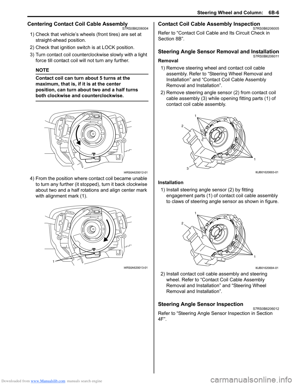
3) Turn contact coil counterclockwise slowly with a light force till contact coil will not turn any further.
NOTE
Contact coil can turn about 5 turns at the
maximum, that is, if it is at the center
position, can turn about two and a half turns
both clockwise and counterclockwise.
4) From the position where contact coil became unable to turn any further (it stopped), turn it back clockwise
about two and a half rotations and align center mark
with alignment mark (1).
Contact Coil Cable Assembly InspectionS7RS0B6206005
Refer to “Contact Coil Cable and Its Circuit Check in
Section 8B”.
Steering Angle Sensor Removal and InstallationS7RS0B6206011
Removal
1) Remove steering wheel and contact coil cable assembly. Refer to “Ste ering Wheel Removal and
Installation” and “Contact Coil Cable Assembly
Removal and Installation”.
2) Remove steering angle sensor (2) from contact coil cable assembly (3) while op ening fitting parts (1) of
contact coil cable assembly.
Installation 1) Install steering angle sensor (2) by fitting engagement parts (1) of contact coil cable assembly
to claws of steering angle sensor as shown in figure.
2) Install contact coil cable assembly and steering wheel. Refer to “Contact Coil Cable Assembly
Removal and Installation” and “Steering Wheel
Removal and Installation”.
Steering Angle Sensor InspectionS7RS0B6206012
Refer to “Steering Angle Sens or Inspection in Section
4F”.
I4RS0A620012-01
1
I4RS0A620013-01
1
1
2
3I6JB01620003-01
1
1
2
I6JB01620004-01
Page 878 of 1496
Downloaded from www.Manualslib.com manuals search engine 6B-7 Steering Wheel and Column:
Steering Column Removal and InstallationS7RS0B6206006
CAUTION!
Once the steering column is removed from
the vehicle, the column is extremely
susceptible to damage.
• Dropping the column assembly on its end could collapse the steering shaft or loosen
the plastic shear pins which maintain
column length.
• Leaning on the column assembly could cause it to bend or deform.
Any of the damage could impair the column’s
collapsible design.
Steering column mounting nuts should not
be loosened with steering shaft joint upper
side bolt tightened as this could cause
damage to shaft joint bearing.
NOTE
When servicing steering column or any
column-mounted component, remove
steering wheel. But when removing steering
column simply to gain access to instrument
panel components, leave steering wheel
installed on steering column.
Removal
WARNING!
Never rest a steering column assembly on
the steering wheel with the air bag (inflator)
module face down and column vertical.
Otherwise, personal injury may result.
1) Disconnect negative (–) cable at battery.
2) Disable air bag system. Re fer to “Disabling Air Bag
System in Section 8B”.
3) Remove steering wheel and contact coil cable assembly referring to “S teering Wheel Removal and
Installation” and “Contact Coil Cable Assembly
Removal and Installation”.
4) Detach lighting switch and wiper switch from steering column.
5) Remove immobilizer cont rol module from steering
column, referring to “Immo bilizer Control Module
(ICM) Removal and Installation in Section 10C”.
6) Remove steering column hole cover.
7) Remove steering joint cover.
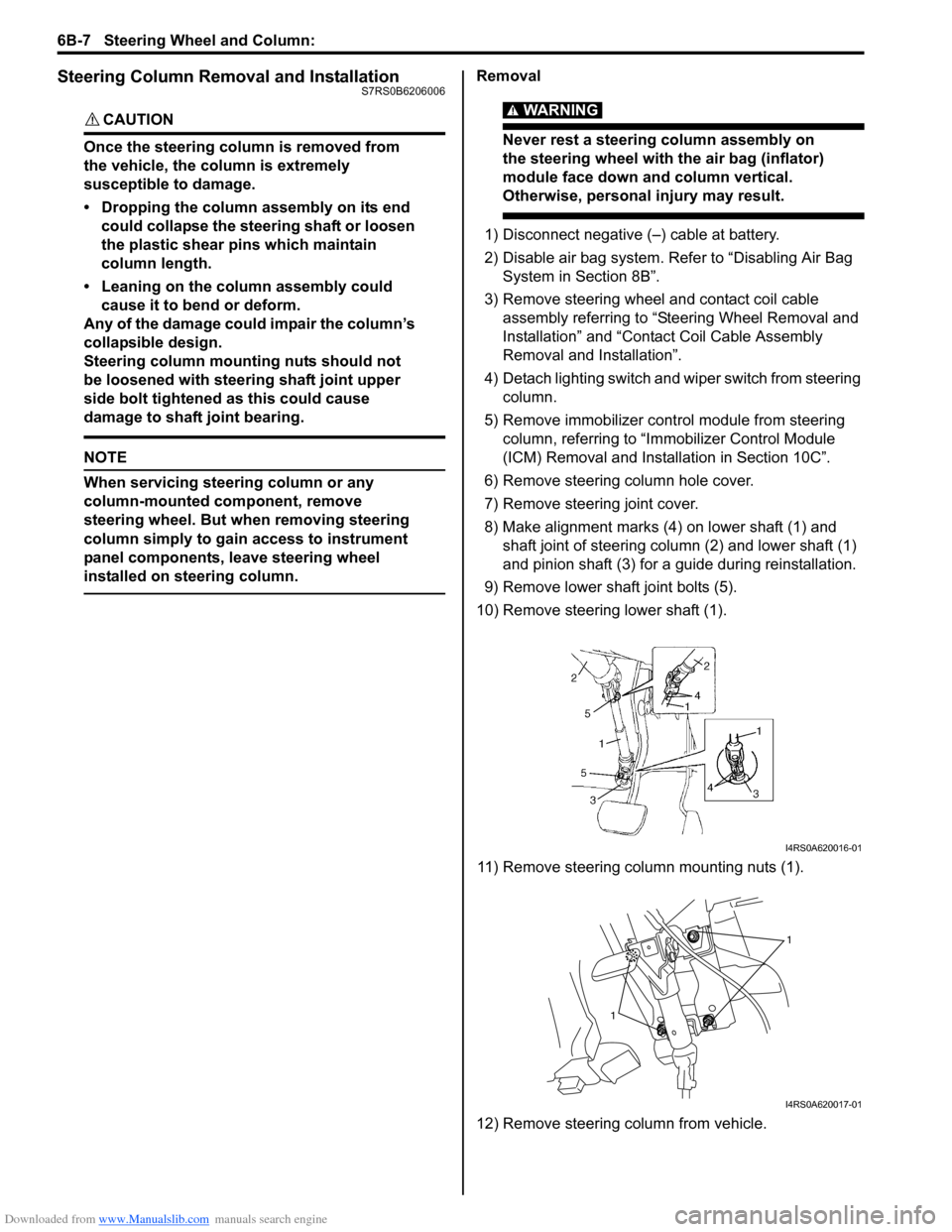
8) Make alignment marks (4) on lower shaft (1) and shaft joint of steering column (2) and lower shaft (1)
and pinion shaft (3) for a guide during reinstallation.
9) Remove lower shaf t joint bolts (5).
10) Remove steering lower shaft (1).
11) Remove steering column mounting nuts (1).
12) Remove steering column from vehicle.
I4RS0A620016-01
1
1
I4RS0A620017-01
Page 879 of 1496
Downloaded from www.Manualslib.com manuals search engine Steering Wheel and Column: 6B-8
Installation
CAUTION!
After tightening steering column mounting
nuts, shaft joint bolts should be tightened.
Wrong tightening order could cause a
damage to shaft joint.
1) Be sure that front wheels are in straight.
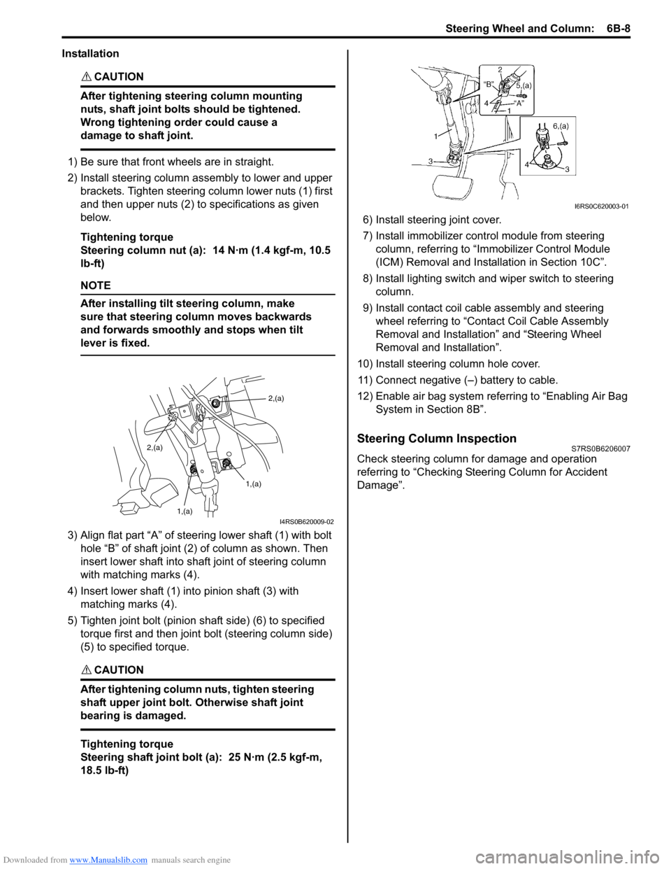
2) Install steering column assembly to lower and upper brackets. Tighten steering column lower nuts (1) first
and then upper nuts (2) to specifications as given
below.
Tightening torque
Steering column nut (a): 14 N·m (1.4 kgf-m, 10.5
lb-ft)
NOTE
After installing tilt steering column, make
sure that steering column moves backwards
and forwards smoothly and stops when tilt
lever is fixed.
3) Align flat part “A” of stee ring lower shaft (1) with bolt
hole “B” of shaft joint (2) of column as shown. Then
insert lower shaft into shaf t joint of steering column
with matching marks (4).
4) Insert lower shaft (1) into pinion shaft (3) with matching marks (4).
5) Tighten joint bolt (pinion shaft side) (6) to specified torque first and then joint bolt (steering column side)
(5) to specified torque.
CAUTION!
After tightening column nuts, tighten steering
shaft upper joint bolt. Otherwise shaft joint
bearing is damaged.
Tightening torque
Steering shaft joint bolt (a): 25 N·m (2.5 kgf-m,
18.5 lb-ft) 6) Install steering joint cover.
7) Install immobilizer cont
rol module from steering
column, referring to “Immo bilizer Control Module
(ICM) Removal and Installation in Section 10C”.
8) Install lighting switch and wiper switch to steering column.
9) Install contact coil cable assembly and steering wheel referring to “Conta ct Coil Cable Assembly
Removal and Installation” and “Steering Wheel
Removal and Installation”.
10) Install steering column hole cover. 11) Connect negative (–) battery to cable.
12) Enable air bag system refe rring to “Enabling Air Bag
System in Section 8B”.
Steering Column InspectionS7RS0B6206007
Check steering column for damage and operation
referring to “Checking Steering Column for Accident
Damage”.
2,(a)
1,(a)
1,(a)
2,(a)
I4RS0B620009-02
I6RS0C620003-01
Page 885 of 1496
Downloaded from www.Manualslib.com manuals search engine Power Assisted Steering System: 6C-3
EPS Diagnosis General DescriptionS7RS0B6301002
The P/S system in this vehicle is controlled by the P/S control module. T he P/S control module has an on-board
diagnostic system which detects a malfunction in this system. When diagnosing troubles, be sure to have full
understanding of the outline of “On-Board Diagnostic Sy stem Description” and each item in “Precautions in
Diagnosing Troubles”, and then execute diagnosis according to “EPS System Check”.
On-Board Diagnostic System DescriptionS7RS0B6301003
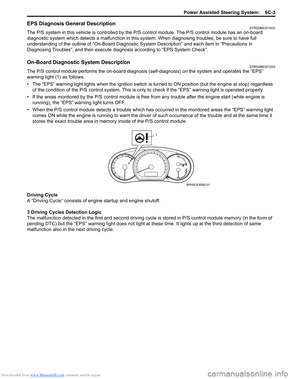
The P/S control module performs the on -board diagnosis (self-diagnosis) on the system and operates the “EPS”
warning light (1) as follows.
• The “EPS” warning light lights when the ignition switch is turned to ON position (but the engine at stop) regardless
of the condition of the P/S co ntrol system. This is only to check if the “EPS” warning light is operated properly.
• If the areas monitored by the P/S control module is free from any trouble after the engine start (while engine is
running), the “EPS” warning light turns OFF.
• When the P/S control module detects a trouble which has occurred in th e monitored areas the “EPS” warning light
comes ON while the engine is running to warn the driver of such occurrence of the trouble and at the same time it
stores the exact trouble area in memory inside of the P/S control module.
Driving Cycle
A “Driving Cycle” consists of en gine startup and engine shutoff.
3 Driving Cycles Detection Logic
The malfunction detected in the first and second driving cycl e is stored in P/S control module memory (in the form of
pending DTC) but the “EPS” wa rning light does not light at these time. It lights up at t he third detection of same
malfunction also in the next driving cycle.
1
I6RS0C630002-01
Page 886 of 1496
Downloaded from www.Manualslib.com manuals search engine 6C-4 Power Assisted Steering System:
Schematic and Routing Diagram
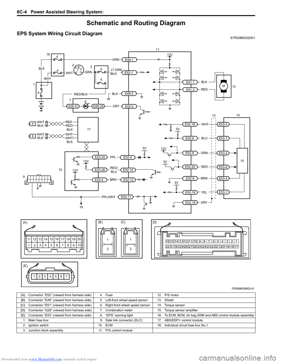
EPS System Wiring Circuit DiagramS7RS0B6302001
M
5V
BRNRED/
BLU
BLK
RED
WHT
BLU
GRN
BRN YEL
E52-11
E52-14E52-12
E23-4
E23-26
E23-25 E51-1
E51-2
E52-18
E53-5
E53-7
E52-6
E52-8
E53-2
E52-9
E52-16
E52-19
GRY
PPL/WHT
[A ]
[E ]
12 3
4 5 67
89
11
10
12 13
141516
17 18 19 20
1
2
[B ][C ]
1210 9 8 7654 3 21
16 15 14 13 12 11
26 25 24 2322 21 20 19 18 17
32 31 30 29 28 27
[D]
5V
PPL
E52-4
11
12
13 14
15
10
9
16
12V
5V
5V
12V
REDE52-20E53-6
E53-4
E53-1
7654321
5
REDRED/
BLKWHT
6WHTWHT/BLKWHTBLK
12V
12V
17BLK
GRY
LT GRN
/BLK
E52-1
E52-5
E49-1
GRNGRNWHTBLK
WHY
G28-25G28-31
RED/BLK
18
3
4
4
7 8
4
4
1 2
4
E49-2BLK
I7RS0B630002-01
[A]: Connector “E52” (viewed from harness side) 4. Fuse 12. P/S motor
[B]: Connector “E49” (viewed from harness side ) 5. Left-front wheel speed sensor 13. Shield
[C]: Connector “E51” (viewed from harness side) 6 . Right-front wheel speed sensor 14. Torque sensor
[D]: Connector “G28” (viewed from harness side) 7. Combination meter 15. Torque sensor amplifier
[E]: Connector “E53” (viewed from harness side) 8. “EPS” warning light16. To ECM, BCM, Air bag SDM and ABS control module assembly
1. Main fuse box 9. Date link connector (DLC) 17. ABS/ESP ® control module
2. Ignition switch 10. ECM18. Individual circuit fuse box No.1
3. Junction block assembly 11. P/S control module
Page 887 of 1496
Downloaded from www.Manualslib.com manuals search engine Power Assisted Steering System: 6C-5
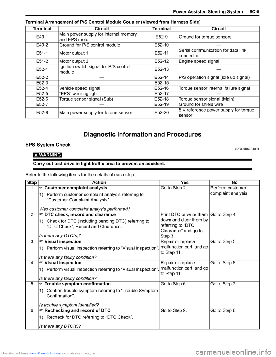
Terminal Arrangement of P/S Control Module Coupler (Viewed from Harness Side)
Diagnostic Information and Procedures
EPS System CheckS7RS0B6304001
WARNING!
Carry out test drive in light traffic area to prevent an accident.
Refer to the following items for the details of each step.Terminal Circuit Terminal Circuit
E49-1 Main power supply for internal memory
and EPS motor E52-9 Ground for torque sensors
E49-2 Ground for P/S control module E52-10 —
E51-1 Motor output 1 E52-11 Serial communication for data link
connector
E51-2 Motor output 2 E52-12 Engine speed signal
E52-1 Ignition switch signal for P/S control
module E52-13 —
E52-2 — E52-14 P/S operation signal (idle up signal)
E52-3 — E52-15 —
E52-4 Vehicle speed signal E52-16 Torque sensor internal failure signal
E52-5 “EPS” warning light E52-17 —
E52-6 Torque sensor signal (Sub) E52-18 Torque sensor signal (Main)
E52-7 — E52-19 Ground for shield wire
E52-8 Main power supply for torque sensor E52-20 5 V reference power supply for torque
sensor
Step
Action YesNo
1 �) Customer complaint analysis
1) Perform customer complaint analysis referring to “Customer Complaint Analysis”.
Was customer complaint analysis performed? Go to Step 2.
Perform customer
complaint analysis.
2 �) DTC check, record and clearance
1) Check for DTC (including pending DTC) referring to “DTC Check”, Record and Clearance.
Is there any DTC(s)? Print DTC or write them
down and clear them by
referring to “DTC
Clearance” and go to
St ep 3 .Go to Step 4.
3 �) Visual inspection
1) Perform visual inspection referring to “Visual Inspection”.
Is there any faulty condition? Repair or replace
malfunction part, and go
to Step 11.
Go to Step 5.
4 �) Visual inspection
1) Perform visual inspection referring to “Visual Inspection”.
Is there any faulty condition? Repair or replace
malfunction part, and go
to Step 11.
Go to Step 8.
5 �) Trouble symptom confirmation
1) Confirm trouble symptom referring to “Trouble Symptom Confirmation”.
Is trouble symptom identified? Go to Step 6.
Go to Step 7.
6 �) Rechecking and record of DTC
1) Recheck for DTC referring to “DTC Check”.
Is there any DTC(s)? Go to Step 9.
Go to Step 8.