10b SUZUKI SWIFT 2008 2.G Service User Guide
[x] Cancel search | Manufacturer: SUZUKI, Model Year: 2008, Model line: SWIFT, Model: SUZUKI SWIFT 2008 2.GPages: 1496, PDF Size: 34.44 MB
Page 1013 of 1496
Downloaded from www.Manualslib.com manuals search engine Air Conditioning System: Automatic Type 7B-65
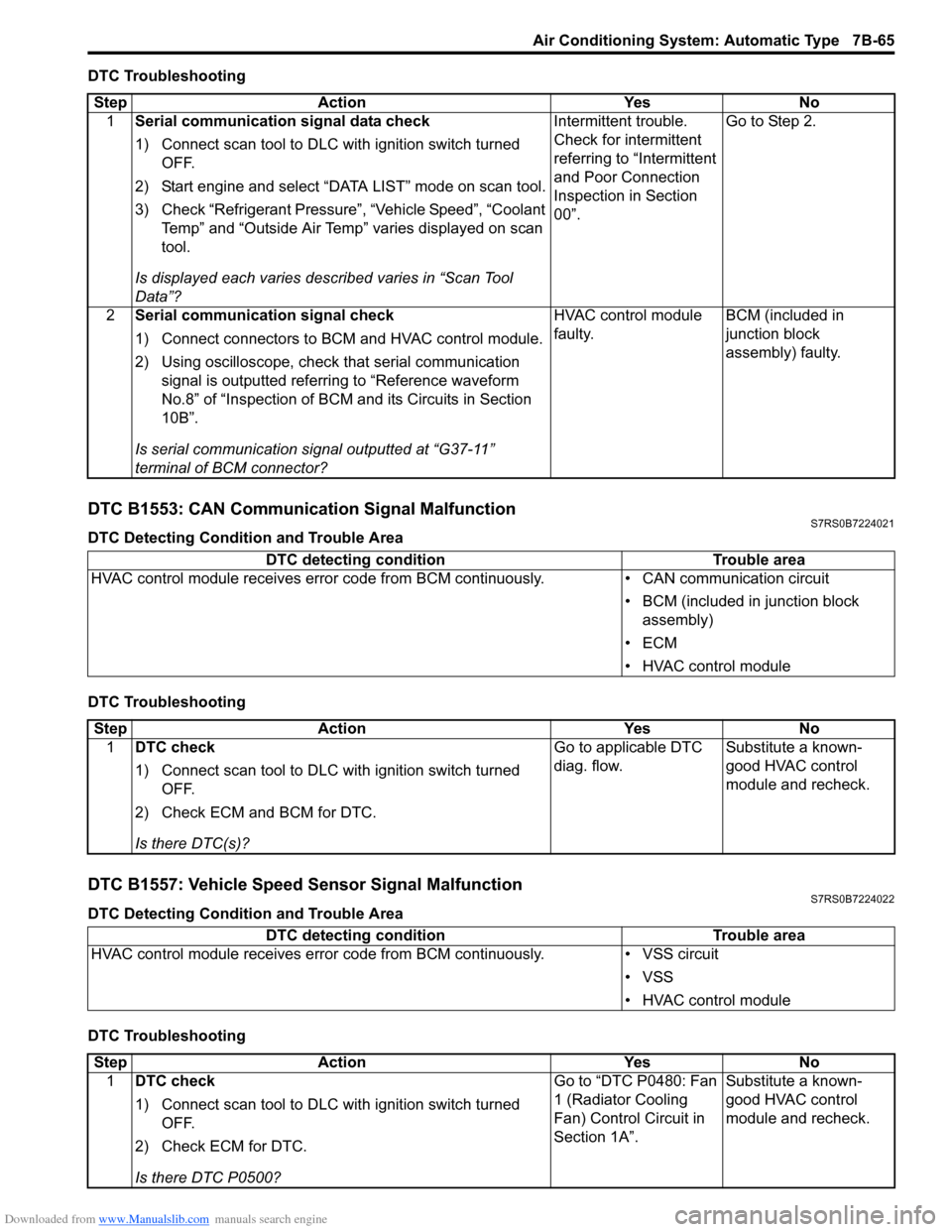
DTC Troubleshooting
DTC B1553: CAN Communication Signal MalfunctionS7RS0B7224021
DTC Detecting Condition and Trouble Area
DTC Troubleshooting
DTC B1557: Vehicle Speed Sensor Signal MalfunctionS7RS0B7224022
DTC Detecting Condition and Trouble Area
DTC TroubleshootingStep Action Yes No
1 Serial communication signal data check
1) Connect scan tool to DLC with ignition switch turned
OFF.
2) Start engine and select “DATA LIST” mode on scan tool.
3) Check “Refrigerant Pressure”, “Vehicle Speed”, “Coolant Temp” and “Outside Air Temp” varies displayed on scan
tool.
Is displayed each va ries described varies in “Scan Tool
Data”? Intermittent trouble.
Check for intermittent
referring to “Intermittent
and Poor Connection
Inspection in Section
00”.
Go to Step 2.
2 Serial communication signal check
1) Connect connectors to BCM and HVAC control module.
2) Using oscilloscope, check that serial communication
signal is outputted referring to “Reference waveform
No.8” of “Inspection of BCM and its Circuits in Section
10B”.
Is serial communication signal outputted at “G37-11”
terminal of BCM connector? HVAC control module
faulty.
BCM (included in
junction block
assembly) faulty.
DTC detecting condition
Trouble area
HVAC control module receives error code fr om BCM continuously.• CAN communication circuit
• BCM (included in junction block assembly)
•ECM
• HVAC control module
Step Action YesNo
1 DTC check
1) Connect scan tool to DLC with ignition switch turned
OFF.
2) Check ECM and BCM for DTC.
Is there DTC(s)? Go to applicable DTC
diag. flow.
Substitute a known-
good HVAC control
module and recheck.
DTC detecting condition
Trouble area
HVAC control module receives error code from BCM continuously. • VSS circuit
• VSS
• HVAC control module
Step Action YesNo
1 DTC check
1) Connect scan tool to DLC with ignition switch turned
OFF.
2) Check ECM for DTC.
Is there DTC P0500? Go to “DTC P0480: Fan
1 (Radiator Cooling
Fan) Control Circuit in
Section 1A”.
Substitute a known-
good HVAC control
module and recheck.
Page 1015 of 1496
Downloaded from www.Manualslib.com manuals search engine Air Conditioning System: Automatic Type 7B-67
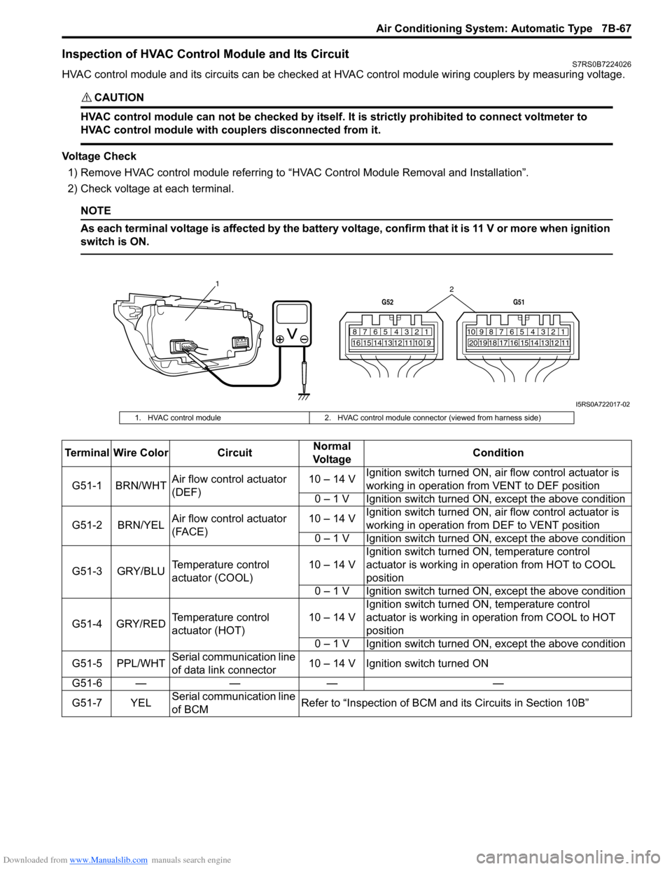
Inspection of HVAC Control Module and Its CircuitS7RS0B7224026
HVAC control module and its circuits can be checked at HVAC control module wiring couplers by measuring voltage.
CAUTION!
HVAC control module can not be checked by itself. It is strictly prohibited to connect voltmeter to
HVAC control module with couplers disconnected from it.
Voltage Check
1) Remove HVAC control module referring to “HVAC Control Module Removal and Installation”.
2) Check voltage at each terminal.
NOTE
As each terminal voltage is affected by the battery voltage, confirm that it is 11 V or more when ignition
switch is ON.
7812910
65 431516 14 13 12 11
G52
789101920121112
65 431718 16 15 14 13
G51
1
2
I5RS0A722017-02
1. HVAC control module2. HVAC control module connector (viewed from harness side)
Terminal Wire Color CircuitNormal
Vo l ta g e Condition
G51-1 BRN/WHT Air flow control actuator
(DEF) 10 – 14 V
Ignition switch turned ON, ai
r flow control actuator is
working in operation fr om VENT to DEF position
0 – 1 V Ignition switch turned ON, except the above condition
G51-2 BRN/YEL Air flow control actuator
(FACE) 10 – 14 V
Ignition switch turned ON, ai
r flow control actuator is
working in operation fr om DEF to VENT position
0 – 1 V Ignition switch turned ON, except the above condition
G51-3 GRY/BLU Temperature control
actuator (COOL) 10 – 14 VIgnition switch turned ON, temperature control
actuator is working in ope
ration from HOT to COOL
position
0 – 1 V Ignition switch turned ON, except the above condition
G51-4 GRY/RED Temperature control
actuator (HOT) 10 – 14 VIgnition switch turned ON, temperature control
actuator is working in operation from COOL to HOT
position
0 – 1 V Ignition switch turned ON, except the above condition
G51-5 PPL/WHT Serial communication line
of data link connector 10 – 14 V Ignition switch turned ON
G51-6 — — — —
G51-7 YEL Serial communication line
of BCM Refer to “Inspection of BCM a
nd its Circuits in Section 10B”
Page 1016 of 1496
Downloaded from www.Manualslib.com manuals search engine 7B-68 Air Conditioning System: Automatic Type
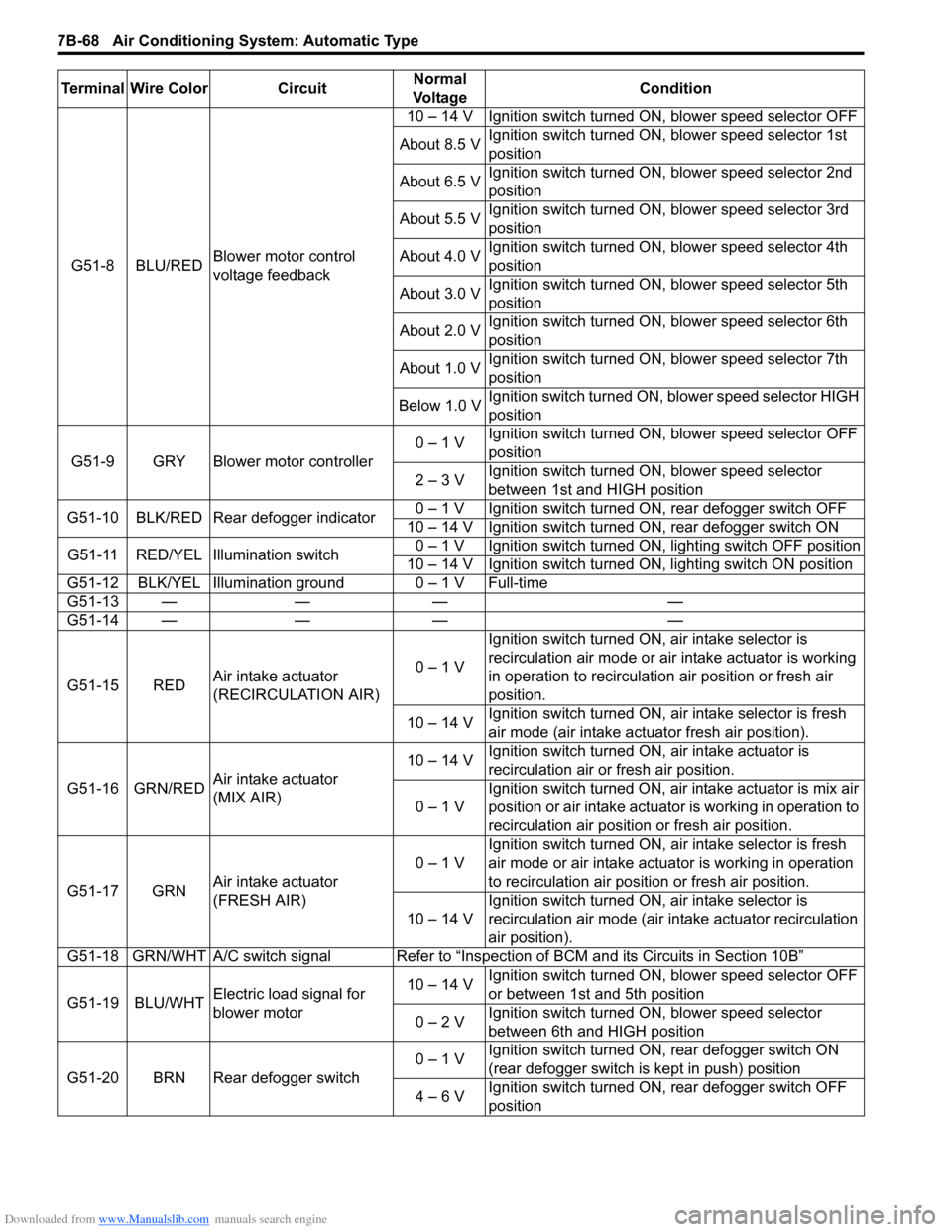
G51-8 BLU/REDBlower motor control
voltage feedback 10 – 14 V Ignition switch turned ON, blower speed selector OFF
About 8.5 V Ignition switch turned ON, blower speed selector 1st
position
About 6.5 V Ignition switch turned ON, blower speed selector 2nd
position
About 5.5 V Ignition switch turned ON, blower speed selector 3rd
position
About 4.0 V Ignition switch turned ON, blower speed selector 4th
position
About 3.0 V Ignition switch turned ON, blower speed selector 5th
position
About 2.0 V Ignition switch turned ON, blower speed selector 6th
position
About 1.0 V Ignition switch turned ON, blower speed selector 7th
position
Below 1.0 V Ignition switch turned ON, blower speed selector HIGH
position
G51-9 GRY Blower motor controller 0 – 1 V
Ignition switch turned ON, blower speed selector OFF
position
2 – 3 V Ignition switch turned ON, blower speed selector
between 1st and HIGH position
G51-10 BLK/RED Rear defogger indicator 0 – 1 V Ignition switch turned ON, rear defogger switch OFF
10 – 14 V Ignition switch turned ON, rear defogger switch ON
G51-11 RED/YEL Illumination switch 0 – 1 V Ignition switch turned ON, lighting switch OFF position
10 – 14 V Ignition switch turned ON, lighting switch ON position
G51-12 BLK/YEL Illumination ground 0 – 1 V Full-time
G51-13 — — — —
G51-14 — — — —
G51-15 RED Air intake actuator
(RECIRCULATION AIR) 0 – 1 VIgnition switch turned ON, air intake selector is
recirculation air mode or air intake actuator is working
in operation to recirculation air position or fresh air
position.
10 – 14 V Ignition switch turned ON, ai
r intake selector is fresh
air mode (air intake actuator fresh air position).
G51-16 GRN/RED Air intake actuator
(MIX AIR) 10 – 14 V
Ignition switch turned ON, air intake actuator is
recirculation air or fresh air position.
0 – 1 V Ignition switch turned ON, air intake actuator is mix air
position or air intake actuator is working in operation to
recirculation air position or fresh air position.
G51-17 GRN Air intake actuator
(FRESH AIR) 0 – 1 V
Ignition switch turned ON, ai
r intake selector is fresh
air mode or air intake actuator is working in operation
to recirculation air position or fresh air position.
10 – 14 V Ignition switch turned ON, air intake selector is
recirculation air mode (air intake actuator recirculation
air position).
G51-18 GRN/WHT A/C switch signal Refer to “Inspe ction of BCM and its Circuits in Section 10B”
G51-19 BLU/WHT Electric load signal for
blower motor 10 – 14 V
Ignition switch turned ON, blower speed selector OFF
or between 1st and 5th position
0 – 2 V Ignition switch turned ON, blower speed selector
between 6th and HIGH position
G51-20 BRN Rear defogger switch 0 – 1 V
Ignition switch turned ON, rear defogger switch ON
(rear defogger switch is kept in push) position
4 – 6 V Ignition switch turned ON, rear defogger switch OFF
position
Terminal Wire Color Circuit
Normal
Vo l ta g e Condition
Page 1060 of 1496
Downloaded from www.Manualslib.com manuals search engine 8B-22 Air Bag System:
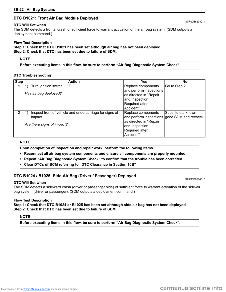
DTC B1021: Front Air Bag Module DeployedS7RS0B8204014
DTC Will Set when
The SDM detects a frontal crash of sufficient force to warrant activation of the air bag system. (SDM outputs a
deployment command.)
Flow Test Description
Step 1: Check that DTC B1021 has been set although air bag has not been deployed.
Step 2: Check that DTC has been set due to failure of SDM.
NOTE
Before executing items in this flow, be sure to perform “Air Bag Diagnostic System Check”.
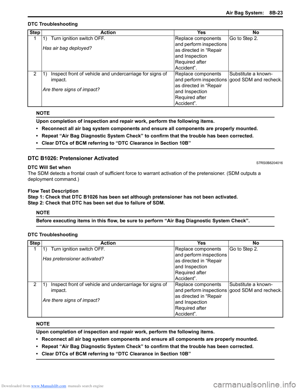
DTC Troubleshooting
NOTE
Upon completion of inspection and repair work, perform the following items.
• Reconnect all air bag system components and ensure all components are properly mounted.
• Repeat “Air Bag Diagnostic System Check” to confirm that the trouble has been corrected.
• Clear DTCs of BCM referring to “DTC Clearance in Section 10B”
DTC B1024 / B1025: Side-Air Bag (Driver / Passenger) DeployedS7RS0B8204015
DTC Will Set when
The SDM detects a sideward crash (driver or passenger side) of sufficient force to warrant activation of the side-air
bag system (driver or pa ssenger). (SDM outputs a deployment command.)
Flow Test Description
Step 1: Check that DTC B1024 or B1025 has been set although side-air bag has not been deployed.
Step 2: Check that DTC has been set due to failure of SDM.
NOTE
Before executing items in this flow, be sure to perform “Air Bag Diagnostic System Check”.
Step Action YesNo
1 1) Turn ignition switch OFF.
Has air bag deployed? Replace components
and perform inspections
as directed in “Repair
and Inspection
Required after
Accident”.Go to Step 2.
2 1) Inspect front of vehicle and undercarriage for signs of impact.
Are there signs of impact? Replace components
and perform inspections
as directed in “Repair
and Inspection
Required after
Accident”.Substitute a known-
good SDM and recheck.
Page 1061 of 1496
Downloaded from www.Manualslib.com manuals search engine Air Bag System: 8B-23
DTC Troubleshooting
NOTE
Upon completion of inspection and repair work, perform the following items.
• Reconnect all air bag system components and ensure all components are properly mounted.
• Repeat “Air Bag Diagnostic System Check” to confirm that the trouble has been corrected.
• Clear DTCs of BCM referring to “DTC Clearance in Section 10B”
DTC B1026: Pretensioner ActivatedS7RS0B8204016
DTC Will Set when
The SDM detects a frontal crash of sufficient force to warrant activation of the pr etensioner. (SDM outputs a
deployment command.)
Flow Test Description
Step 1: Check that DTC B1026 has been set although pretensioner has not been activated.
Step 2: Check that DTC has been set due to failure of SDM.
NOTE
Before executing items in this flow, be sure to perform “Air Bag Diagnostic System Check”.
DTC Troubleshooting
NOTE
Upon completion of inspection and repair work, perform the following items.
• Reconnect all air bag system components and ensure all components are properly mounted.
• Repeat “Air Bag Diagnostic System Check” to confirm that the trouble has been corrected.
• Clear DTCs of BCM referring to “DTC Clearance in Section 10B”
StepAction YesNo
1 1) Turn ignition switch OFF.
Has air bag deployed? Replace components
and perform inspections
as directed in “Repair
and Inspection
Required after
Accident”.Go to Step 2.
2 1) Inspect front of vehicle and undercarriage for signs of impact.
Are there signs of impact? Replace components
and perform inspections
as directed in “Repair
and Inspection
Required after
Accident”.Substitute a known-
good SDM and recheck.
Step
Action YesNo
1 1) Turn ignition switch OFF.
Has pretensioner activated? Replace components
and perform inspections
as directed in “Repair
and Inspection
Required after
Accident”.Go to Step 2.
2 1) Inspect front of vehicle and undercarriage for signs of impact.
Are there signs of impact? Replace components
and perform inspections
as directed in “Repair
and Inspection
Required after
Accident”.Substitute a known-
good SDM and recheck.
Page 1235 of 1496
Downloaded from www.Manualslib.com manuals search engine Wiring Systems: 9A-64
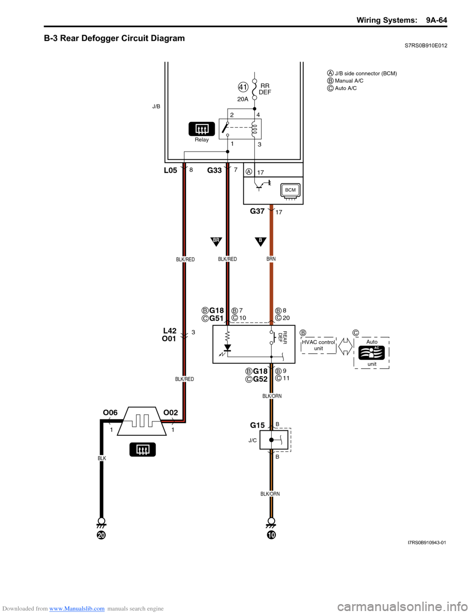
B-3 Rear Defogger Circuit DiagramS7RS0B910E012
L42
O013
BLK/RED
O02
1
O06
1
20
1
2
4
3
20A RR
DEF
41
Relay
17
BRN
G3717
G337
BLK/REDBLK/RED
L058
REAR DEF
HVAC control
unit
BLK/ORN
10
BLK/ORN
G15
J/C B
B
BLK
G18
G51
J/B
B
A
BR
J/B side connector (BCM)
Manual A/C
Auto A/C
ABC
BCM
BB
C
G18
G52B
C
C7
10B
B
C8
20
BC9
11
C
Auto
unit
I7RS0B910943-01
Page 1285 of 1496
Downloaded from www.Manualslib.com manuals search engine Lighting Systems: 9B-3
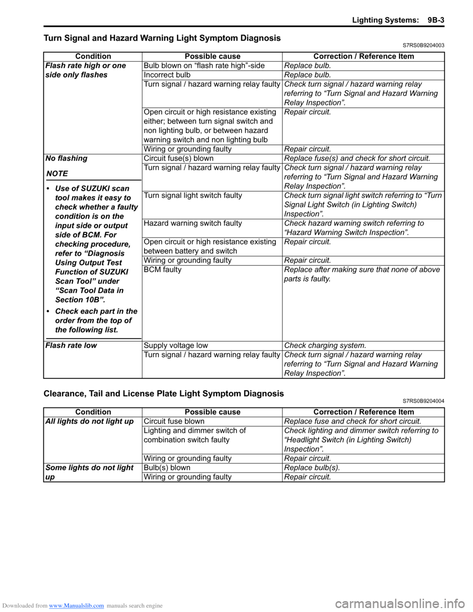
Turn Signal and Hazard Warning Light Symptom DiagnosisS7RS0B9204003
Clearance, Tail and License Plate Light Symptom DiagnosisS7RS0B9204004
ConditionPossible cause Correction / Reference Item
Flash rate high or one
side only flashes Bulb blown on “flash rate high”-side
Replace bulb.
Incorrect bulb Replace bulb.
Turn signal / hazard warning relay faulty Check turn signal / hazard warning relay
referring to “Turn Signal and Hazard Warning
Relay Inspection”.
Open circuit or high resistance existing
either; between turn signal switch and
non lighting bulb, or between hazard
warning switch and non lighting bulb Repair circuit.
Wiring or grounding faulty Repair circuit.
No flashing
NOTE
• Use of SUZUKI scan tool makes it easy to
check whether a faulty
condition is on the
input side or output
side of BCM. For
checking procedure,
refer to “Diagnosis
Using Output Test
Function of SUZUKI
Scan Tool” under
“Scan Tool Data in
Section 10B”.
• Check each part in the order from the top of
the following list.
Circuit fuse(s) blown Replace fuse(s) and check for short circuit.
Turn signal / hazard warning relay faulty Check turn signal / hazard warning relay
referring to “Turn Signal and Hazard Warning
Relay Inspection”.
Turn signal light switch faulty Check turn signal light switch referring to “Turn
Signal Light Switch (in Lighting Switch)
Inspection”.
Hazard warning switch faulty Check hazard warning switch referring to
“Hazard Warning Switch Inspection”.
Open circuit or high resistance existing
between battery and switch Repair circuit.
Wiring or grounding faulty Repair circuit.
BCM faulty Replace after making sure that none of above
parts is faulty.
Flash rate low Supply voltage low Check charging system.
Turn signal / hazard warning relay faulty Check turn signal / hazard warning relay
referring to “Turn Signal and Hazard Warning
Relay Inspection”.
ConditionPossible cause Correction / Reference Item
All lights do not light up Circuit fuse blown Replace fuse and check for short circuit.
Lighting and dimmer switch of
combination switch faulty Check lighting and dimmer switch referring to
“Headlight Switch (in Lighting Switch)
Inspection”.
Wiring or grounding faulty Repair circuit.
Some lights do not light
up Bulb(s) blown
Replace bulb(s).
Wiring or grounding faulty Repair circuit.
Page 1287 of 1496
Downloaded from www.Manualslib.com manuals search engine Lighting Systems: 9B-5
Interior Light Symptom DiagnosisS7RS0B9204008
NOTE
• Use of SUZUKI scan tool makes it easy to check whether a faulty condition is on the input side or
output side of BCM. For checking procedure, re fer to “Diagnosis Using Output Test Function of
SUZUKI Scan Tool” under “Scan Tool Data in Section 10B”.
• Check each part in the order from the top of the following list.
Repair Instructions
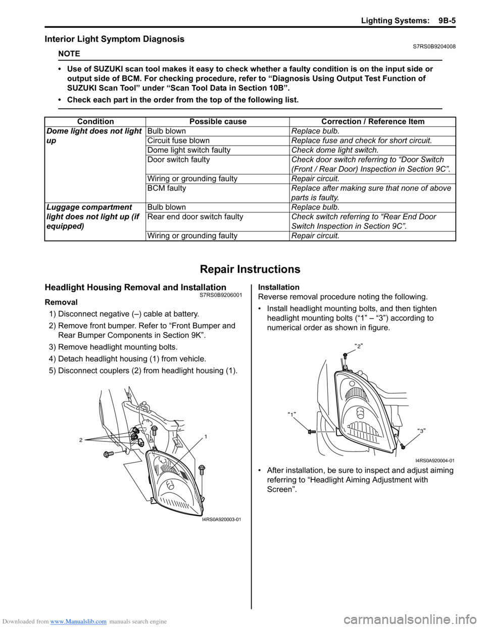
Headlight Housing Removal and InstallationS7RS0B9206001
Removal 1) Disconnect negative (–) cable at battery.
2) Remove front bumper. Refer to “Front Bumper and Rear Bumper Componen ts in Section 9K”.
3) Remove headlight mounting bolts.
4) Detach headlight housing (1) from vehicle.
5) Disconnect couplers (2) from headlight housing (1). Installation
Reverse removal procedure noting the following.
• Install headlight mounting bolts, and then tighten
headlight mounting bolts (“1” – “3”) according to
numerical order as shown in figure.
• After installation, be sure to inspect and adjust aiming referring to “Headlight Aiming Adjustment with
Screen”.
Condition Possible cause Correction / Reference Item
Dome light does not light
up Bulb blown
Replace bulb.
Circuit fuse blown Replace fuse and check for short circuit.
Dome light switch faulty Check dome light switch.
Door switch faulty Check door switch referring to “Door Switch
(Front / Rear Door) Inspection in Section 9C”.
Wiring or grounding faulty Repair circuit.
BCM faulty Replace after making sure that none of above
parts is faulty.
Luggage compartment
light does not light up (if
equipped) Bulb blown
Replace bulb.
Rear end door switch faulty Check switch referring to “Rear End Door
Switch Inspection in Section 9C”.
Wiring or grounding faulty Repair circuit.
2 1
I4RS0A920003-01
2
1 3
I4RS0A920004-01
Page 1291 of 1496
Downloaded from www.Manualslib.com manuals search engine Lighting Systems: 9B-9
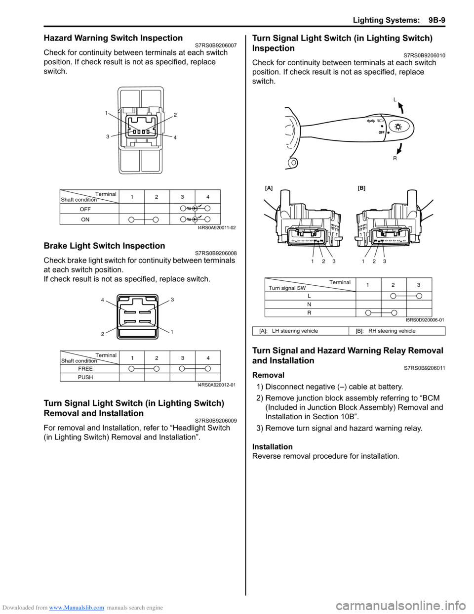
Hazard Warning Switch InspectionS7RS0B9206007
Check for continuity between terminals at each switch
position. If check result is not as specified, replace
switch.
Brake Light Switch InspectionS7RS0B9206008
Check brake light switch for continuity between terminals
at each switch position.
If check result is not as specified, replace switch.
Turn Signal Light Switch (in Lighting Switch)
Removal and Installation
S7RS0B9206009
For removal and Installation, refer to “Headlight Switch
(in Lighting Switch) Removal and Installation”.
Turn Signal Light Switch (in Lighting Switch)
Inspection
S7RS0B9206010
Check for continuity between terminals at each switch
position. If check result is not as specified, replace
switch.
Turn Signal and Hazard Warning Relay Removal
and Installation
S7RS0B9206011
Removal
1) Disconnect negative (–) cable at battery.
2) Remove junction block assembly referring to “BCM (Included in Junction Bl ock Assembly) Removal and
Installation in Section 10B”.
3) Remove turn signal and hazard warning relay.
Installation
Reverse removal procedure for installation.
Terminal
Shaft condition
OFF
ON 12 3 4
1
2
3 4
I4RS0A920011-02
4
2 3
1
Terminal
Shaft condition
FREE
PUSH 12 3 4
I4RS0A920012-01
[A]: LH steering vehicle
[B]: RH steering vehicle
L
R
Terminal
Turn signal SW 3
12
L
N
R 123
123
[A][B]
I5RS0D920006-01
Page 1305 of 1496
Downloaded from www.Manualslib.com manuals search engine Instrumentation / Driver Info. / Horn: 9C-10
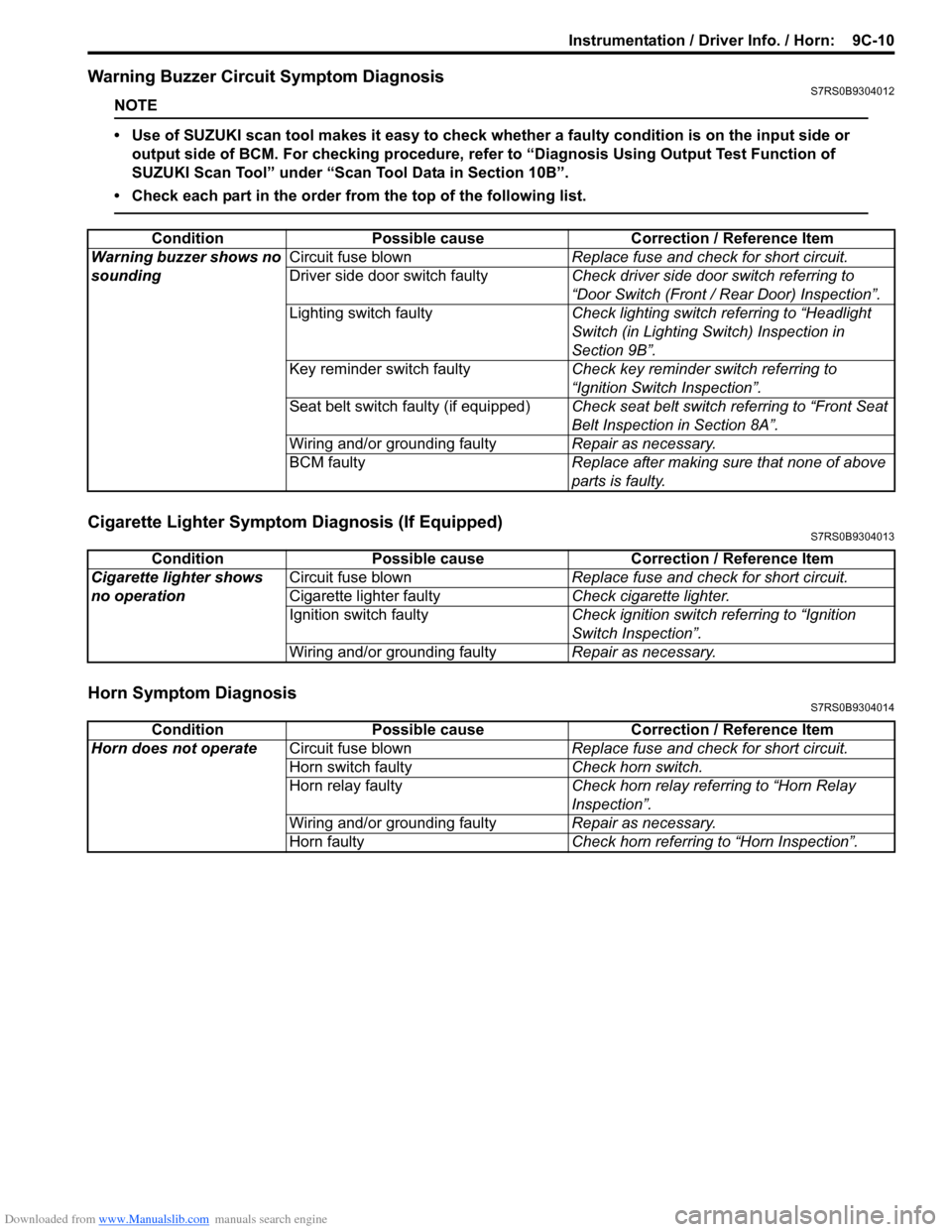
Warning Buzzer Circuit Symptom DiagnosisS7RS0B9304012
NOTE
• Use of SUZUKI scan tool makes it easy to check wh ether a faulty condition is on the input side or
output side of BCM. For checking procedure, re fer to “Diagnosis Using Output Test Function of
SUZUKI Scan Tool” under “Scan Tool Data in Section 10B”.
• Check each part in the order from the top of the following list.
Cigarette Lighter Symptom Diagnosis (If Equipped)S7RS0B9304013
Horn Symptom DiagnosisS7RS0B9304014
Condition Possible cause Correction / Reference Item
Warning buzzer shows no
sounding Circuit fuse blown
Replace fuse and check for short circuit.
Driver side door switch faulty Check driver side door switch referring to
“Door Switch (Front / Rear Door) Inspection”.
Lighting switch faulty Check lighting switch referring to “Headlight
Switch (in Lighting Switch) Inspection in
Section 9B”.
Key reminder switch faulty Check key reminder switch referring to
“Ignition Switch Inspection”.
Seat belt switch faulty (if equipped) Check seat belt switch referring to “Front Seat
Belt Inspection in Section 8A”.
Wiring and/or grounding faulty Repair as necessary.
BCM faulty Replace after making sure that none of above
parts is faulty.
ConditionPossible cause Correction / Reference Item
Cigarette lighter shows
no operation Circuit fuse blown
Replace fuse and check for short circuit.
Cigarette lighter faulty Check cigarette lighter.
Ignition switch faulty Check ignition switch referring to “Ignition
Switch Inspection”.
Wiring and/or grounding faulty Repair as necessary.
ConditionPossible cause Correction / Reference Item
Horn does not operate Circuit fuse blown Replace fuse and check for short circuit.
Horn switch faulty Check horn switch.
Horn relay faulty Check horn relay referring to “Horn Relay
Inspection”.
Wiring and/or grounding faulty Repair as necessary.
Horn faulty Check horn referring to “Horn Inspection”.