Park light SUZUKI SWIFT 2008 2.G Service User Guide
[x] Cancel search | Manufacturer: SUZUKI, Model Year: 2008, Model line: SWIFT, Model: SUZUKI SWIFT 2008 2.GPages: 1496, PDF Size: 34.44 MB
Page 495 of 1496
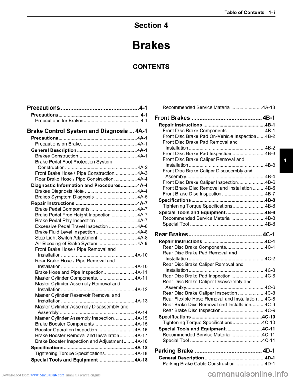
Downloaded from www.Manualslib.com manuals search engine Table of Contents 4- i
4
Section 4
CONTENTS
Brakes
Precautions ................................................. 4-1
Precautions............................................................. 4-1
Precautions for Brakes .......................................... 4-1
Brake Control System and Diagnosis ... 4A-1
Precautions........................................................... 4A-1Precautions on Brake .......................................... 4A-1
General Description ............................................. 4A-1 Brakes Construction ............................................ 4A-1
Brake Pedal Foot Protection System Construction ...................................................... 4A-2
Front Brake Hose / Pipe Co nstruction................. 4A-3
Rear Brake Hose / Pipe Construction ................. 4A-4
Diagnostic Information and Procedures ............ 4A-4 Brakes Diagnosis Note ....................................... 4A-4
Brakes Symptom Diagnosis ................................ 4A-5
Repair Instructions .............................................. 4A-7 Brake Pedal Components ................................... 4A-7
Brake Pedal Free Height Inspection ................... 4A-7
Brake Pedal Play Inspection ............................... 4A-7
Excessive Pedal Travel Inspection ..................... 4A-8
Brake Fluid Level Inspection ............................... 4A-8
Stop Light Switch Adjustment ............................. 4A-8
Air Bleeding of Brake System ............................. 4A-9
Front Brake Hose / Pipe Removal and Installation ....................................................... 4A-10
Rear Brake Hose / Pipe Removal and Installation ....................................................... 4A-10
Brake Hose and Pipe Inspection ....................... 4A-11
Master Cylinder Components............................ 4A-11
Master Cylinder Assembly Removal and Installation ....................................................... 4A-12
Master Cylinder Rese rvoir Removal and
Installation ....................................................... 4A-13
Master Cylinder Assemb ly Disassembly and
Assembly ........................................................ 4A-14
Master Cylinder Assembly Inspection ............... 4A-15
Brake Booster Components .............................. 4A-15
Booster Operation Inspection ........................... 4A-16
Brake Booster Removal and Installation ........... 4A-17
Brake Booster Inspection and Adjustment ........ 4A-18
Specifications ..................................................... 4A-18
Tightening Torque Specifications ...................... 4A-18
Special Tools and Equipmen t ........................... 4A-18 Recommended Service Material ....................... 4A-18
Front Brakes .......
..................................... 4B-1
Repair Instructions ........... ...................................4B-1
Front Disc Brake Components ............................ 4B-1
Front Disc Brake Pad On-Vehicle Inspection ...... 4B-2
Front Disc Brake Pad Removal and Installation ......................................................... 4B-2
Front Disc Brake Pad Inspection......................... 4B-3
Front Disc Brake Ca liper Removal and
Installation ......................................................... 4B-3
Front Disc Brake Caliper Disassembly and Assembly........................................................... 4B-4
Front Disc Brake Caliper In spection.................... 4B-6
Front Brake Disc Removal and Installation ......... 4B-6
Front Brake Disc Inspection ................................ 4B-7
Specifications .................... ...................................4B-8
Tightening Torque Specifications ........................ 4B-8
Special Tools and Equipmen t .............................4B-8
Recommended Service Material ......................... 4B-8
Special Tool ........................................................ 4B-8
Rear Brakes................... ........................... 4C-1
Repair Instructions ........... ...................................4C-1
Rear Disc Brake Components.............................4C-1
Rear Disc Brake Pad Removal and Installation .........................................................4C-2
Rear Disc Brake Caliper Removal and Installation .........................................................4C-3
Rear Disc Brake Pad Inspection .........................4C-6
Rear Disc Brake Caliper Disassembly and Assembly...........................................................4C-6
Rear Disc Brake Caliper Inspection ....................4C-8
Rear Flexible Hose Remova l and Installation .....4C-8
Rear Brake Disc Removal and Installation..........4C-9
Rear Brake Disc Inspection.................................4C-9
Specifications .................... .................................4C-10
Tightening Torque Specifications ......................4C-10
Special Tools and Equipmen t ...........................4C-11
Recommended Service Material .......................4C-11
Special Tool ......................................................4C-11
Parking Brake ................. ......................... 4D-1
General Description .............................................4D-1
Parking Brake Cable Construction ......................4D-1
Page 496 of 1496

Downloaded from www.Manualslib.com manuals search engine 4-ii Table of Contents
Repair Instructions ..............................................4D-2Parking Brake Inspection and Adjustment ..........4D-2
Parking Brake Cable Removal and Installation ......................................................... 4D-3
Parking Brake Lever Removal and Installation ....4D-3
Specifications .... ...................................................4D-4
Tightening Torque Specifications ........................4D-4
ABS ........................................... .................4E-1
Precautions........................................................... 4E-1
Precautions in Diagnosing Troubles ................... 4E-1
Precautions in On-Vehicle Service...................... 4E-1
Precautions in Hydraulic Unit Operation Check ................................................................ 4E-1
General Description ............................................. 4E-2 ABS Description .................................................. 4E-2
ABS Hydraulic Unit / Control Module Assembly Description ....................................... 4E-2
CAN Communication System Description........... 4E-3
Schematic and Routing Diagram ........................ 4E-4 ABS Schematic ................................................... 4E-4
ABS Wiring Circuit Diagram ................................ 4E-5
Component Location ........... ................................ 4E-7
ABS Components Location ................................. 4E-7
Front Wheel Speed Sensor Components Location ............................................................ 4E-7
Rear Wheel Speed Sensor Components Location ............................................................ 4E-8
Diagnostic Information and Procedures ............ 4E-8 ABS Check .......................................................... 4E-8
ABS Warning Light Check................................. 4E-10
EBD Warning Light (Brake Warning Light) Check .............................................................. 4E-10
DTC Check........................................................ 4E-11
DTC Table ......................................................... 4E-11
DTC Clearance ................................................. 4E-12
Scan Tool Data ................................................. 4E-12
ABS Warning Light Does Not Come ON at Ignition Switch ON .......................................... 4E-13
ABS Warning Light Comes ON Steady ............. 4E-14
EBD Warning Light (Brake Warning Light) Comes ON Steady .......................................... 4E-15
Serial Data Link Circuit Check .......................... 4E-16
DTC C1021, C1022 / C1025, C1026 / C1031, C1032 / C1035, C1036: Right-Front / Left-
Front / Right-Rear / Left-Rear Wheel Speed
Sensor Circuit or Sensor Ring ........................ 4E-18
DTC C1041 / C1045 / C1051 / C1055, DTC C1042 / C1046 / C1052 / C1056: Right-Front
/ Left-Front / Right-Rear / Left-Rear Inlet
Solenoid Circuit, Right-Front / Left-Front /
Right-Rear / Left-Rear Outlet Solenoid
Circuit .............................................................. 4E-20
DTC C1057: Power Source Circuit ................... 4E-21
DTC C1061: ABS Pump Motor and/or Motor Driver Circuit ................................................... 4E-22
DTC C1063: Solenoid Valve Power Supply Driver Circuit ................................................... 4E-23
DTC C1071: ABS Control Module..................... 4E-24 DTC U1073: Control Module Communication
Bus Off ............................................................ 4E-25
DTC U1100: Lost Communication with ECM (Reception Error)............................................. 4E-27
Repair Instructions ............ ................................ 4E-28
ABS Hydraulic Unit Operati on Check................ 4E-28
ABS Hydraulic Unit / Control Module
Assembly Components ...... ............................. 4E-29
ABS Hydraulic Unit / Control Module
Assembly On-Vehicle Inspection .................... 4E-29
ABS Hydraulic Unit / Control Module
Assembly Removal and Inst allation ................ 4E-29
Front / Rear Wheel Speed Sensor On-Vehicle Inspection ........................................................ 4E-31
Front Wheel Speed Sensor Removal and Installation ....................................................... 4E-32
Front Wheel Speed Sensor Inspection ............. 4E-32
Rear Wheel Speed Sensor Removal and Installation ....................................................... 4E-33
Rear Wheel Speed Sensor Inspection .............. 4E-34
Front Wheel Encoder On-Veh icle Inspection .... 4E-34
Front wheel Enco der Removal and
Installation ....................................................... 4E-34
Rear Wheel Encoder On-Veh icle Inspection..... 4E-34
Rear Wheel Encoder Removal and Installation ....................................................... 4E-34
Specifications ..................... ................................ 4E-35
Tightening Torque Specifications ...................... 4E-35
Special Tools and Equipmen t ........................... 4E-35
Special Tool ...................................................... 4E-35
Electronic Stability Prog ram ...................4F-1
Precautions ........................................................... 4F-1
Precautions in Diagnosing Troubles ................... 4F-1
Precautions in On-Vehicle Service...................... 4F-1
Precautions in Hydraulic Unit Operation Check ................................................................ 4F-1
Precautions in Sensor Calibration ....................... 4F-1
Precautions in Speedometer Test or Other Tests ................................................................. 4F-2
General Description ............................................. 4F-2 Electronic Stability Program Description ............. 4F-2
Electronic Stability Program Construction ........... 4F-3
ESP® Hydraulic Unit / Control Module
Assembly Description........................................ 4F-5
Warning Lamp, Indicator Lamp Description ........ 4F-6
CAN Communication System Description........... 4F-6
CAN Communication System For Electronic Stability Program Description ............................ 4F-7
Schematic and Routing Diagram ........................ 4F-8 Electronic Stability Program Schematic .............. 4F-8
Electronic Stability Program Wiring Circuit Diagram............................................................. 4F-9
Component Location ............ ............................. 4F-11
Electronic Stability Program Component
Location........................................................... 4F-11
Diagnostic Information and Procedures .......... 4F-12 Electronic Stability Program System Check ...... 4F-12
ESP® Warning lamp Check .............................. 4F-14
Page 503 of 1496
Downloaded from www.Manualslib.com manuals search engine Brake Control System and Diagnosis: 4A-5
If deterioration of rubber is evident, disassemble all
hydraulic parts and wash with alcohol. Dry these parts
with compressed air before assembly to keep alcohol out
of the system. Replace all rubber parts in the system,
including hoses. Also, when working on the brake
mechanisms, check for fluid on the linings.
If excessive fluid is found, replace the pads. If master cylinder piston seals
are satisfactory, check for
leakage or excessive heat co nditions. If leakage is not
found, drain fluid, flush with brake fluid, refill and bleed
system.
The system must be flushed if there is any doubt as to
the grade of fluid in the system or if fluid has been used
which contained parts that have been subjected to
contaminated fluid.
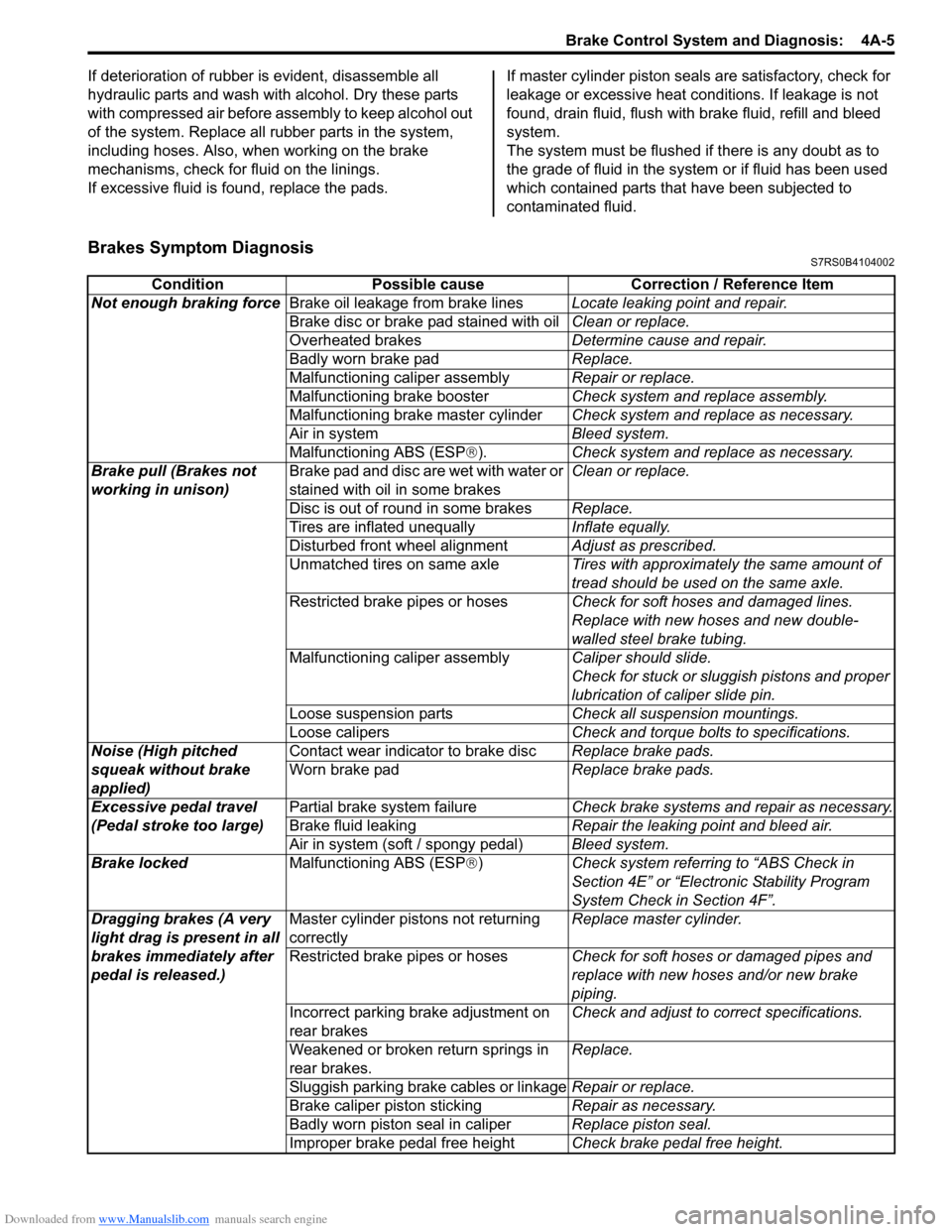
Brakes Symptom DiagnosisS7RS0B4104002
Condition Possible cause Correction / Reference Item
Not enough braking force Brake oil leakage from brake lines Locate leaking point and repair.
Brake disc or brake pad stained with oil Clean or replace.
Overheated brakes Determine cause and repair.
Badly worn brake pad Replace.
Malfunctioning caliper assembly Repair or replace.
Malfunctioning brake booster Check system and replace assembly.
Malfunctioning brake master cylinder Check system and replace as necessary.
Air in system Bleed system.
Malfunctioning ABS (ESP ®). Check system and replace as necessary.
Brake pull (Brakes not
working in unison) Brake pad and disc are wet with water or
stained with oil in some brakes Clean or replace.
Disc is out of round in some brakes Replace.
Tires are inflated unequally Inflate equally.
Disturbed front wheel alignment Adjust as prescribed.
Unmatched tires on same axle Tires with approximately the same amount of
tread should be used on the same axle.
Restricted brake pipes or hoses Check for soft hoses and damaged lines.
Replace with new hoses and new double-
walled steel brake tubing.
Malfunctioning caliper assembly Caliper should slide.
Check for stuck or sluggish pistons and proper
lubrication of caliper slide pin.
Loose suspension parts Check all suspension mountings.
Loose calipers Check and torque bolts to specifications.
Noise (High pitched
squeak without brake
applied) Contact wear indicator to brake disc
Replace brake pads.
Worn brake pad Replace brake pads.
Excessive pedal travel
(Pedal stroke too large) Partial brake system failure
Check brake systems and repair as necessary.
Brake fluid leaking Repair the leaking point and bleed air.
Air in system (soft / spongy pedal) Bleed system.
Brake locked Malfunctioning ABS (ESP®) Check system referri ng to “ABS Check in
Section 4E” or “Electronic Stability Program
System Check in Section 4F”.
Dragging brakes (A very
light drag is present in all
brakes immediately after
pedal is released.) Master cylinder pistons not returning
correctly
Replace master cylinder.
Restricted brake pipes or hoses Check for soft hoses or damaged pipes and
replace with new hoses and/or new brake
piping.
Incorrect parking brake adjustment on
rear brakes Check and adjust to correct specifications.
Weakened or broken return springs in
rear brakes. Replace.
Sluggish parking brake cables or linkage Repair or replace.
Brake caliper piston sticking Repair as necessary.
Badly worn piston seal in caliper Replace piston seal.
Improper brake pedal free height Check brake pedal free height.
Page 504 of 1496
Downloaded from www.Manualslib.com manuals search engine 4A-6 Brake Control System and Diagnosis:
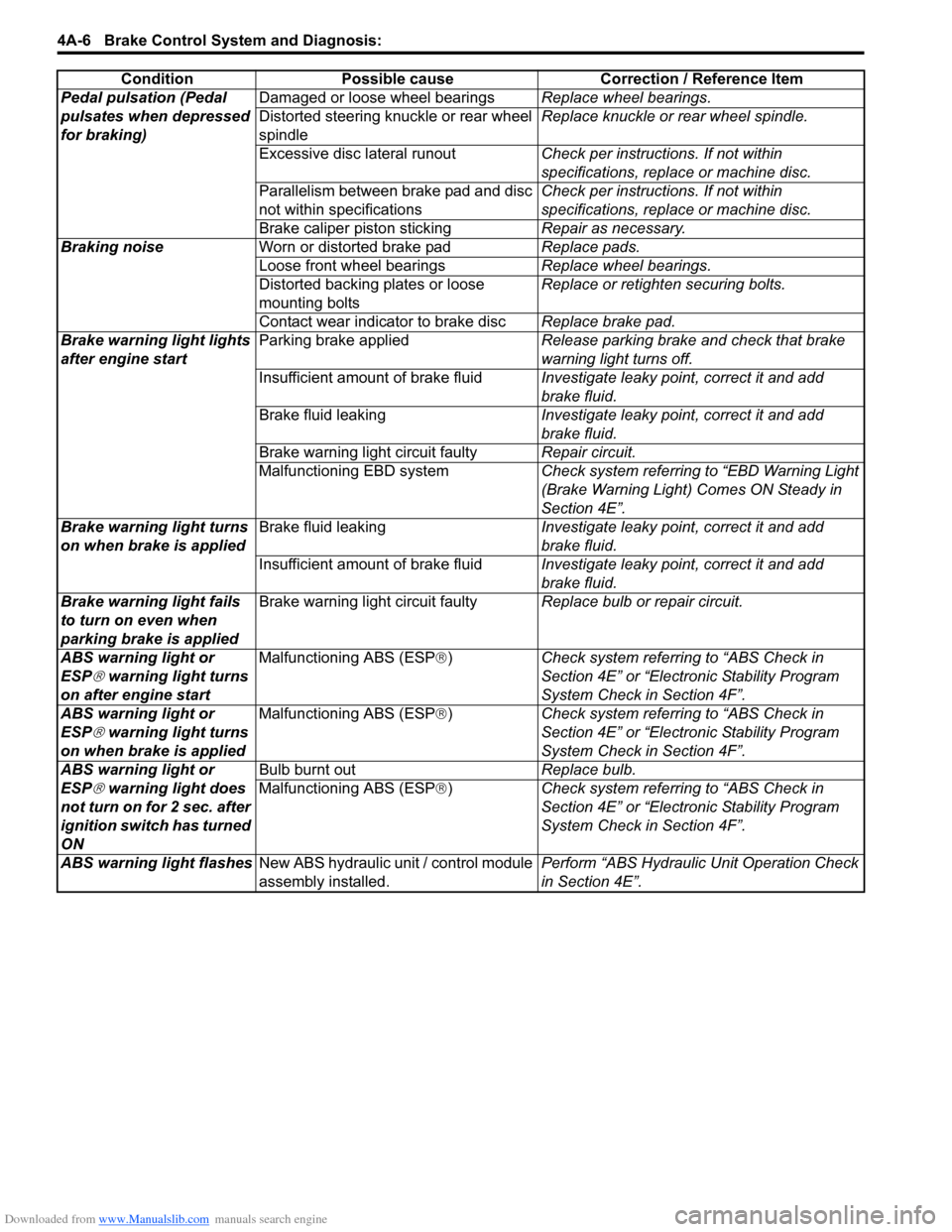
Pedal pulsation (Pedal
pulsates when depressed
for braking)Damaged or loose wheel bearings
Replace wheel bearings.
Distorted steering knuckle or rear wheel
spindle Replace knuckle or rear wheel spindle.
Excessive disc lateral runout Check per instructions. If not within
specifications, replace or machine disc.
Parallelism between brake pad and disc
not within specifications Check per instructions. If not within
specifications, replace or machine disc.
Brake caliper piston sticking Repair as necessary.
Braking noise Worn or distorted brake pad Replace pads.
Loose front wheel bearings Replace wheel bearings.
Distorted backing plates or loose
mounting bolts Replace or retighten securing bolts.
Contact wear indicator to brake disc Replace brake pad.
Brake warning light lights
after engine start Parking brake applied
Release parking brake and check that brake
warning light turns off.
Insufficient amount of brake fluid Investigate leaky point, correct it and add
brake fluid.
Brake fluid leaking Investigate leaky point, correct it and add
brake fluid.
Brake warning light circuit faulty Repair circuit.
Malfunctioning EBD system Check system referring to “EBD Warning Light
(Brake Warning Light) Comes ON Steady in
Section 4E”.
Brake warning light turns
on when brake is applied Brake fluid leaking
Investigate leaky point, correct it and add
brake fluid.
Insufficient amount of brake fluid Investigate leaky point, correct it and add
brake fluid.
Brake warning light fails
to turn on even when
parking brake is applied Brake warning light circuit faulty
Replace bulb or repair circuit.
ABS warning light or
ESP
® warning light turns
on after engine start Malfunctioning ABS (ESP
®) Check system referri ng to “ABS Check in
Section 4E” or “Electronic Stability Program
System Check in Section 4F”.
ABS warning light or
ESP
® warning light turns
on when brake is applied Malfunctioning ABS (ESP
®) Check system referri ng to “ABS Check in
Section 4E” or “Electronic Stability Program
System Check in Section 4F”.
ABS warning light or
ESP
® warning light does
not turn on for 2 sec. after
ignition switch has turned
ON Bulb burnt out
Replace bulb.
Malfunctioning ABS (ESP ®) Check system referri ng to “ABS Check in
Section 4E” or “Electronic Stability Program
System Check in Section 4F”.
ABS warning light flashes New ABS hydraulic unit / control module
assembly installed. Perform “ABS Hydraulic
Unit Operation Check
in Section 4E”.
Condition Possible cause Correction / Reference Item
Page 537 of 1496
Downloaded from www.Manualslib.com manuals search engine Parking Brake: 4D-2
Repair Instructions
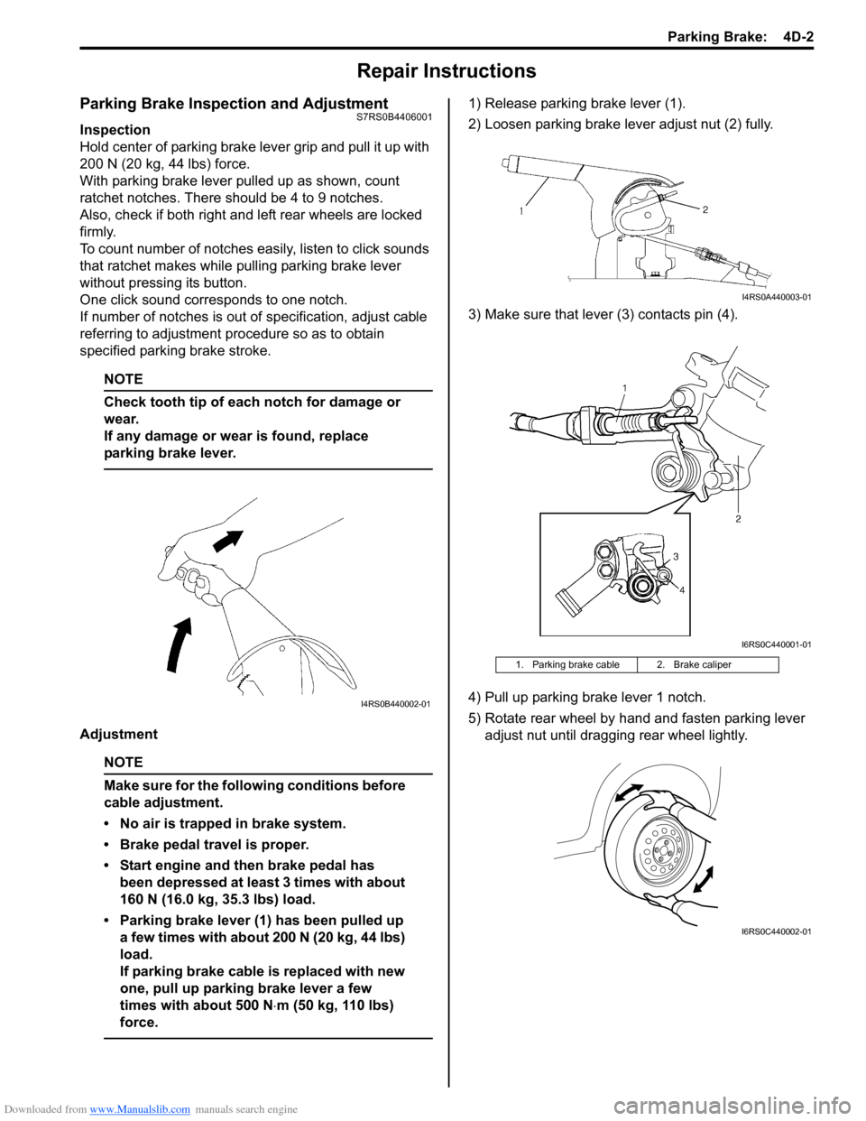
Parking Brake Inspection and AdjustmentS7RS0B4406001
Inspection
Hold center of parking brake lever grip and pull it up with
200 N (20 kg, 44 lbs) force.
With parking brake lever pulled up as shown, count
ratchet notches. There should be 4 to 9 notches.
Also, check if both right and left rear wheels are locked
firmly.
To count number of notches easily, listen to click sounds
that ratchet makes while pulling parking brake lever
without pressing its button.
One click sound corresponds to one notch.
If number of notches is out of specification, adjust cable
referring to adjustment procedure so as to obtain
specified parking brake stroke.
NOTE
Check tooth tip of each notch for damage or
wear.
If any damage or wear is found, replace
parking brake lever.
Adjustment
NOTE
Make sure for the following conditions before
cable adjustment.
• No air is trapped in brake system.
• Brake pedal travel is proper.
• Start engine and then brake pedal has been depressed at least 3 times with about
160 N (16.0 kg, 35.3 lbs) load.
• Parking brake lever (1) has been pulled up a few times with about 200 N (20 kg, 44 lbs)
load.
If parking brake cable is replaced with new
one, pull up parking brake lever a few
times with about 500 N ⋅m (50 kg, 110 lbs)
force.
1) Release parking brake lever (1).
2) Loosen parking brake lever adjust nut (2) fully.
3) Make sure that lever (3) contacts pin (4).
4) Pull up parking brake lever 1 notch.
5) Rotate rear wheel by hand and fasten parking lever adjust nut until dragging rear wheel lightly.
I4RS0B440002-01
1. Parking brake cable 2. Brake caliper
I4RS0A440003-01
I6RS0C440001-01
I6RS0C440002-01
Page 540 of 1496
Downloaded from www.Manualslib.com manuals search engine 4E-1 ABS:
Brakes
ABS
Precautions
Precautions in Diagnosing TroublesS7RS0B4500001
To ensure that the trouble diagnosis is done accurately
and smoothly, observe the following and follow “ABS
Check”.
• Diagnostic information stored in ABS cont rol module
memory can be cleared as well as checked by using
SUZUKI scan tool. Before us ing scan tool, read its
Operator’s (Instruction) Manual carefully to have good
understanding as to what functions are available and
how to use it.
• If the vehicles was operated in any of the following ways, ABS warning light may light momentarily but
this does not indicate anything abnormal in ABS.
– The vehicle was driven with parking brake pulled.
– The vehicle was driven with brake dragging.
– The vehicle was stuck in mud, sand, etc.
– Wheel spin occurred while driving.
– Wheel(s) was rotated while the vehicle was jacked up.
• Be sure to read “Precautions for Electrical Circuit Service in Section 00” befo re inspection and observe
what is written there.
• Be sure to use the trouble diagnosis procedure as described in “ABS Check”. Failure to follow it may
result in incorrect diagnosis. (Some other diagnosis
trouble code may be stored by mistake in the memory
of ABS control module during inspection.)
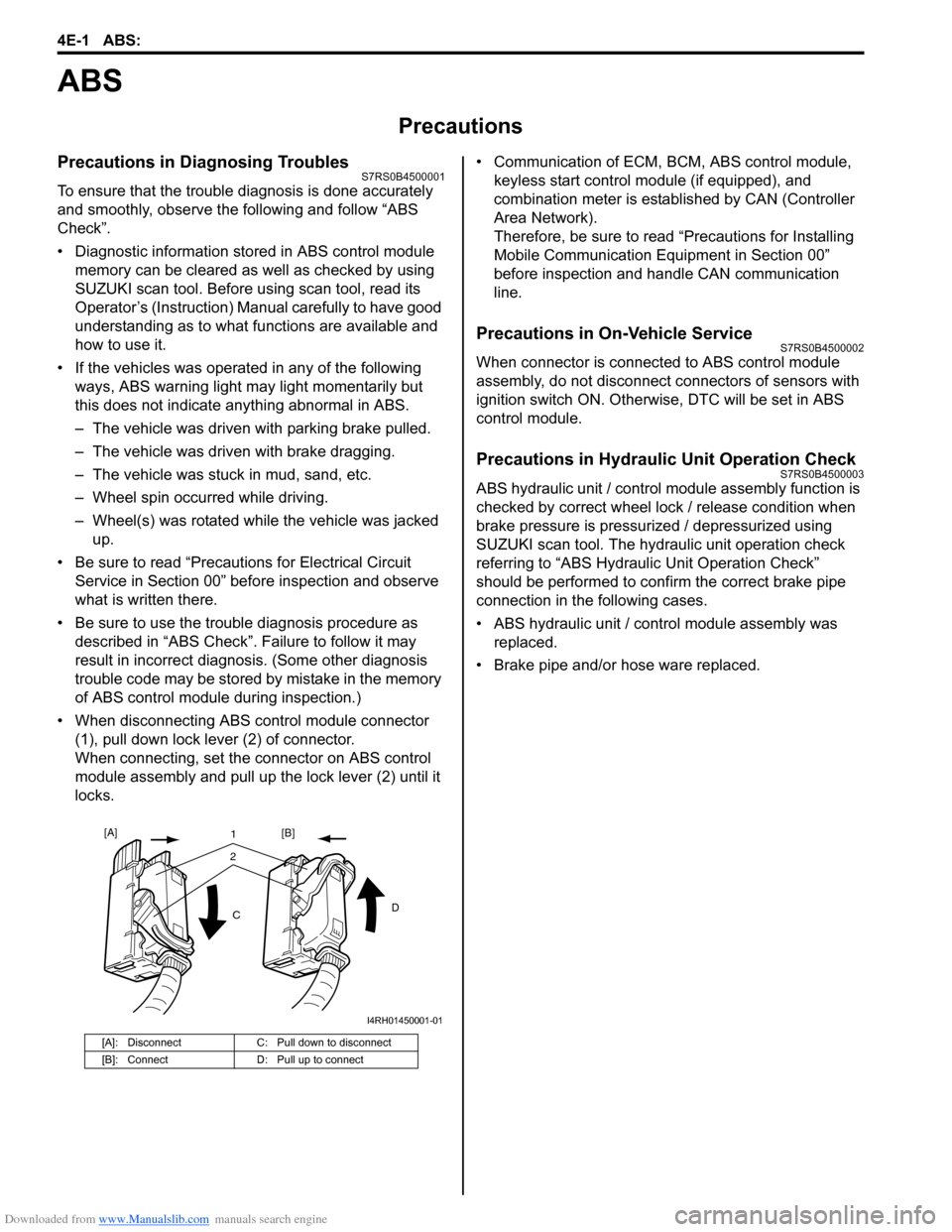
• When disconnecting ABS co ntrol module connector
(1), pull down lock lever (2) of connector.
When connecting, set the connector on ABS control
module assembly and pull up the lock lever (2) until it
locks. • Communication of ECM,
BCM, ABS control module,
keyless start control module (if equipped), and
combination meter is established by CAN (Controller
Area Network).
Therefore, be sure to read “Precautions for Installing
Mobile Communication Equipment in Section 00”
before inspection and handle CAN communication
line.
Precautions in On-Vehicle ServiceS7RS0B4500002
When connector is connected to ABS control module
assembly, do not disconnect connectors of sensors with
ignition switch ON. Otherwise, DTC will be set in ABS
control module.
Precautions in Hydraulic Unit Operation CheckS7RS0B4500003
ABS hydraulic unit / control module assembly function is
checked by correct wheel lock / release condition when
brake pressure is pressurized / depressurized using
SUZUKI scan tool. The hydraulic unit operation check
referring to “ABS Hydraulic Unit Operation Check”
should be performed to confirm the correct brake pipe
connection in the following cases.
• ABS hydraulic unit / cont rol module assembly was
replaced.
• Brake pipe and/or hose ware replaced.
[A]: Disconnect C: Pull down to disconnect
[B]: Connect D: Pull up to connect
21
C D
[A]
[B]
I4RH01450001-01
Page 545 of 1496
Downloaded from www.Manualslib.com manuals search engine ABS: 4E-6
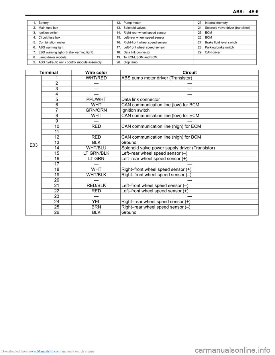
1. Battery12. Pump motor23. Internal memory
2. Main fuse box 13. Solenoid valves24. Solenoid valve driver (transistor)
3. Ignition switch 14. Right-rear wheel speed sensor25. ECM
4. Circuit fuse box 15. Left-rear wheel speed sensor26. BCM
5. Combination meter 16. Right-front wheel speed sensor27. Brake fluid level switch
6. ABS warning light 17. Left-front wheel speed sensor28. Parking brake switch
7. EBD warning light (Brake warning light) 18. Data link connector29. CAN driver
8. Lamp driver module 19. To ECM, SDM and BCM
9. ABS hydraulic unit / control module assembly 20. Stop lamp
Terminal Wire color Circuit
E03 1
WHT/RED ABS pump motor driver (Transistor)
2— —
3— —
4— —
5 PPL/WHT Data link connector
6 WHT CAN communication line (low) for BCM
7 GRN/ORN Ignition switch
8 WHT CAN communication line (low) for ECM
9— —
10 RED CAN communication line (high) for ECM
11 — —
12 RED CAN communication line (high) for BCM
13 BLK Ground
14 WHT/BLU Solenoid valve power supply driver (Transistor)
15 LT GRN/BLK Left–rear wheel speed sensor (–)
16 LT GRN Left–rear wheel speed sensor (+)
17 — —
18 WHT Right–front wheel speed sensor (+)
19 WHT/BLK Right–front wheel speed sensor (–)
20 — —
21 RED/BLK Left–front wheel speed sensor (–)
22 RED Left–front wheel speed sensor (+)
23 — —
24 YEL Right–rear wheel speed sensor (+)
25 BRN Right–rear wheel speed sensor (–)
26 BLK Ground
Page 549 of 1496
Downloaded from www.Manualslib.com manuals search engine ABS: 4E-10
Problem symptom confirmation
Check if what the customer claimed in “Customer
Questionnaire” is actually found in the vehicle and if that
symptom is found, whether it is identified as a failure.
(This step should be shared with the customer if
possible.) Check warning lights related to brake system
referring to “EBD Warning Light (Brake Warning Light)
Check” and “ABS Warning Light Check”.
DTC check, record and clearance
Perform “DTC Check” proced ure, record it and then
clear it referring to “DTC Clearance”.
Recheck DTC referring to “DTC Check”.
When DTC which is recorded at DTC check procedure is
detected again after performi ng DTC clearance, go to
“Step 4: ABS Check: ” to proceed the diagnosis.
When DTC which is recorded at DTC check procedure is
not indicated anymore after performing DTC clearance,
ABS control module does not perform the system
diagnosis, or temporary abnormality may occur,
therefore go to “Step 2: Driving Test: ” to proceed the
diagnosis.
Step 2: Driving Test
Test drive the vehicle at 40 km/h for more than a minute
and check if any trouble symptom (such as abnormal
lighting of ABS warn ing light) exists.
If the malfunction DTC is co nfirmed again at ignition
switch ON, driving test as described is not necessary.
Proceed to Step 3.
Step 3: DTC Check
Recheck DTC referring to “DTC Check”.
Step 4: ABS Check
According to ABS Check for the DTC confirmation in
Step 3, locate the cause of the trouble, namely in a
sensor, switch, wire harness, connector, actuator
assembly or other part and repair or replace faulty parts.
Step 5: Brakes Diagnosis
Check the parts or system suspected as a possible
cause referring to “Brakes Symptom Diagnosis in
Section 4A” and based on symptoms appearing on the
vehicle (symptom obtained through Steps 1 and 2 and
repair or replace faulty parts, if any).
Step 6: Check for Intermittent Problem
Check parts where an intermittent trouble is easy to
occur (e.g., wire harness, con nector, etc.), referring to
“Intermittent and Poor Connection Inspection in Section
00” and related circuit of trouble code recorded in Step 1
to 3.
Step 7: Final Confirmation Test
Confirm that the problem symptom has gone and the
ABS is free from any abnormal conditions. If what has
been repaired is related to the malfunction DTC, clear
the DTC once referring to “DTC Clearance” and perform
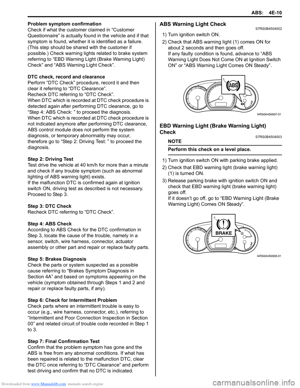
test driving and confirm that no DTC is indicated.ABS Warning Light CheckS7RS0B4504002
1) Turn ignition switch ON.
2) Check that ABS warning light (1) comes ON for
about 2 seconds and then goes off.
If any faulty condition is found, advance to “ABS
Warning Light Does Not Come ON at Ignition Switch
ON” or “ABS Warning Light Comes ON Steady”.
EBD Warning Light (Brake Warning Light)
Check
S7RS0B4504003
NOTE
Perform this check on a level place.
1) Turn ignition switch ON with parking brake applied.
2) Check that EBD warning lig ht (brake warning light)
(1) is turned ON.
3) Release parking brake with ignition switch ON and check that EBD warning lig ht (brake warning light)
goes off.
If it doesn’t go off, go to “EBD Warning Light (Brake
Warning Light) Comes ON Steady”.
11
I4RS0A450007-01
BRAKE
1
I4RS0A450008-01
Page 551 of 1496
Downloaded from www.Manualslib.com manuals search engine ABS: 4E-12
DTC ClearanceS7RS0B4504006
WARNING!
When performing a driving test, select a safe
place where there is neither any traffic nor
any traffic accident possibility and be very
careful during testing to avoid occurrence of
an accident.
After repair or replace malfunction part(s), clear all DTCs
by performing the following procedure or using SUZUKI
scan tool.
1) Connect SUZUKI scan tool to data link connector in the same manner as when making this connection
for DTC check.
2) Turn ignition switch to ON position.
3) Erase DTC according to instructions displayed on scan tool. Refer to scan tool operator’s manual for
further derails.
NOTE
For DTC C 1021, C1022, C1025, C1026, C1031,
C1032, C1035, C1036 and C1061, confirm that
ABS warning light turns off after performing
Step 2 of “Test Driving” under “ABS Check”,
and then clear the DTCs.
4) After completing the clear ance, turn ignition switch
OFF and disconnect scan tool from data link
connector.
5) Perform “Driving Test” (S tep 2 of “ABS Check”) and
“DTC Check” and confirm that NO DTC is displayed
on scan tool.
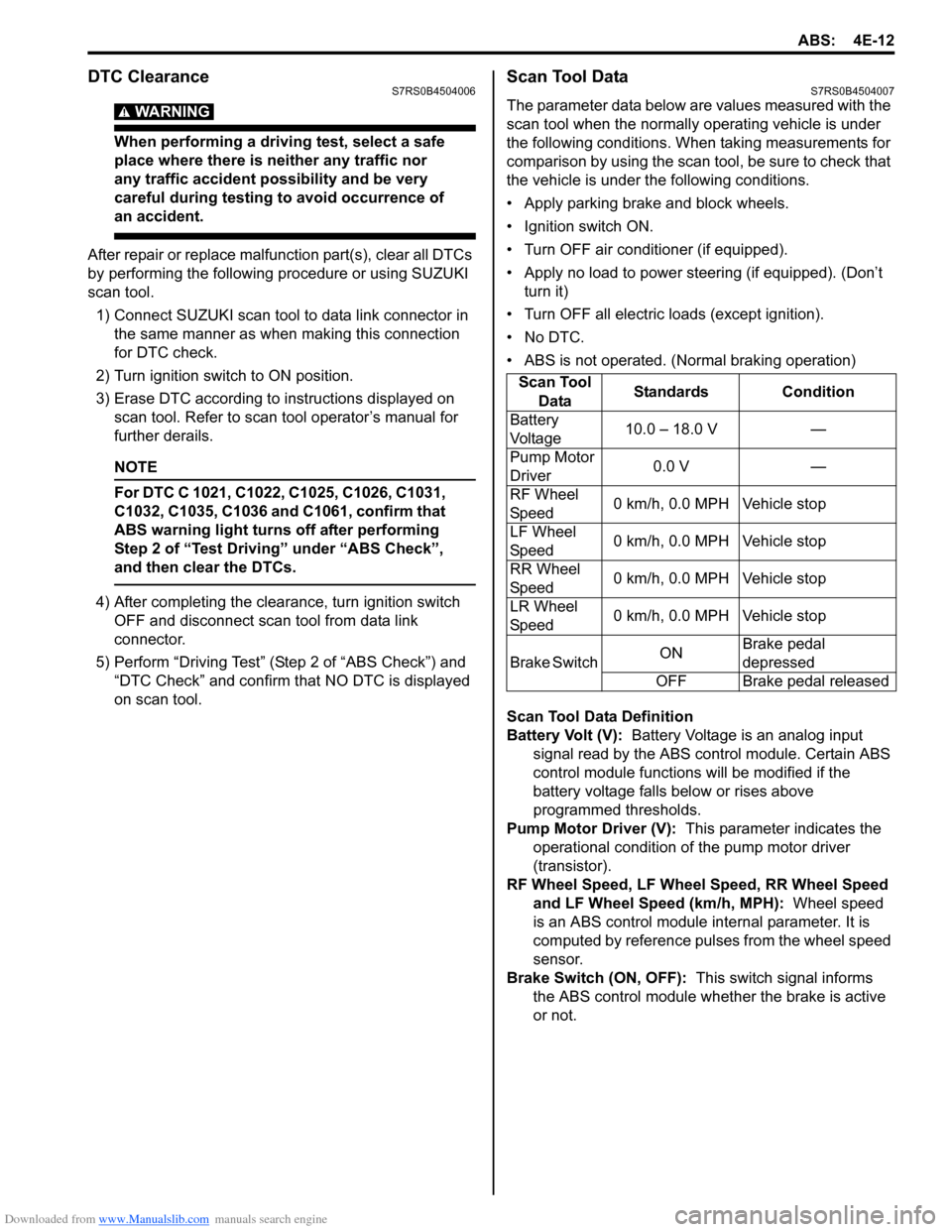
Scan Tool DataS7RS0B4504007
The parameter data below are values measured with the
scan tool when the normally operating vehicle is under
the following conditions. When taking measurements for
comparison by using the scan tool, be sure to check that
the vehicle is under the following conditions.
• Apply parking brake and block wheels.
• Ignition switch ON.
• Turn OFF air conditioner (if equipped).
• Apply no load to power steering (if equipped). (Don’t turn it)
• Turn OFF all electric loads (except ignition).
• No DTC.
• ABS is not operated. (N ormal braking operation)
Scan Tool Data Definition
Battery Volt (V): Battery Voltage is an analog input
signal read by the ABS control module. Certain ABS
control module function s will be modified if the
battery voltage falls below or rises above
programmed thresholds.
Pump Motor Driver (V): This parameter indicates the
operational condition of the pump motor driver
(transistor).
RF Wheel Speed, LF Wheel Speed, RR Wheel Speed and LF Wheel Speed (km/h, MPH): Wheel speed
is an ABS control module inte rnal parameter. It is
computed by reference pulses from the wheel speed
sensor.
Brake Switch (ON, OFF): This switch signal informs
the ABS control modu le whether the brake is active
or not.
Scan Tool
Data Standards Condition
Battery
Voltage 10.0 – 18.0 V —
Pump Motor
Driver 0.0 V —
RF Wheel
Sp ee d 0 km/h, 0.0 MPH Vehicle stop
LF Wheel
Sp ee d 0 km/h, 0.0 MPH Vehicle stop
RR Wheel
Sp ee d 0 km/h, 0.0 MPH Vehicle stop
LR Wheel
Sp ee d 0 km/h, 0.0 MPH Vehicle stop
Brake Switch ONBrake pedal
depressed
OFF Brake pedal released
Page 552 of 1496
Downloaded from www.Manualslib.com manuals search engine 4E-13 ABS:
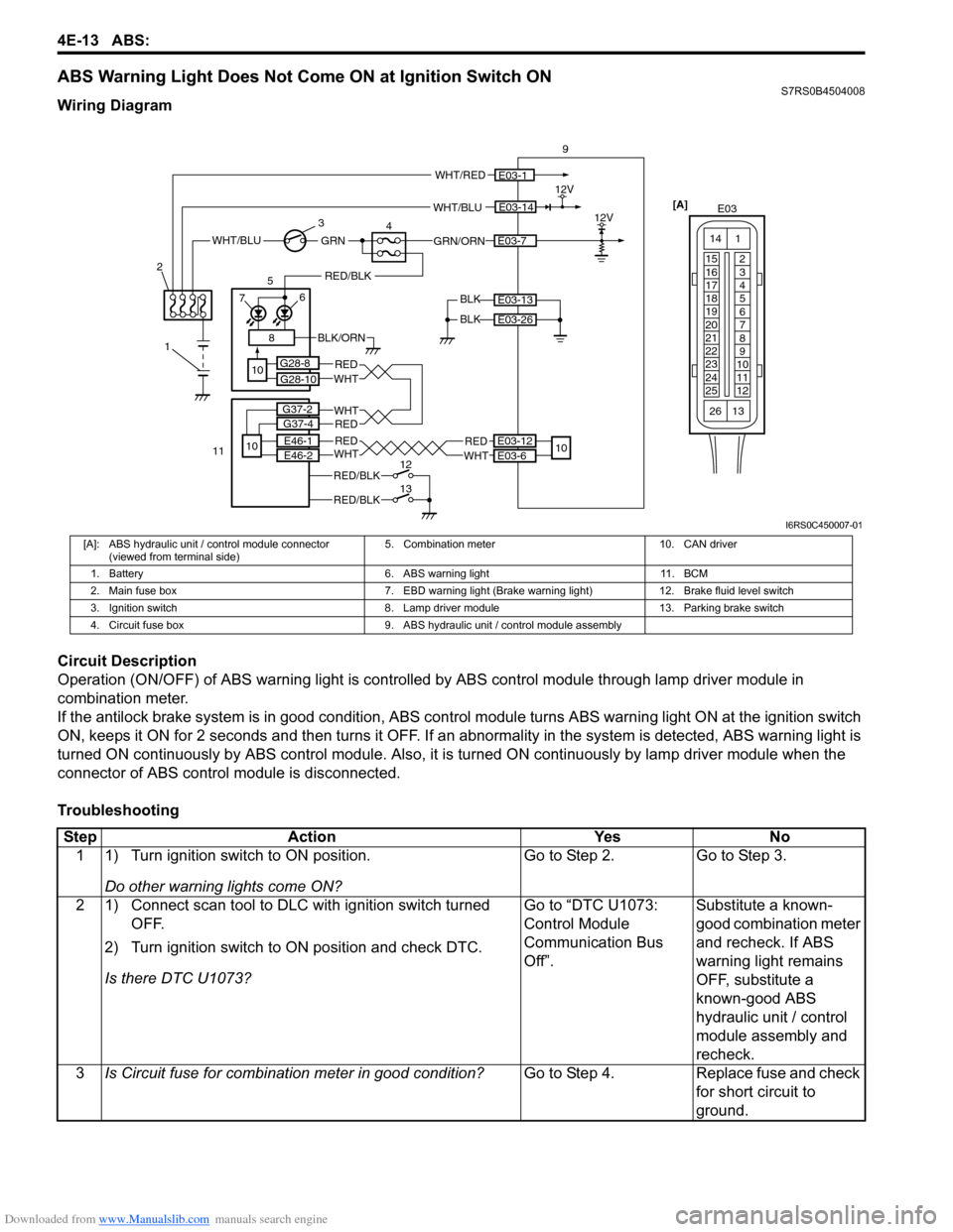
ABS Warning Light Does Not Come ON at Ignition Switch ONS7RS0B4504008
Wiring Diagram
Circuit Description
Operation (ON/OFF) of ABS warning light is controlled by ABS contro l module through lamp driver module in
combination meter.
If the antilock brake system is in good condition, ABS control module turns ABS warning light ON at the ignition switch
ON, keeps it ON for 2 seconds and then turns it OFF. If an abnormality in the system is detected, ABS warning light is
turned ON continuously by ABS control module. Also, it is turned ON continuously by la mp driver module when the
connector of ABS control module is disconnected.
Troubleshooting
WHT/BLU
BLK 12V
9
BLK
E03-14
E03-13
E03-26
WHT/RED
GRN/ORNE03-7WHT/BLUGRN
1
2
3
48
RED/BLK
76
5
10
E03-112V[A]
E03
15
16
17
18
19
20
21
22
23
24
25 2
3
4
5
6
7
8
9
10
11
12
1
13
14
26
BLK/ORN
E03-12
E03-6
REDWHT
10
G28-8
G28-10
REDWHTE46-1
E46-2
RED/BLK
RED/BLK
RED
RED
WHT
WHT
12
13
11
10
G37-2
G37-4
I6RS0C450007-01
[A]: ABS hydraulic unit / control module connector (viewed from terminal side) 5. Combination meter 10. CAN driver
1. Battery 6. ABS warning light 11. BCM
2. Main fuse box 7. EBD warning light (Brake warning light) 12. Brake fluid level switch
3. Ignition switch 8. Lamp driver module 13. Parking brake switch
4. Circuit fuse box 9. ABS hydraulic unit / control module assembly
Step Action YesNo
1 1) Turn ignition switch to ON position.
Do other warning lights come ON? Go to Step 2.
Go to Step 3.
2 1) Connect scan tool to DLC with ignition switch turned OFF.
2) Turn ignition switch to ON position and check DTC.
Is there DTC U1073? Go to “DTC U1073:
Control Module
Communication Bus
Off”.
Substitute a known-
good combination meter
and recheck. If ABS
warning light remains
OFF, substitute a
known-good ABS
hydraulic unit / control
module assembly and
recheck.
3 Is Circuit fuse fo r combination meter in good condition? Go to Step 4.Replace fuse and check
for short circuit to
ground.