Rail SUZUKI SWIFT 2008 2.G Service User Guide
[x] Cancel search | Manufacturer: SUZUKI, Model Year: 2008, Model line: SWIFT, Model: SUZUKI SWIFT 2008 2.GPages: 1496, PDF Size: 34.44 MB
Page 636 of 1496

Downloaded from www.Manualslib.com manuals search engine 4F-62 Electronic Stability Program:
4) Turn ignition switch to ON position and select menu “DATA LIST” mode of SUZUKI scan tool. Refer to
scan tool operator's manual for further derails.
5) When brake pedal is released, check “Master Cyl Press” under “DATA LIST” of SUZUKI scan tool.
If pressure is out of specification, replace ESP ®
hydraulic unit / cont rol module assembly.
Master cylinder pressure specification
Brake pedal released: 0 ± 0.8 MPa (0 ± 8 kg/cm2, 0
± 113 psi)
6) Hoist vehicle and remove right-side front wheel.
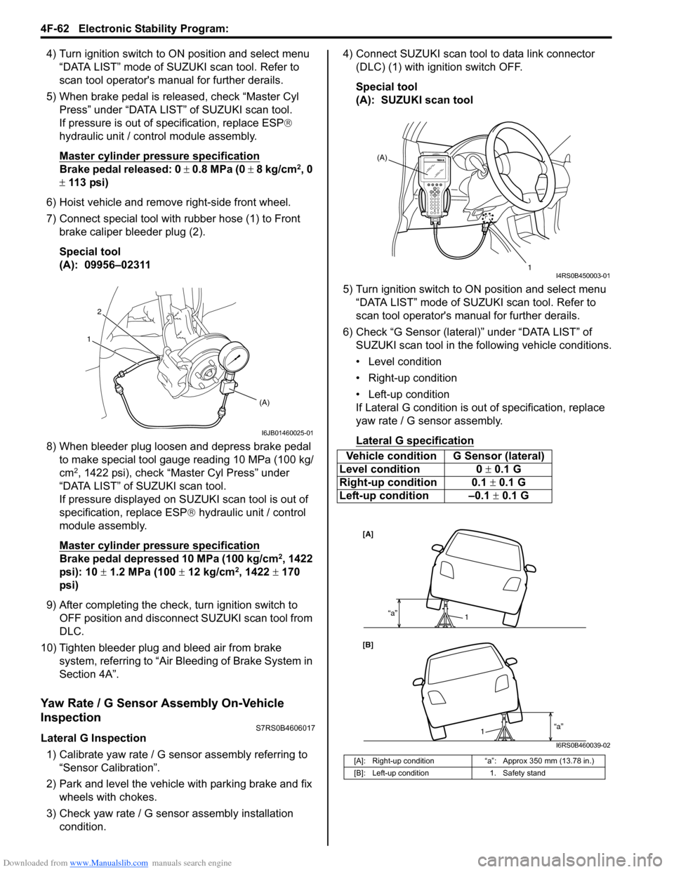
7) Connect special tool with rubber hose (1) to Front brake caliper bleeder plug (2).
Special tool
(A): 09956–02311
8) When bleeder plug loosen and depress brake pedal to make special tool gauge reading 10 MPa (100 kg/
cm
2, 1422 psi), check “Master Cyl Press” under
“DATA LIST” of SUZUKI scan tool.
If pressure displayed on SUZUKI scan tool is out of
specification, replace ESP ® hydraulic unit / control
module assembly.
Master cylinder pressure specification
Brake pedal depressed 10 MPa (100 kg/cm2, 1422
psi): 10 ± 1.2 MPa (100 ± 12 kg/cm2, 1422 ± 170
psi)
9) After completing the check, turn ignition switch to
OFF position and disconnect SUZUKI scan tool from
DLC.
10) Tighten bleeder plug and bleed air from brake system, referring to “Air Bleeding of Brake System in
Section 4A”.
Yaw Rate / G Sensor Assembly On-Vehicle
Inspection
S7RS0B4606017
Lateral G Inspection
1) Calibrate yaw rate / G sens or assembly referring to
“Sensor Calibration”.
2) Park and level the vehicle with parking brake and fix wheels with chokes.
3) Check yaw rate / G sensor assembly installation
condition. 4) Connect SUZUKI scan tool to data link connector
(DLC) (1) with ignition switch OFF.
Special tool
(A): SUZUKI scan tool
5) Turn ignition switch to ON position and select menu “DATA LIST” mode of SUZUKI scan tool. Refer to
scan tool operator's manual for further derails.
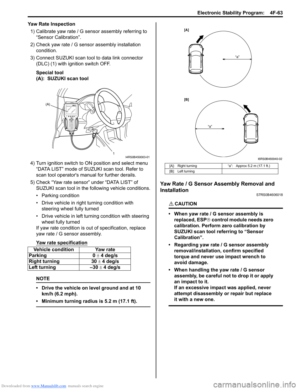
6) Check “G Sensor (lateral)” under “DATA LIST” of SUZUKI scan tool in the following vehicle conditions.
• Level condition
• Right-up condition
• Left-up condition
If Lateral G condition is ou t of specification, replace
yaw rate / G sensor assembly.
Lateral G sp ecification
2
(A)
1
I6JB01460025-01
Vehicle condition G Sensor (lateral)
Level condition 0 ± 0.1 G
Right-up condition 0.1 ± 0.1 G
Left-up condition –0.1 ± 0.1 G
[A]: Right-up condition “a”: Approx 350 mm (13.78 in.)
[B]: Left-up condition 1. Safety stand
(A)
1
I4RS0B450003-01
[A]
[B]“a”
1
“a”1
I6RS0B460039-02
Page 637 of 1496

Downloaded from www.Manualslib.com manuals search engine Electronic Stability Program: 4F-63
Yaw Rate Inspection1) Calibrate yaw rate / G sens or assembly referring to
“Sensor Calibration”.
2) Check yaw rate / G sensor assembly installation
condition.
3) Connect SUZUKI scan tool to data link connector (DLC) (1) with ignition switch OFF.
Special tool
(A): SUZUKI scan tool
4) Turn ignition switch to ON position and select menu
“DATA LIST” mode of SUZUKI scan tool. Refer to
scan tool operator's manual for further derails.
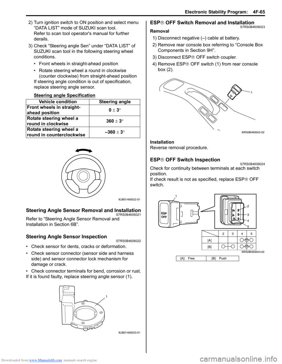
5) Check “Yaw rate sensor” under “DATA LIST” of SUZUKI scan tool in the following vehicle conditions.
• Parking condition
• Drive vehicle in right turning condition with steering wheel fully turned
• Drive vehicle in left tu rning condition with steering
wheel fully turned
If yaw rate condition is ou t of specification, replace
yaw rate / G sensor assembly.
Yaw rate specification
NOTE
• Drive the vehicle on level ground and at 10 km/h (6.2 mph).
• Minimum turning radius is 5.2 m (17.1 ft).
Yaw Rate / G Sensor Assembly Removal and
Installation
S7RS0B4606018
CAUTION!
• When yaw rate / G sensor assembly is replaced, ESP ® control module needs zero
calibration. Perform zero calibration by
SUZUKI scan tool referring to “Sensor
Calibration”.
• Regarding yaw rate / G sensor assembly removal/installation, confirm specified
torque and never use impact wrench to
avoid damage.
• When handling the yaw rate / G sensor assembly, be careful not to drop it or apply
an impact to it.
If an excessive impact was applied, never
attempt disassembly or repair but replace
it with a new one.
Vehicle condition Yaw rate
Parking 0 ± 4 deg/s
Right turning 30 ± 4 deg/s
Left turning –30 ± 4 deg/s
(A)
1
I4RS0B450003-01
[A]: Right turning“a”: Approx 5.2 m (17.1 ft.)
[B]: Left turning
[A]
[B] “a”
“a”
I6RS0B460040-02
Page 639 of 1496

Downloaded from www.Manualslib.com manuals search engine Electronic Stability Program: 4F-65
2) Turn ignition switch to ON position and select menu
“DATA LIST” mode of SUZUKI scan tool.
Refer to scan tool operator's manual for further
derails.
3) Check “Steering angle Sen” under “DATA LIST” of SUZUKI scan tool in th e following steering wheel
conditions.
• Front wheels in straight-ahead position
• Rotate steering wheel a round in clockwise (counter clockwise) from straight-ahead position
If steering angle condition is out of specification,
replace steering angle sensor.
Steering angle Specification
Steering Angle Sensor Removal and InstallationS7RS0B4606021
Refer to “Steering Angle Sensor Removal and
Installation in Section 6B”.
Steering Angle Sensor InspectionS7RS0B4606022
• Check sensor for dents, cracks or deformation.
• Check sensor connector (sensor side and harness
side) and sensor connector lock mechanism for
damage or crack.
• Check connector terminals for bend, corrosion or rust.
If it is found faulty, replace steering angle sensor (1).
ESP ® OFF Switch Removal and InstallationS7RS0B4606023
Removal
1) Disconnect negative (–) cable at battery.
2) Remove rear console box referring to “Console Box Components in Section 9H”.
3) Disconnect ESP ® OFF switch coupler.
4) Remove ESP ® OFF switch (1) from rear console
box (2).
Installation
Reverse removal procedure.
ESP ® OFF Switch InspectionS7RS0B4606024
Check for continuity between terminals at each switch
position.
If check result is not as specified, replace ESP ® OFF
switch.
Vehicle condition Steering angle
Front wheels in straight-
ahead position 0
± 3 °
Rotate steering wheel a
round in clockwise 360
± 3°
Rotate steering wheel a
round in counterclockwise –360
± 3 °
I6JB01460032-01
1
I6JB01460033-01
[A]: Free [B]: Push
1
I6RS0B460042-02
[A]
[B]2345
2
3
4
1
5
I6RS0B460043-02
Page 733 of 1496

Downloaded from www.Manualslib.com manuals search engine Automatic Transmission/Transaxle: 5A-89
A/T Fluid Level CheckS7RS0B5106002
CAUTION!
Do not use any fluid other than the specified
ATF. Use of any fluid other than the specified
ATF may cause juddering or some other
faulty condition to occur.
Level Check at Normal Operating (Hot) Temperature
– Hot Check1) Drive vehicle so that A/T fluid temperature reach the
normal operating temperature (70 – 80 °C (158 –
176 °F)).
2) Stop vehicle with engine running and place it level.
3) With select lever at “P” range, apply parking brake and place chocks against wheels.
4) Keep engine idling and shift selector slowly to “L” and back to “P” position.
5) With engine idling, pull out fluid level gauge, wipe it off with a clean cloth and put it back into place.
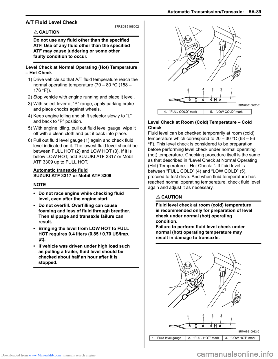
6) Pull out fluid level gauge (1) again and check fluid level indicated on it. The lo west fluid level should be
between FULL HOT (2) and LOW HOT (3). If it is
below LOW HOT, add SUZUKI ATF 3317 or Mobil
ATF 3309 up to FULL HOT.
Automatic transaxle fluid
SUZUKI ATF 3317 or Mobil ATF 3309
NOTE
• Do not race engine while checking fluid level, even after the engine start.
• Do not overfill. Overfilling can cause foaming and loss of fluid through breather.
Then slippage and transaxle failure can
result.
• Bringing the level from LOW HOT to FULL HOT requires 0.4 liters (0.85 / 0.70 US/Imp.
pt).
• If vehicle was driven under high load such as pulling a trailer, fluid level should be
checked about half an hour after it is
stopped.
Level Check at Room (Cold) Temperature – Cold
Check
Fluid level can be checked temporarily at room (cold)
temperature which correspond to 20 – 30 °C (68 – 86
° F). This level check is considered to be preparation
before performing level check under normal operating
(hot) temperature. Checking procedure itself is the same
as that described in “Level Check at Normal Operating
(Hot) Temperature – Hot Check: ”. If fluid level is
between “FULL COLD” (4) and “LOW COLD” (5),
proceed to test drive. And when fluid temperature has
reached normal operating temp erature, check fluid level
again and adjust it as necessary.
CAUTION!
Fluid level check at room (cold) temperature
is recommended only for preparation of level
check under normal (hot) operating
condition.
Failure to perform fluid level check under
normal (hot) operating temperature may
result in damage to transaxle.
4. “FULL COLD” mark 5. “LOW COLD” mark
1. Fluid level gauge 2. “FULL HOT” mark 3. “LOW HOT” mark
I3RM0B510032-01
I3RM0B510032-01