ignition timing SUZUKI SWIFT 2008 2.G Service User Guide
[x] Cancel search | Manufacturer: SUZUKI, Model Year: 2008, Model line: SWIFT, Model: SUZUKI SWIFT 2008 2.GPages: 1496, PDF Size: 34.44 MB
Page 103 of 1496
Downloaded from www.Manualslib.com manuals search engine Engine General Information and Diagnosis: 1A-53
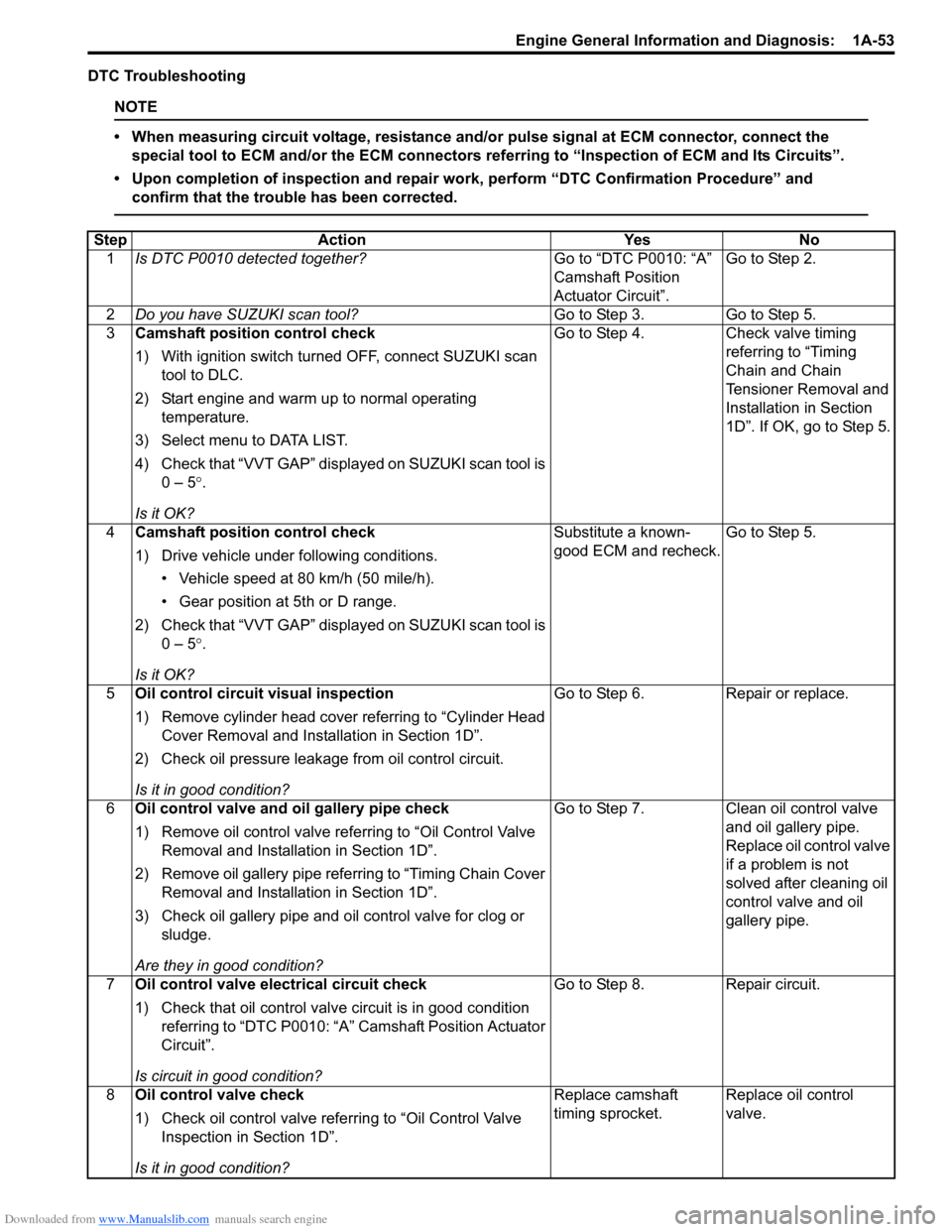
DTC Troubleshooting
NOTE
• When measuring circuit voltage, resistance and/or pulse signal at ECM connector, connect the
special tool to ECM and/or the ECM connectors re ferring to “Inspection of ECM and Its Circuits”.
• Upon completion of inspection and repair work, perform “DTC Confirmation Procedure” and confirm that the trouble has been corrected.
Step Action YesNo
1 Is DTC P0010 detected together? Go to “DTC P0010: “A”
Camshaft Position
Actuator Circuit”.Go to Step 2.
2 Do you have SUZUKI scan tool? Go to Step 3.Go to Step 5.
3 Camshaft position control check
1) With ignition switch turned OFF, connect SUZUKI scan
tool to DLC.
2) Start engine and warm up to normal operating temperature.
3) Select menu to DATA LIST.
4) Check that “VVT GAP” displayed on SUZUKI scan tool is 0 – 5 °.
Is it OK? Go to Step 4.
Check valve timing
referring to “Timing
Chain and Chain
Tensioner Removal and
Installation in Section
1D”. If OK, go to Step 5.
4 Camshaft position control check
1) Drive vehicle under following conditions.
• Vehicle speed at 80 km/h (50 mile/h).
• Gear position at 5th or D range.
2) Check that “VVT GAP” displayed on SUZUKI scan tool is 0 – 5 °.
Is it OK? Substitute a known-
good ECM and recheck.
Go to Step 5.
5 Oil control circuit visual inspection
1) Remove cylinder head cover referring to “Cylinder Head
Cover Removal and Insta llation in Section 1D”.
2) Check oil pressure leakage from oil control circuit.
Is it in good condition? Go to Step 6.
Repair or replace.
6 Oil control valve and oil gallery pipe check
1) Remove oil control valve re ferring to “Oil Control Valve
Removal and Installation in Section 1D”.
2) Remove oil gallery pipe refe rring to “Timing Chain Cover
Removal and Installation in Section 1D”.
3) Check oil gallery pipe and o il control valve for clog or
sludge.
Are they in good condition? Go to Step 7.
Clean oil control valve
and oil gallery pipe.
Replace oil control valve
if a problem is not
solved after cleaning oil
control valve and oil
gallery pipe.
7 Oil control valve electrical circuit check
1) Check that oil control valve circuit is in good condition
referring to “DTC P0010: “A” Camshaft Position Actuator
Circuit”.
Is circuit in good condition? Go to Step 8.
Repair circuit.
8 Oil control valve check
1) Check oil control valve refe rring to “Oil Control Valve
Inspection in Section 1D”.
Is it in good condition? Replace camshaft
timing sprocket.
Replace oil control
valve.
Page 155 of 1496
Downloaded from www.Manualslib.com manuals search engine Engine General Information and Diagnosis: 1A-105
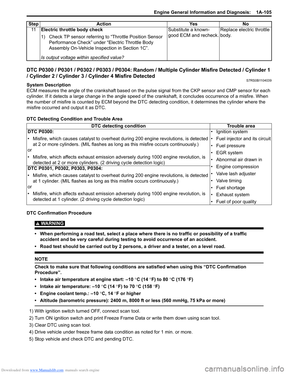
DTC P0300 / P0301 / P0302 / P0303 / P0304: Random / Multiple Cylinder Misfire Detected / Cylinder 1
/ Cylinder 2 / Cylinder 3 / Cylinder 4 Misfire Detected
S7RS0B1104039
System Description
ECM measures the angle of the crankshaft based on the pulse signal from the CKP sensor and CMP sensor for each
cylinder. If it detects a large change in the angle speed of the crankshaft, it concludes occurrence of a misfire. When
the number of misfire is counted by ECM beyond the DTC de tecting condition, it determines the cylinder where the
misfire occurred and output it as DTC.
DTC Detecting Condition and Trouble Area
DTC Confirmation Procedure
WARNING!
• When performing a road test, select a place where there is no traffic or possibility of a traffic accident and be very careful during testing to avoid occurrence of an accident.
• Road test should be carried out by 2 persons, a driver and a tester, on a level road.
NOTE
Check to make sure that following conditions ar e satisfied when using this “DTC Confirmation
Procedure”.
• Intake air temperature at engine start: –10 °C (14 ° F) to 80 °C (176 °F)
• Intake air temperature: –10 °C (14 °F) to 70 °C (158 °F)
• Engine coolant temp.: –10 °C, 14 °F or higher
• Altitude (barometric pressure): 2400 m, 8000 ft or less (560 mmHg, 75 kPa or more)
1) With ignition switch turned OFF, connect scan tool.
2) Turn ON ignition switch and print Freeze Frame Data or write them down using scan tool.
3) Clear DTC using scan tool.
4) Drive vehicle under freeze frame data condition as noted for 1 min. or more.
5) Stop vehicle and check DTC and pending DTC. 11
Electric throttle body check
1) Check TP sensor referring to “Throttle Position Sensor
Performance Check” under “Electric Throttle Body
Assembly On-Vehicle Inspection in Section 1C”.
Is output voltage within specified value? Substitute a known-
good ECM and recheck.
Replace electric throttle
body.
Step Action Yes No
DTC detecting condition
Trouble area
DTC P0300:
• Misfire, which causes catalyst to overheat during 200 engine revolutions, is detected at 2 or more cylinders. (MIL flashes as lo ng as this misfire occurs continuously.)
or
• Misfire, which affects exhaust emission adv ersely during 1000 engine revolution, is
detected at 2 or more cylinders. (2 driving cycle detection logic) • Ignition system
• Fuel injector and its circuit
• Fuel pressure
• EGR system
• Abnormal air drawn in
• Engine compression
• Valve lash adjuster
• Valve timing
• Fuel shortage
• Exhaust system
• Fuel of poor quality
DTC P0301, P0302, P0303, P0304:
• Misfire, which causes catalyst to overheat during 200 engine revolutions, is detected
at 1 cylinder. (MIL flashes as long as this misfire occurs continuously.)
or
• Misfire, which affects exhaust emission adv ersely during 1000 engine revolution, is
detected at 1 cylinder. (2 driving cycle detection logic)
Page 156 of 1496
Downloaded from www.Manualslib.com manuals search engine 1A-106 Engine General Information and Diagnosis:
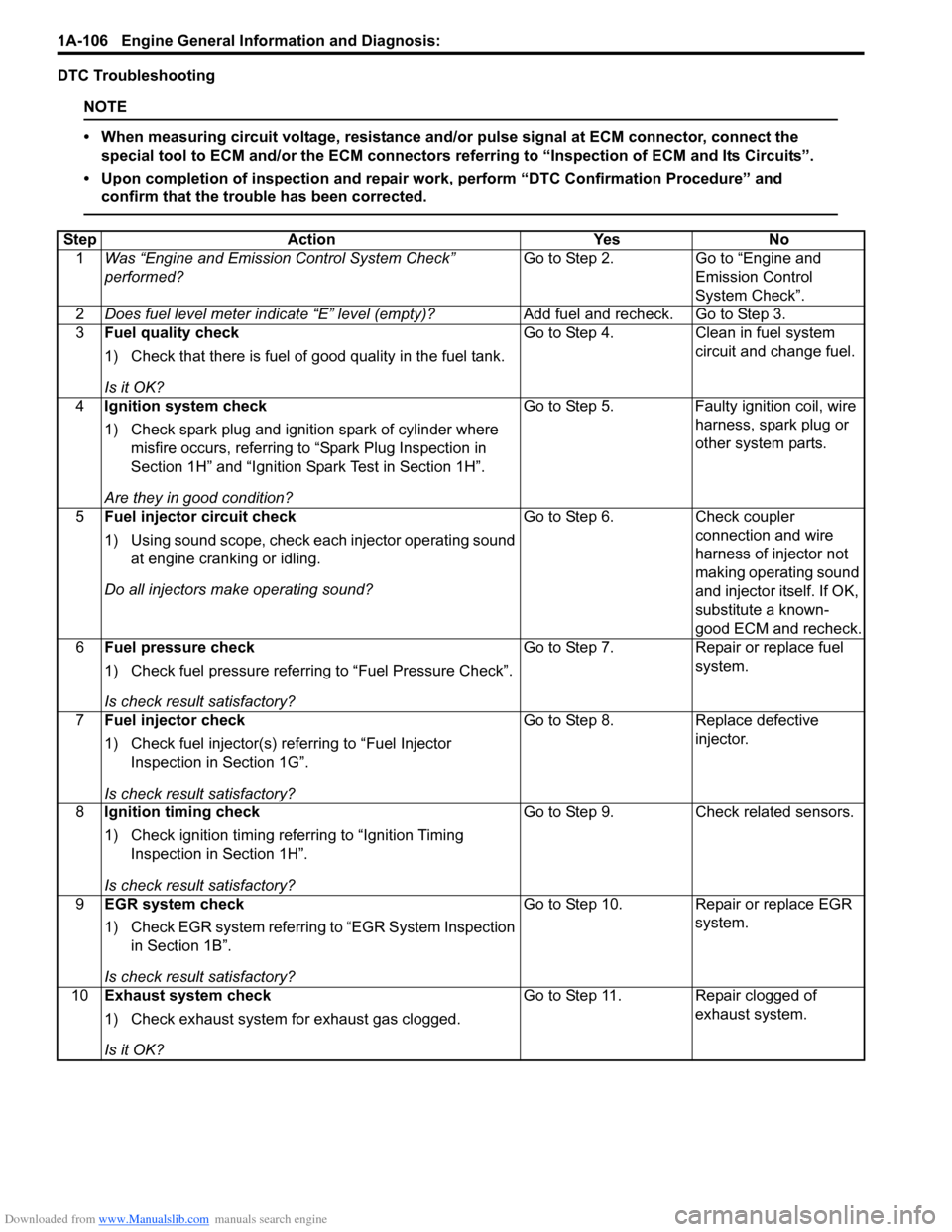
DTC Troubleshooting
NOTE
• When measuring circuit voltage, resistance and/or pulse signal at ECM connector, connect the
special tool to ECM and/or the ECM connectors re ferring to “Inspection of ECM and Its Circuits”.
• Upon completion of inspection and repair work, perform “DTC Confirmation Procedure” and confirm that the trouble has been corrected.
Step Action YesNo
1 Was “Engine and Emission Control System Check”
performed? Go to Step 2.
Go to “Engine and
Emission Control
System Check”.
2 Does fuel level meter in dicate “E” level (empty)? Add fuel and recheck. Go to Step 3.
3 Fuel quality check
1) Check that there is fuel of good quality in the fuel tank.
Is it OK? Go to Step 4.
Clean in fuel system
circuit and change fuel.
4 Ignition system check
1) Check spark plug and ignition spark of cylinder where
misfire occurs, referring to “Spark Plug Inspection in
Section 1H” and “Ignition Spark Test in Section 1H”.
Are they in good condition? Go to Step 5.
Faulty ignition coil, wire
harness, spark plug or
other system parts.
5 Fuel injector circuit check
1) Using sound scope, check each injector operating sound
at engine cranking or idling.
Do all injectors ma ke operating sound? Go to Step 6.
Check coupler
connection and wire
harness of injector not
making operating sound
and injector itself. If OK,
substitute a known-
good ECM and recheck.
6 Fuel pressure check
1) Check fuel pressure referring to “Fuel Pressure Check”.
Is check result satisfactory? Go to Step 7.
Repair or replace fuel
system.
7 Fuel injector check
1) Check fuel injector(s) re ferring to “Fuel Injector
Inspection in Section 1G”.
Is check result satisfactory? Go to Step 8.
Replace defective
injector.
8 Ignition timing check
1) Check ignition timing referring to “Ignition Timing
Inspection in Section 1H”.
Is check result satisfactory? Go to Step 9.
Check related sensors.
9 EGR system check
1) Check EGR system referring to “EGR System Inspection
in Section 1B”.
Is check result satisfactory? Go to Step 10. Repair or replace EGR
system.
10 Exhaust system check
1) Check exhaust system for exhaust gas clogged.
Is it OK? Go to Step 11. Repair clogged of
exhaust system.
Page 157 of 1496
Downloaded from www.Manualslib.com manuals search engine Engine General Information and Diagnosis: 1A-107
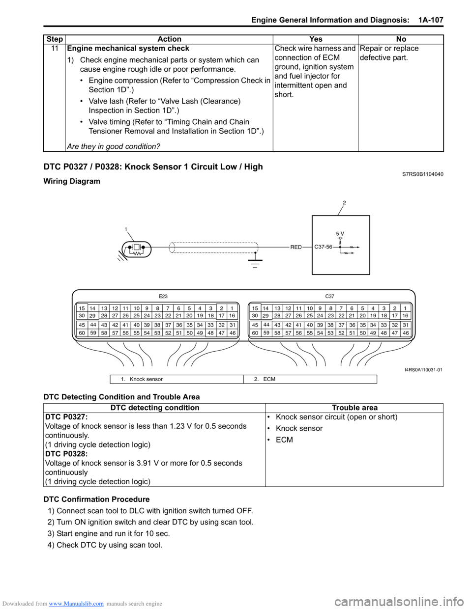
DTC P0327 / P0328: Knock Sensor 1 Circuit Low / HighS7RS0B1104040
Wiring Diagram
DTC Detecting Condition and Trouble Area
DTC Confirmation Procedure1) Connect scan tool to DLC with ignition switch turned OFF.
2) Turn ON ignition switch and clear DTC by using scan tool.
3) Start engine and run it for 10 sec.
4) Check DTC by using scan tool. 11
Engine mechanical system check
1) Check engine mechanical parts or system which can
cause engine rough idle or poor performance.
• Engine compression (Refer to “Compression Check in Section 1D”.)
• Valve lash (Refer to “Valve Lash (Clearance) Inspection in Section 1D”.)
• Valve timing (Refer to “Timing Chain and Chain Tensioner Removal and Installation in Section 1D”.)
Are they in good condition? Check wire harness and
connection of ECM
ground, ignition system
and fuel injector for
intermittent open and
short.
Repair or replace
defective part.
Step
Action YesNo
E23 C37
34
1819
567
1011
17
20
47 46
495051
2122
52 16
25 9
24
14
29
55
57 54 53
59
60 58 2
262728
15
30
56 4832 31
34353637
40
42 39 38
44
45 43 41 331
1213
238
34
1819
567
1011
17
20
47 46
495051
2122
52 16
25 9
24
14
29
55
57 54 53
59
60 58 2
262728
15
30
56 4832 31
34353637
40
42 39 38
44
45 43 41 331
1213
238
1 2
REDC37-56
5 V
I4RS0A110031-01
1. Knock sensor
2. ECM
DTC detecting condition Trouble area
DTC P0327:
Voltage of knock sensor is less than 1.23 V for 0.5 seconds
continuously.
(1 driving cycle detection logic)
DTC P0328:
Voltage of knock sensor is 3.91 V or more for 0.5 seconds
continuously
(1 driving cycle detection logic) • Knock sensor circuit (open or short)
• Knock sensor
•ECM
Page 266 of 1496
Downloaded from www.Manualslib.com manuals search engine 1A-216 Engine General Information and Diagnosis:
Repair Instructions
Idle Speed and IAC Throttle Valve Opening
Inspection
S7RS0B1106001
Before idle speed check, make sure of the following.
• Lead wires and hoses of electronic fuel injection and engine and emission control systems are connected
securely.
• Valve lash is checked according to maintenance schedule.
• Ignition timing is within specification.
• All accessories (wipers, heater, lights, A/C, etc.) are out of service.
• Air cleaner has been properly installed and is in good condition.
• No abnormal air drawn in from air intake system.
After all items are confirmed, check idle speed and IAC
duty as follows.
NOTE
Before starting engine, place transmission
gear shift lever in “Neutral” (shift selector
lever to “P” range for A/T vehicle), and set
parking brake and block drive wheels.
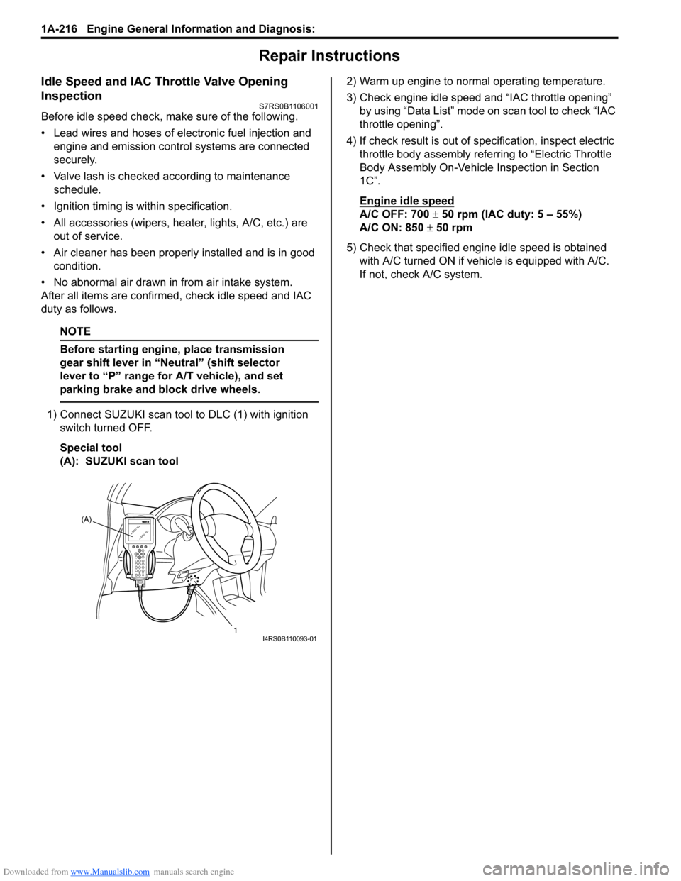
1) Connect SUZUKI scan tool to DLC (1) with ignition
switch turned OFF.
Special tool
(A): SUZUKI scan tool 2) Warm up engine to normal operating temperature.
3) Check engine idle speed and “IAC throttle opening”
by using “Data List” mode on scan tool to check “IAC
throttle opening”.
4) If check result is out of sp ecification, inspect electric
throttle body assembly referring to “Electric Throttle
Body Assembly On-Vehicle Inspection in Section
1C”.
Engine idle speed
A/C OFF: 700 ± 50 rpm (IAC duty: 5 – 55%)
A/C ON: 850 ± 50 rpm
5) Check that specified engine idle speed is obtained with A/C turned ON if vehi cle is equipped with A/C.
If not, check A/C system.
(A)
1
I4RS0B110093-01
Page 289 of 1496
Downloaded from www.Manualslib.com manuals search engine Engine Mechanical: 1D-4
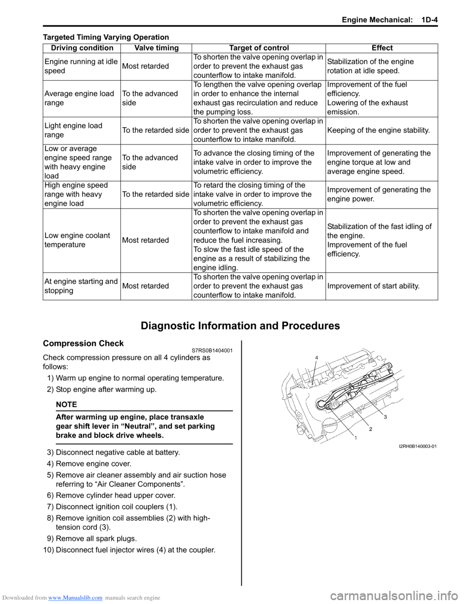
Targeted Timing Varying Operation
Diagnostic Information and Procedures
Compression CheckS7RS0B1404001
Check compression pressure on all 4 cylinders as
follows:
1) Warm up engine to normal operating temperature.
2) Stop engine after warming up.
NOTE
After warming up engine, place transaxle
gear shift lever in “Neutral”, and set parking
brake and block drive wheels.
3) Disconnect negative cable at battery.
4) Remove engine cover.
5) Remove air cleaner assembly and air suction hose referring to “Air Cleaner Components”.
6) Remove cylinder head upper cover.
7) Disconnect ignition coil couplers (1).
8) Remove ignition coil assemblies (2) with high- tension cord (3).
9) Remove all spark plugs.
10) Disconnect fuel injector wires (4) at the coupler. Driving condition Valve timing Target of control Effect
Engine running at idle
speed Most retardedTo shorten the valve opening overlap in
order to prevent the exhaust gas
counterflow to in
take manifold. Stabilization of the engine
rotation at idle speed.
Average engine load
range To the advanced
sideTo lengthen the valve opening overlap
in order to enhance the internal
exhaust gas recirculation and reduce
the pumping loss. Improvement of the fuel
efficiency.
Lowering of the exhaust
emission.
Light engine load
range To the retarded sideTo shorten the valve opening overlap in
order to prevent the exhaust gas
counterflow to in
take manifold. Keeping of the engine stability.
Low or average
engine speed range
with heavy engine
load To the advanced
side
To advance the closing timing of the
intake valve in order to improve the
volumetric efficiency. Improvement of generating the
engine torque at low and
average engine speed.
High engine speed
range with heavy
engine load To the retarded sideTo retard the closing timing of the
intake valve in order to improve the
volumetric efficiency. Improvement of generating the
engine power.
Low engine coolant
temperature Most retardedTo shorten the valve opening overlap in
order to prevent the exhaust gas
counterflow to intake manifold and
reduce the fuel increasing.
To slow the fast idle speed of the
engine as a result of stabilizing the
engine idling. Stabilization of the fast idling of
the engine.
Improvement of the fuel
efficiency.
At engine starting and
stopping Most retardedTo shorten the valve opening overlap in
order to prevent the exhaust gas
counterflow to in
take manifold. Improvement of start ability.I2RH0B140003-01
Page 296 of 1496
Downloaded from www.Manualslib.com manuals search engine 1D-11 Engine Mechanical:
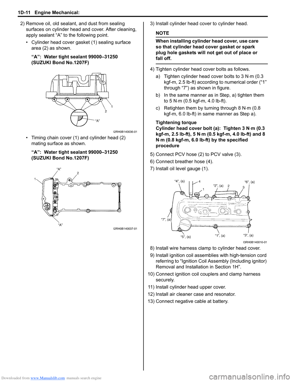
2) Remove oil, old sealant, and dust from sealing surfaces on cylinder head and cover. After cleaning,
apply sealant “A” to the following point.
• Cylinder head cover gasket (1) sealing surface area (2) as shown.
“A”: Water tight sealant 99000–31250
(SUZUKI Bond No.1207F)
• Timing chain cover (1) and cylinder head (2) mating surface as shown.
“A”: Water tight sealant 99000–31250
(SUZUKI Bond No.1207F) 3) Install cylinder head cover to cylinder head.
NOTE
When installing cylinder head cover, use care
so that cylinder head cover gasket or spark
plug hole gaskets will not get out of place or
fall off.
4) Tighten cylinder head cover bolts as follows.
a) Tighten cylinder head cover bolts to 3 N ⋅m (0.3
kgf-m, 2.5 lb-ft) according to numerical order (“1”
through “7”) as shown in figure.
b) In the same manner as in Step, a) tighten them
to 5 N ⋅m (0.5 kgf-m, 4.0 lb-ft).
c) Retighten them by turning through 8 N ⋅m (0.8
kgf-m, 6.0 lb-ft) in same manner as Step a).
Tightening torque
Cylinder head cover bolt (a): Tighten 3 N ⋅m (0.3
kgf-m, 2.5 lb-ft), 5 N ⋅m (0.5 kgf-m, 4.0 lb-ft) and 8
N ⋅m (0.8 kgf-m, 6.0 lb-ft) by the specified
procedure
5) Connect PCV hose (2) to PCV valve (3).
6) Connect breather hose (4).
7) Install oil level gauge (1).
8) Install wire harness clamp to cylinder head cover.
9) Install ignition coil assemb lies with high-tension cord
referring to “Ignit ion Coil Assembly (Including ignitor)
Removal and Installati on in Section 1H”.
10) Connect ignition coil couplers and clamp harness securely.
11) Install cylinder head upper cover.
12) Install air cleaner case and resonator.
13) Connect negative cable at battery.
I2RH0B140036-01
I2RH0B140037-01
I3RH0B140016-01
Page 367 of 1496
Downloaded from www.Manualslib.com manuals search engine Engine Cooling System: 1F-4
Diagnostic Information and Procedures
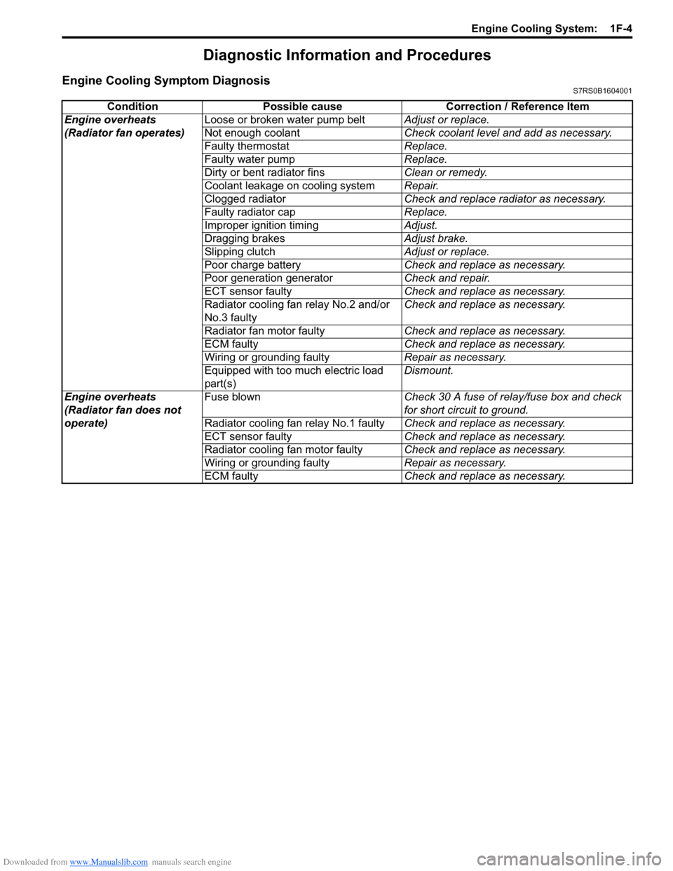
Engine Cooling Symptom DiagnosisS7RS0B1604001
ConditionPossible cause Correction / Reference Item
Engine overheats
(Radiator fan operates) Loose or broken water pump belt
Adjust or replace.
Not enough coolant Check coolant level and add as necessary.
Faulty thermostat Replace.
Faulty water pump Replace.
Dirty or bent radiator fins Clean or remedy.
Coolant leakage on cooling system Repair.
Clogged radiator Check and replace radiator as necessary.
Faulty radiator cap Replace.
Improper ignition timing Adjust.
Dragging brakes Adjust brake.
Slipping clutch Adjust or replace.
Poor charge battery Check and replace as necessary.
Poor generation generator Check and repair.
ECT sensor faulty Check and replace as necessary.
Radiator cooling fan relay No.2 and/or
No.3 faulty Check and replace as necessary.
Radiator fan motor faulty Check and replace as necessary.
ECM faulty Check and replace as necessary.
Wiring or grounding faulty Repair as necessary.
Equipped with too much electric load
part(s) Dismount.
Engine overheats
(Radiator fan does not
operate) Fuse blown
Check 30 A fuse of relay/fuse box and check
for short circuit to ground.
Radiator cooling fan relay No.1 faulty Check and replace as necessary.
ECT sensor faulty Check and replace as necessary.
Radiator cooling fan motor faulty Check and replace as necessary.
Wiring or grounding faulty Repair as necessary.
ECM faulty Check and replace as necessary.
Page 393 of 1496
Downloaded from www.Manualslib.com manuals search engine Ignition System: 1H-1
Engine
Ignition System
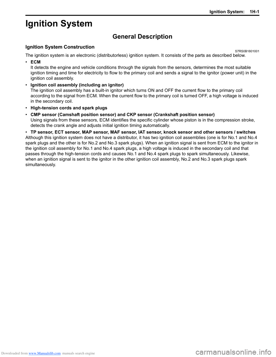
General Description
Ignition System ConstructionS7RS0B1801001
The ignition system is an electronic (distributorless) ignition system. It consists of the parts as described below.
• ECM
It detects the engine and vehicle conditions through the si gnals from the sensors, determines the most suitable
ignition timing and time for electricity to flow to the primar y coil and sends a signal to the ignitor (power unit) in the
ignition coil assembly.
• Ignition coil assembly (including an ignitor)
The ignition coil assembly has a built -in ignitor which turns ON and OFF the current flow to the primary coil
according to the signal from ECM. When the current flow to the primary coil is turned OFF, a high voltage is induced
in the secondary coil.
• High-tension cords and spark plugs
• CMP sensor (Camshaft position sensor) and CKP sensor (Crankshaft position sensor)
Using signals from these sensors, ECM identifies the specific cylinder whose piston is in the compression stroke,
detects the crank angle and adjusts in itial ignition timing automatically.
• TP sensor, ECT sensor, MAP sensor, MAF sensor, IAT sensor, knock sensor and other sensors / switches
Although this ignition system does not have a distributor, it has two ignition coil assemblies (one is for No.1 and No.4
spark plugs and the other is for No.2 and No.3 spark plugs). W hen an ignition signal is sent from ECM to the ignitor in
the ignition coil assembly for No.1 and No.4 spark plugs, a high voltage is induced in the secondary coil and that
passes through the high-tension cords and causes No.1 and No.4 spark plugs to spark simultaneously. Likewise,
when an ignition signal is sent to the ignitor in the ot her ignition coil assembly, No.2 and No.3 spark plugs spark
simultaneously.
Page 396 of 1496
Downloaded from www.Manualslib.com manuals search engine 1H-4 Ignition System:
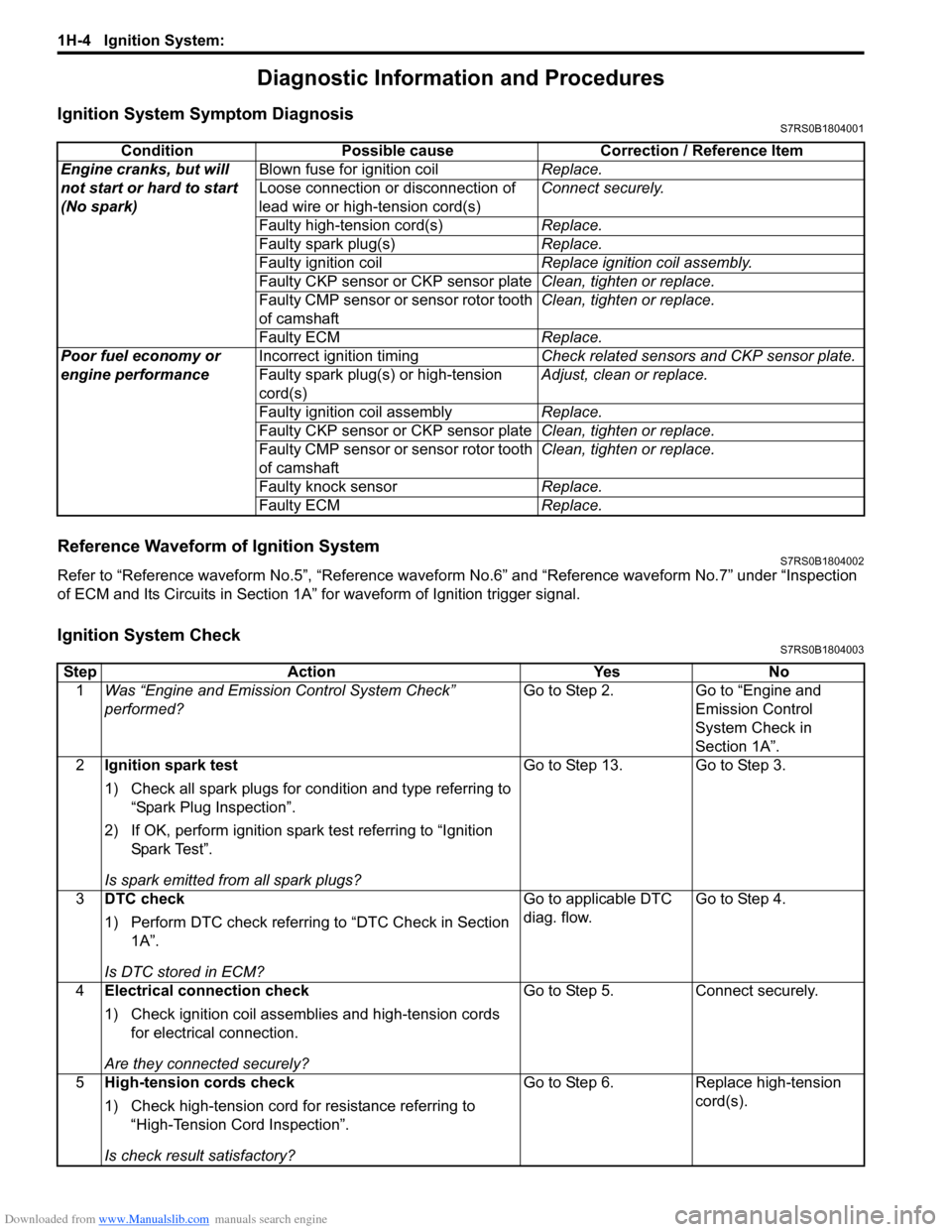
Diagnostic Information and Procedures
Ignition System Symptom DiagnosisS7RS0B1804001
Reference Waveform of Ignition SystemS7RS0B1804002
Refer to “Reference waveform No.5”, “Reference waveform No.6” and “Reference waveform No.7” under “Inspection
of ECM and Its Circuits in Section 1A” for waveform of Ignition trigger signal.
Ignition System CheckS7RS0B1804003
Condition Possible cause Correction / Reference Item
Engine cranks, but will
not start or hard to start
(No spark) Blown fuse for ignition coil
Replace.
Loose connection or disconnection of
lead wire or high-tension cord(s) Connect securely.
Faulty high-tension cord(s) Replace.
Faulty spark plug(s) Replace.
Faulty ignition coil Replace ignition coil assembly.
Faulty CKP sensor or CKP sensor plate Clean, tighten or replace.
Faulty CMP sensor or sensor rotor tooth
of camshaft Clean, tighten or replace.
Faulty ECM Replace.
Poor fuel economy or
engine performance Incorrect ignition timing
Check related sensors and CKP sensor plate.
Faulty spark plug(s) or high-tension
cord(s) Adjust, clean or replace.
Faulty ignition coil assembly Replace.
Faulty CKP sensor or CKP sensor plate Clean, tighten or replace.
Faulty CMP sensor or sensor rotor tooth
of camshaft Clean, tighten or replace.
Faulty knock sensor Replace.
Faulty ECM Replace.
StepAction YesNo
1 Was “Engine and Emission Control System Check”
performed? Go to Step 2.
Go to “Engine and
Emission Control
System Check in
Section 1A”.
2 Ignition spark test
1) Check all spark plugs for condition and type referring to
“Spark Plug Inspection”.
2) If OK, perform ignition spark test referring to “Ignition Spar k Tes t”.
Is spark emitted from all spark plugs? Go to Step 13. Go to Step 3.
3 DTC check
1) Perform DTC check referring to “DTC Check in Section
1A”.
Is DTC stored in ECM? Go to applicable DTC
diag. flow.
Go to Step 4.
4 Electrical connection check
1) Check ignition coil assemblies and high-tension cords
for electrical connection.
Are they connected securely? Go to Step 5.
Connect securely.
5 High-tension cords check
1) Check high-tension cord for resistance referring to
“High-Tension Cord Inspection”.
Is check result satisfactory? Go to Step 6.
Replace high-tension
cord(s).