reverse switch SUZUKI SWIFT 2008 2.G Service User Guide
[x] Cancel search | Manufacturer: SUZUKI, Model Year: 2008, Model line: SWIFT, Model: SUZUKI SWIFT 2008 2.GPages: 1496, PDF Size: 34.44 MB
Page 658 of 1496
Downloaded from www.Manualslib.com manuals search engine 5A-14 Automatic Transmission/Transaxle:
6. Output shaft speed sensor 13. Shift solenoid valve-A (No.1) 20. Transmission warning light
7. Input shaft speed sensor 14. Transmission range sensor
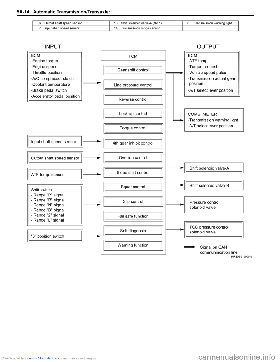
INPUT OUTPUT
TCMECM
Gear shift control
4th gear inhibit control
Slope shift control
Slip control
Lock up control
Torque control
Line pressure control
Overrun control
Reverse control
Squat control
Input shaft speed sensor
Output shaft speed sensor
"3" position switch ATF temp. sensor
Shift switch
- Range "P" signal
- Range "R" signal
- Range "N" signal
- Range "D" signal
- Range "2" signal
- Range "L" signal
Fail safe function
Self diagnosis
Warning function
ECM
Shift solenoid valve-A
Shift solenoid valve-B
TCC pressure control
solenoid valve
Pressure control
solenoid valve
Signal on CAN
communincation line
COMB. METER
-Engine torque
-Engine speed
-Throttle position
-A/C compressor clutch
-Coolant temperature
-Brake pedal switch -ATF temp.
-Torque request
-Vehicle speed pulse
-Transmission actual gear
position
-A/T select lever position
-Accelerator pedal position
-Transmission warning light
-A/T select lever position
I7RS0B510005-01
Page 673 of 1496
Downloaded from www.Manualslib.com manuals search engine Automatic Transmission/Transaxle: 5A-29
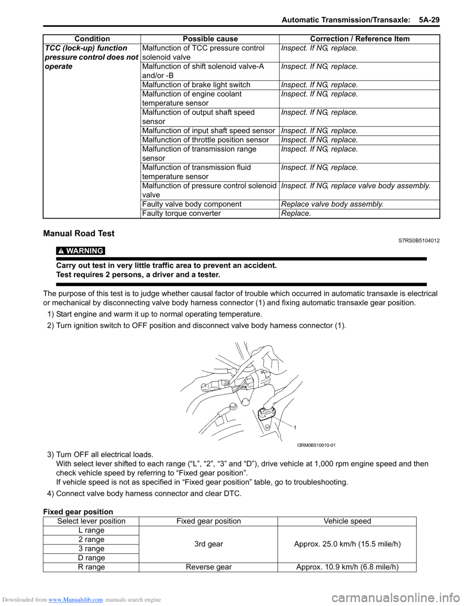
Manual Road TestS7RS0B5104012
WARNING!
Carry out test in very little traffic area to prevent an accident.
Test requires 2 persons, a driver and a tester.
The purpose of this test is to judge whether causal factor of trouble which occurred in automatic transaxle is electrical
or mechanical by disconnecting valve body harness co nnector (1) and fixing automatic transaxle gear position.
1) Start engine and warm it up to normal operating temperature.
2) Turn ignition switch to OFF position and disconnect valve body harness connector (1).
3) Turn OFF all electrical loads. With select lever shifted to each ra nge (“L”, “2”, “3” and “D”), drive vehi cle at 1,000 rpm engine speed and then
check vehicle speed by referring to “Fixed gear position”.
If vehicle speed is not as specified in “Fix ed gear position” table, go to troubleshooting.
4) Connect valve body harness connector and clear DTC.
Fixed gear position TCC (lock-up) function
pressure control does not
operate
Malfunction of TCC pressure control
solenoid valve
Inspect. If NG, replace.
Malfunction of shif t solenoid valve-A
and/or -B Inspect. If NG, replace.
Malfunction of brake light switch Inspect. If NG, replace.
Malfunction of engine coolant
temperature sensor Inspect. If NG, replace.
Malfunction of output shaft speed
sensor Inspect. If NG, replace.
Malfunction of input shaft speed sensor Inspect. If NG, replace.
Malfunction of throttle position sensor Inspect. If NG, replace.
Malfunction of transmission range
sensor Inspect. If NG, replace.
Malfunction of transmission fluid
temperature sensor Inspect. If NG, replace.
Malfunction of pressure control solenoid
valve Inspect. If NG, replace valve body assembly.
Faulty valve body component Replace valve body assembly.
Faulty torque converter Replace.
Condition
Possible cause Correction / Reference Item
Select lever positionFixed gear position Vehicle speed
L range
3rd gearApprox. 25.0 km/h (15.5 mile/h)
2 range
3 range
D range
R range Reverse gear Approx. 10.9 km/h (6.8 mile/h)
I3RM0B510010-01
Page 676 of 1496
Downloaded from www.Manualslib.com manuals search engine 5A-32 Automatic Transmission/Transaxle:
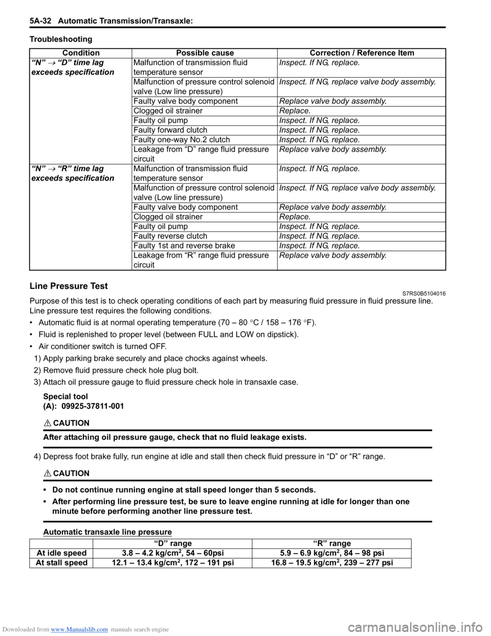
Troubleshooting
Line Pressure TestS7RS0B5104016
Purpose of this test is to check operat ing conditions of each part by measuring fluid pressure in fluid pressure line.
Line pressure test requires the following conditions.
• Automatic fluid is at normal operating temperature (70 – 80 °C / 158 – 176 °F).
• Fluid is replenished to proper level (between FULL and LOW on dipstick).
• Air conditioner switch is turned OFF.
1) Apply parking brake securely and place chocks against wheels.
2) Remove fluid pressure check hole plug bolt.
3) Attach oil pressure gauge to fluid pr essure check hole in transaxle case.
Special tool
(A): 09925-37811-001
CAUTION!
After attaching oil pressure gauge, check that no fluid leakage exists.
4) Depress foot brake fully, run engine at idle and stall then check fluid pressure in “D” or “R” range.
CAUTION!
• Do not continue running engine at stall speed longer than 5 seconds.
• After performing line pressure test, be sure to leave engine running at idle for longer than one minute before performing another line pressure test.
Automatic transaxle line pressure
Condition Possible cause Correction / Reference Item
“N”
→ “D” time lag
exceeds specification Malfunction of transmission fluid
temperature sensor Inspect. If NG, replace.
Malfunction of pressure control solenoid
valve (Low line pressure) Inspect. If NG, replace valve body assembly.
Faulty valve body component Replace valve body assembly.
Clogged oil strainer Replace.
Faulty oil pump Inspect. If NG, replace.
Faulty forward clutch Inspect. If NG, replace.
Faulty one-way No.2 clutch Inspect. If NG, replace.
Leakage from “D” range fluid pressure
circuit Replace valve body assembly.
“N”
→ “R” time lag
exceeds specification Malfunction of transmission fluid
temperature sensor Inspect. If NG, replace.
Malfunction of pressure control solenoid
valve (Low line pressure) Inspect. If NG, replace valve body assembly.
Faulty valve body component Replace valve body assembly.
Clogged oil strainer Replace.
Faulty oil pump Inspect. If NG, replace.
Faulty reverse clutch Inspect. If NG, replace.
Faulty 1st and reverse brake Inspect. If NG, replace.
Leakage from “R” range fluid pressure
circuit Replace valve body assembly.
“D” range
“R” range
At idle speed 3.8 – 4.2 kg/cm2, 54 – 60psi 5.9 – 6.9 kg/cm2, 84 – 98 psi
At stall speed 12.1 – 13.4 kg/cm2, 172 – 191 psi 16.8 – 19.5 kg/cm2, 239 – 277 psi
Page 684 of 1496
Downloaded from www.Manualslib.com manuals search engine 5A-40 Automatic Transmission/Transaxle:
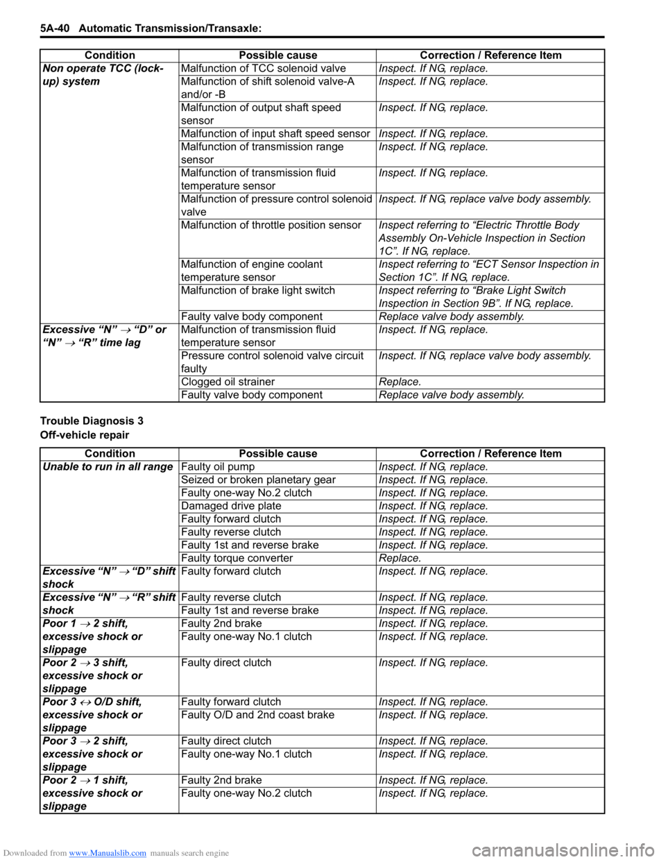
Trouble Diagnosis 3
Off-vehicle repairNon operate TCC (lock-
up) system
Malfunction of TCC solenoid valve
Inspect. If NG, replace.
Malfunction of shift solenoid valve-A
and/or -B Inspect. If NG, replace.
Malfunction of output shaft speed
sensor Inspect. If NG, replace.
Malfunction of input shaft speed sensor Inspect. If NG, replace.
Malfunction of transmission range
sensor Inspect. If NG, replace.
Malfunction of transmission fluid
temperature sensor Inspect. If NG, replace.
Malfunction of pressure control solenoid
valve Inspect. If NG, replace valve body assembly.
Malfunction of throttle position sensor Inspect referring to “Electric Throttle Body
Assembly On-Vehicle Inspection in Section
1C”. If NG, replace.
Malfunction of engine coolant
temperature sensor Inspect referring to “ECT Sensor Inspection in
Section 1C”. If NG, replace.
Malfunction of brake light switch Inspect referring to “Brake Light Switch
Inspection in Section 9B”. If NG, replace.
Faulty valve body component Replace valve body assembly.
Excessive “N”
→ “D” or
“N”
→ “R” time lag Malfunction of transmission fluid
temperature sensor Inspect. If NG, replace.
Pressure control solenoid valve circuit
faulty Inspect. If NG, replace valve body assembly.
Clogged oil strainer Replace.
Faulty valve body component Replace valve body assembly.
Condition Possible cause Correction / Reference Item
Condition
Possible cause Correction / Reference Item
Unable to run in all range Faulty oil pump Inspect. If NG, replace.
Seized or broken planetary gear Inspect. If NG, replace.
Faulty one-way No.2 clutch Inspect. If NG, replace.
Damaged drive plate Inspect. If NG, replace.
Faulty forward clutch Inspect. If NG, replace.
Faulty reverse clutch Inspect. If NG, replace.
Faulty 1st and reverse brake Inspect. If NG, replace.
Faulty torque converter Replace.
Excessive “N”
→ “D” shift
shock Faulty forward clutch
Inspect. If NG, replace.
Excessive “N”
→ “R” shift
shock Faulty reverse clutch
Inspect. If NG, replace.
Faulty 1st and reverse brake Inspect. If NG, replace.
Poor 1
→ 2 shift,
excessive shock or
slippage Faulty 2nd brake
Inspect. If NG, replace.
Faulty one-way No.1 clutch Inspect. If NG, replace.
Poor 2
→ 3 shift,
excessive shock or
slippage Faulty direct clutch
Inspect. If NG, replace.
Poor 3
↔ O/D shift,
excessive shock or
slippage Faulty forward clutch
Inspect. If NG, replace.
Faulty O/D and 2nd coast brake Inspect. If NG, replace.
Poor 3
→ 2 shift,
excessive shock or
slippage Faulty direct clutch
Inspect. If NG, replace.
Faulty one-way No.1 clutch Inspect. If NG, replace.
Poor 2
→ 1 shift,
excessive shock or
slippage Faulty 2nd brake
Inspect. If NG, replace.
Faulty one-way No.2 clutch Inspect. If NG, replace.
Page 685 of 1496
Downloaded from www.Manualslib.com manuals search engine Automatic Transmission/Transaxle: 5A-41
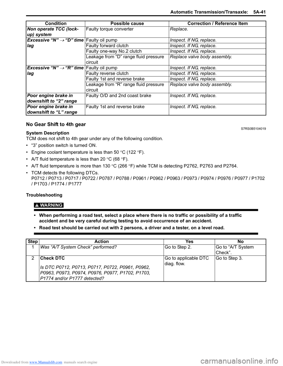
No Gear Shift to 4th gearS7RS0B5104019
System Description
TCM does not shift to 4th gear under any of the following condition.
• “3” position switch is turned ON.
• Engine coolant temperature is less than 50 °C (122 °F).
• A/T fluid temperature is less than 20 °C (68 °F).
• A/T fluid temperature is more than 130 °C (266 °F) while TCM is detecting P2762, P2763 and P2764.
• TCM detects the following DTCs. P0712 / P0713 / P0717 / P0722 / P0787 / P0788 / P0961 / P0962 / P0963 / P0973 / P0974 / P0976 / P0977 / P1702
/ P1703 / P1774 / P1777
Troubleshooting
WARNING!
• When performing a road test, select a place where there is no traffic or possibility of a traffic accident and be very careful during testing to avoid occurrence of an accident.
• Road test should be carried out with 2 persons, a driver and a tester, on a level road.
Non operate TCC (lock-
up) system Faulty torque converter
Replace.
Excessive “N”
→ “D” time
lag Faulty oil pump
Inspect. If NG, replace.
Faulty forward clutch Inspect. If NG, replace.
Faulty one-way No.2 clutch Inspect. If NG, replace.
Leakage from “D” range fluid pressure
circuit Replace valve body assembly.
Excessive “N”
→ “R” time
lag Faulty oil pump
Inspect. If NG, replace.
Faulty reverse clutch Inspect. If NG, replace.
Faulty 1st and reverse brake Inspect. If NG, replace.
Leakage from “R” range fluid pressure
circuit Replace valve body assembly.
Poor engine brake in
downshift to “2” range Faulty O/D and 2nd coast brake
Inspect. If NG, replace.
Poor engine brake in
downshift to “L” range Faulty 1st and reverse brake
Inspect. If NG, replace.
Condition Possible cause Correction / Reference Item
Step
Action YesNo
1 Was “A/T System Check” performed? Go to Step 2.Go to “A/T System
Check”.
2 Check DTC
Is DTC P0712, P0713, P0717, P0722, P0961, P0962,
P0963, P0973, P0974, P0976, P0977, P1702, P1703,
P1774 and/or P1777 detected? Go to applicable DTC
diag. flow.
Go to Step 3.
Page 827 of 1496
Downloaded from www.Manualslib.com manuals search engine Manual Transmission/Transaxle: 5B-13
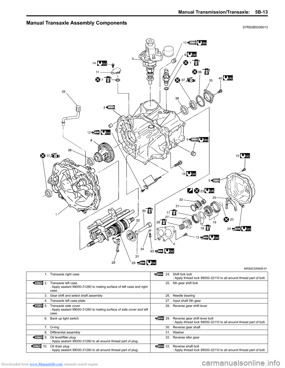
Manual Transaxle Assembly ComponentsS7RS0B5206013
I6RS0C520005-01
1. Transaxle right case 24. Shift fork bolt
: Apply thread lock 99000-32110 to all around thread part of bolt.
2. Transaxle left case : Apply sealant 99000-31260 to mating surface of left case and right
case. 25. 5th gear shift fork
3. Gear shift and select shaft assembly 26. Needle bearing
4. Transaxle left case plate 27. Input shaft 5th gear
5. Transaxle side cover : Apply sealant 99000-31260 to mating surface of side cover and left
case. 28. Reverse gear shift lever
6. Back up light switch 29. Reverse gear shift lever bolt
: Apply thread lock 99000-32110 to all around thread part of bolt.
7. O-ring 30. Reverse gear shaft
8. Differential assembly 31. Washer
9. Oil level/filler plug : Apply sealant 99000-31260 to all around thread part of plug. 32. Reverse idler gear
10. Oil drain plug : Apply sealant 99000-31260 to all around thread part of plug. 33. Reverse shaft bolt
: Apply thread lock 99000-32110 to all around thread part of bolt.
Page 831 of 1496
Downloaded from www.Manualslib.com manuals search engine Manual Transmission/Transaxle: 5B-17
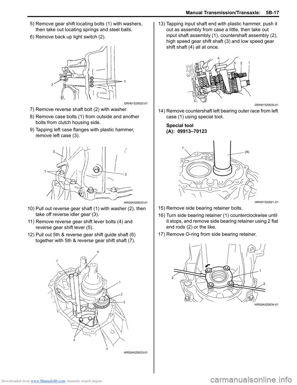
5) Remove gear shift locating bolts (1) with washers,
then take out locating springs and steel balls.
6) Remove back up light switch (2).
7) Remove reverse shaft bolt (2) with washer.
8) Remove case bolts (1) from outside and another bolts from clutch housing side.
9) Tapping left case flanges with plastic hammer, remove left case (3).
10) Pull out reverse gear shaft (1) with washer (2), then take off reverse idler gear (3).
11) Remove reverse gear shift lever bolts (4) and reverse gear shift lever (5).
12) Pull out 5th & reverse gear shift guide shaft (6) together with 5th & reverse gear shift shaft (7). 13) Tapping input shaft end with plastic hammer, push it
out as assembly from case a little, then take out
input shaft assembly (1), countershaft assembly (2),
high speed gear shift shaft (3) and low speed gear
shift shaft (4) all at once.
14) Remove countershaft left bearing outer race from left case (1) using special tool.
Special tool
(A): 09913–70123
15) Remove side bearing retainer bolts.
16) Turn side bearing retainer (1) counterclockwise until it stops, and remove side bearing retainer using 2 flat
end rods (2) or the like.
17) Remove O-ring from side bearing retainer.
I2RH01520032-01
I4RS0A520032-01
I4RS0A520033-01
I2RH01520035-01
(A)
1
I4RH01520021-01
1
2
2
I4RS0A520034-01
Page 836 of 1496
Downloaded from www.Manualslib.com manuals search engine 5B-22 Manual Transmission/Transaxle:
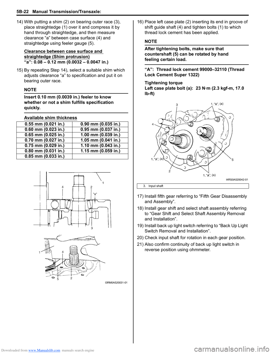
14) With putting a shim (2) on bearing outer race (3), place straightedge (1) over it and compress it by
hand through straightedge, and then measure
clearance “a” between case surface (4) and
straightedge using feeler gauge (5).
Clearance between case surface and
straightedge (Shim protrusion)
“a”: 0.08 – 0.12 mm (0.0032 – 0.0047 in.)
15) By repeating Step 14), select a suitable shim which adjusts clearance “a” to specification and put it on
bearing outer race.
NOTE
Insert 0.10 mm (0.0039 in.) feeler to know
whether or not a shim fulfills specification
quickly.
Available shim thickness
16) Place left case plate (2) inserting its end in groove of shift guide shaft (4) and tighten bolts (1) to which
thread lock cement has been applied.
NOTE
After tightening bolts, make sure that
countershaft (5) can be rotated by hand
feeling certain load.
“A”: Thread lock cement 99000–32110 (Thread
Lock Cement Super 1322)
Tightening torque
Left case plate bolt (a): 23 N·m (2.3 kgf-m, 17.0
lb-ft)
17) Install fifth gear referring to “Fifth Gear Disassembly and Assembly”.
18) Install gear shift and select shaft assembly referring to “Gear Shift and Select Shaft Assembly Removal
and Installation”.
19) Install back up light switch referring to “Back Up Light
Switch Removal and Installation”.
20) Check input shaft for rotation in each gear position.
21) Also confirm continuity of back up light switch in
reverse position using ohmmeter.
0.55 mm (0.021 in.) 0.90 mm (0.035 in.)
0.60 mm (0.023 in.) 0.95 mm (0.037 in.)
0.65 mm (0.025 in.) 1.00 mm (0.039 in.)
0.70 mm (0.027 in.) 1.05 mm (0.041 in.)
0.75 mm (0.029 in.) 1.10 mm (0.043 in.)
0.80 mm (0.031 in.) 1.15 mm (0.059 in.)
0.85 mm (0.033 in.)
I3RM0A520031-01
3. Input shaft
I4RS0A520042-01
Page 849 of 1496
Downloaded from www.Manualslib.com manuals search engine Manual Transmission/Transaxle: 5B-35
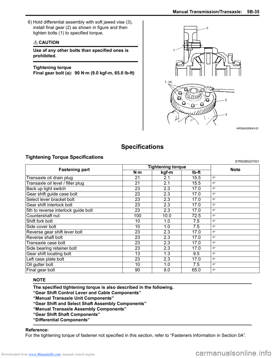
6) Hold differential assembly with soft jawed vise (3),
install final gear (2) as shown in figure and then
tighten bolts (1) to specified torque.
CAUTION!
Use of any other bolts than specified ones is
prohibited.
Tightening torque
Final gear bolt (a): 90 N·m (9.0 kgf-m, 65.0 lb-ft)
Specifications
Tightening Torque SpecificationsS7RS0B5207001
NOTE
The specified tightening torque is also described in the following.
“Gear Shift Control Leve r and Cable Components”
“Manual Transaxle Unit Components”
“Gear Shift and Select Shaft Assembly Components”
“Manual Transaxle Assembly Components”
“Gear Shift Shaft Components”
“Differential Components”
Reference:
For the tightening torque of fastener not specified in this section, refer to “Fasteners Information in Section 0A”.
I4RS0A520043-01
Fastening part Tightening torque
Note
N ⋅mkgf-mlb-ft
Transaxle oil drain plug 21 2.1 15.5 �)
Transaxle oil level / filler plug 21 2.1 15.5 �)
Back up light switch 23 2.3 17.0 �)
Gear shift guide case bolt 23 2.3 17.0 �)
Select lever bracket bolt 23 2.3 17.0 �)
Gear shift interlock bolt 23 2.3 17.0 �)
5th to reverse interlock guide bolt 23 2.3 17.0 �)
Countershaft nut 100 10.0 72.5 �)
Shift fork bolt 10 1.0 7.5 �)
Side cover bolt 10 1.0 7.5 �)
Reverse gear shift lever bolt 23 2.3 17.0 �)
Reverse shaft bolt 23 2.3 17.0 �)
Transaxle case bolt 23 2.3 17.0 �)
Side bearing retainer bolt 23 2.3 17.0 �)
Gear shift locating bolt 13 1.3 9.5 �)
Left case plate bolt 23 2.3 17.0 �)
Oil gutter bolt 10 1.0 7.5 �)
Final gear bolt 90 9.0 65.0 �)
Page 928 of 1496
Downloaded from www.Manualslib.com manuals search engine 6C-46 Power Assisted Steering System:
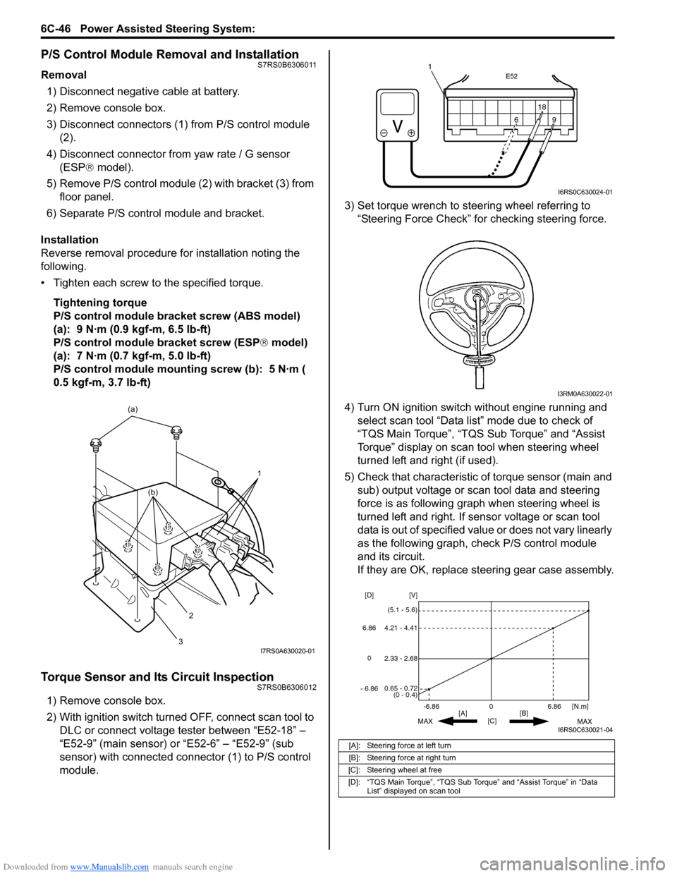
P/S Control Module Removal and InstallationS7RS0B6306011
Removal1) Disconnect negative cable at battery.
2) Remove console box.
3) Disconnect connectors (1) from P/S control module (2).
4) Disconnect connector from yaw rate / G sensor
(ESP ® model).
5) Remove P/S control module (2) with bracket (3) from floor panel.
6) Separate P/S control module and bracket.
Installation
Reverse removal procedure for installation noting the
following.
• Tighten each screw to the specified torque. Tightening torque
P/S control module bracket screw (ABS model)
(a): 9 N·m (0.9 kgf-m, 6.5 lb-ft)
P/S control module bracket screw (ESP ® model)
(a): 7 N·m (0.7 kgf-m, 5.0 lb-ft)
P/S control module mounting screw (b): 5 N·m (
0.5 kgf-m, 3.7 lb-ft)
Torque Sensor and Its Circuit InspectionS7RS0B6306012
1) Remove console box.
2) With ignition switch turned OFF, connect scan tool to DLC or connect voltage tester between “E52-18” –
“E52-9” (main sensor) or “E52-6” – “E52-9” (sub
sensor) with connected connector (1) to P/S control
module. 3) Set torque wrench to stee
ring wheel referring to
“Steering Force Check” for checking steering force.
4) Turn ON ignition switch without engine running and select scan tool “Data list” mode due to check of
“TQS Main Torque”, “TQS Sub Torque” and “Assist
Torque” display on scan tool when steering wheel
turned left and right (if used).
5) Check that characteristic of torque sensor (main and sub) output voltage or scan tool data and steering
force is as following graph when steering wheel is
turned left and right. If sensor voltage or scan tool
data is out of specified value or does not vary linearly
as the following graph, check P/S control module
and its circuit.
If they are OK, replace steering gear case assembly.
1
(a)
2
3
(b)
I7RS0A630020-01
[A]: Steering force at left turn
[B]: Steering force at right turn
[C]: Steering wheel at free
[D]: “TQS Main Torque”, “TQS Sub Torque” and “Assist Torque” in “Data List” displayed on scan tool
E52
18
9
6
9
6 18
1
I6RS0C630024-01
I3RM0A630022-01
0
[C] [N.m]
MAX MAX
[B]
[A]
2.33 - 2.68 [V]
[D]
0.65 - 0.72
(0 - 0.4)
4.21 - 4.41
(5.1 - 5.6)
6.86
-6.86
0
6.86
- 6.86
I6RS0C630021-04