transmission replacement SUZUKI SWIFT 2008 2.G Service User Guide
[x] Cancel search | Manufacturer: SUZUKI, Model Year: 2008, Model line: SWIFT, Model: SUZUKI SWIFT 2008 2.GPages: 1496, PDF Size: 34.44 MB
Page 818 of 1496
Downloaded from www.Manualslib.com manuals search engine 5B-4 Manual Transmission/Transaxle:
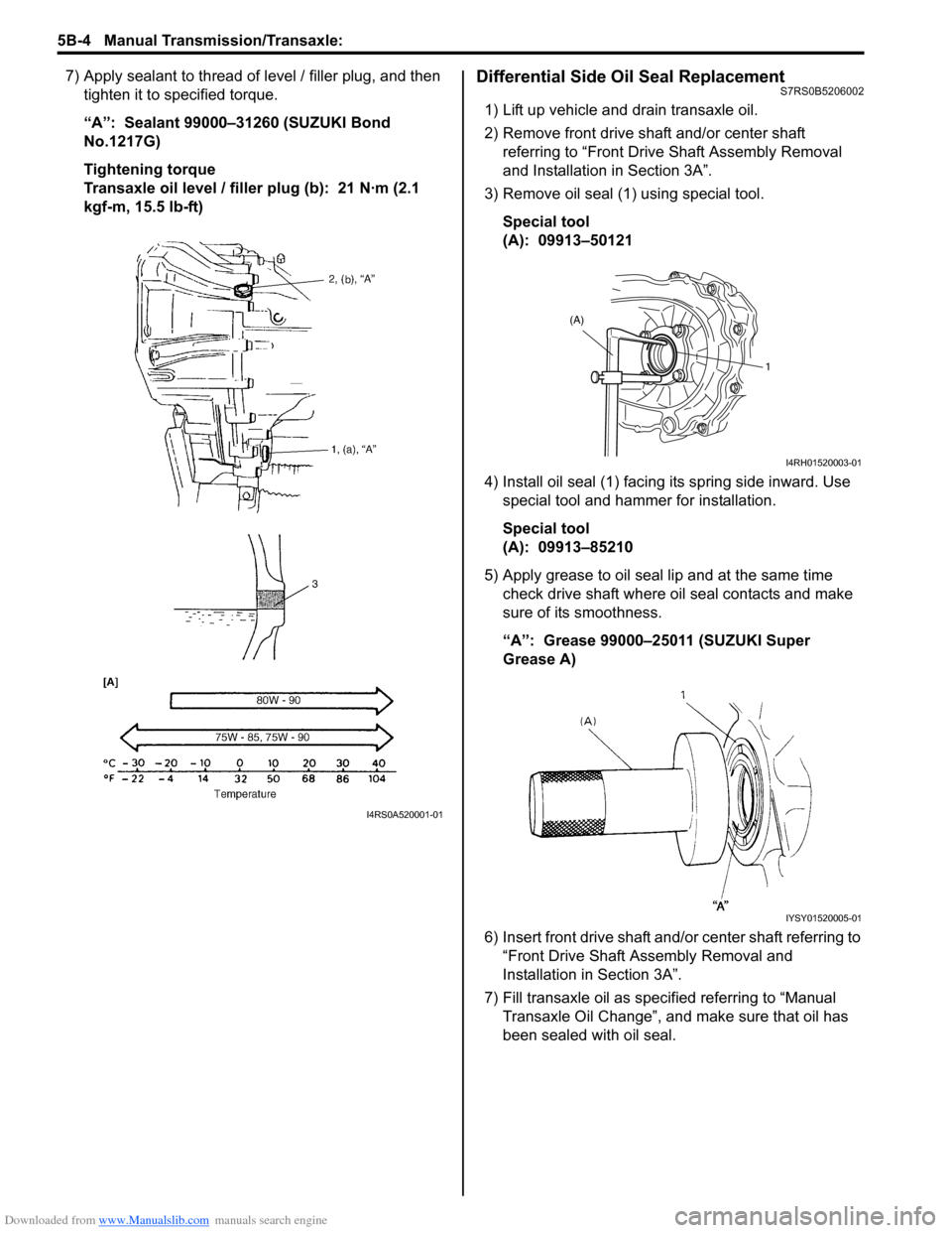
7) Apply sealant to thread of level / filler plug, and then
tighten it to specified torque.
“A”: Sealant 99000–31260 (SUZUKI Bond
No.1217G)
Tightening torque
Transaxle oil level / filler plug (b): 21 N·m (2.1
kgf-m, 15.5 lb-ft)Differential Side Oil Seal ReplacementS7RS0B5206002
1) Lift up vehicle and drain transaxle oil.
2) Remove front drive shaft and/or center shaft referring to “Front Driv e Shaft Assembly Removal
and Installation in Section 3A”.
3) Remove oil seal (1) using special tool.
Special tool
(A): 09913–50121
4) Install oil seal (1) facing its spring side inward. Use special tool and hammer for installation.
Special tool
(A): 09913–85210
5) Apply grease to oil seal lip and at the same time check drive shaft where oil seal contacts and make
sure of its smoothness.
“A”: Grease 99000–25011 (SUZUKI Super
Grease A)
6) Insert front drive shaft and/or center shaft referring to “Front Drive Shaft A ssembly Removal and
Installation in Section 3A”.
7) Fill transaxle oil as specified referring to “Manual Transaxle Oil Change”, and make sure that oil has
been sealed with oil seal.
I4RS0A520001-01
(A)
1
I4RH01520003-01
IYSY01520005-01
Page 837 of 1496
Downloaded from www.Manualslib.com manuals search engine Manual Transmission/Transaxle: 5B-23
Transaxle Right Case Disassembly and
Assembly
S7RS0B5206016
Disassembly1) Remove gear shift shaft, input shaft assembly and countershaft assembly referring to “Manual
Transaxle Assembly Disassembly and Reassembly”.
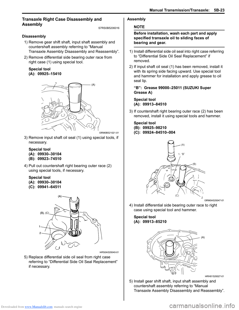
2) Remove differential side bearing outer race from right case (1) using special tool.
Special tool
(A): 09925–15410
3) Remove input shaft oil seal (1) using special tools, if necessary.
Special tool
(A): 09930–30104
(B): 09923–74510
4) Pull out countershaft right bearing outer race (2) using special tools, if necessary.
Special tool
(A): 09930–30104
(C): 09941–64511
5) Replace differential side oil seal from right case referring to “Differential Side Oil Seal Replacement”
if necessary. Assembly
NOTE
Before installation, wash each part and apply
specified transaxle oil to sliding faces of
bearing and gear.
1) Install differential side oil seal into right case referring
to “Differential Side O il Seal Replacement” if
removed.
2) If input shaft oil seal (1) has been removed, install it with its spring side facing upward. Use special tool
and hammer for installation and apply grease to oil
seal lip.
“B”: Grease 99000–25011 (SUZUKI Super
Grease A)
Special tool
(A): 09913–84510
3) If countershaft right bearing outer race (2) has been removed, install it using special tools and hammer.
Special tool
(B): 09925–98210
(C): 09924–84510–004
4) Install differential side bearing outer race to right case using special tool and hammer.
Special tool
(A): 09913–85210
5) Install gear shift shaft, input shaft assembly and countershaft assembly referring to “Manual
Transaxle Assembly Disassembly and Reassembly”.
(A)1
I3RM0B521021-01
I4RS0A520040-01
I3RM0A520047-01
(A)
I4RH01520027-01
Page 838 of 1496
Downloaded from www.Manualslib.com manuals search engine 5B-24 Manual Transmission/Transaxle:
Transaxle Left Case Disassembly and AssemblyS7RS0B5206017
Disassembly1) Replace differential side oil seal from left case referri ng to “Differential Side Oil Seal Replacement”, if necessary.
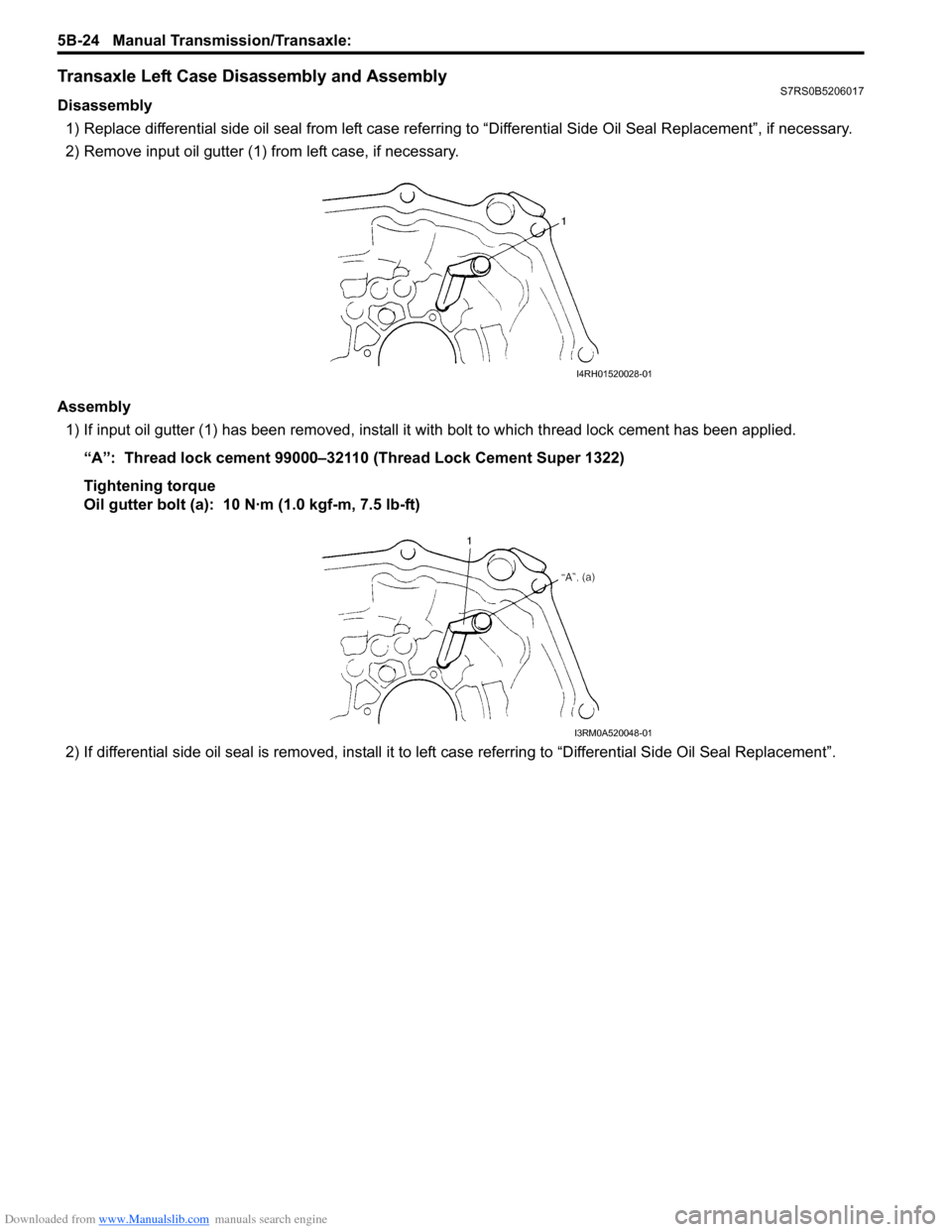
2) Remove input oil gutter (1) from left case, if necessary.
Assembly 1) If input oil gutter (1) has been removed, install it with bolt to which thread lock cement has been applied.
“A”: Thread lock cement 99000–32110 (Thread Lock Cement Super 1322)
Tightening torque
Oil gutter bolt (a): 10 N·m (1.0 kgf-m, 7.5 lb-ft)
2) If differential side oil seal is remov ed, install it to left case referring to “Differential Side Oil Seal Replacement”.
I4RH01520028-01
I3RM0A520048-01
Page 845 of 1496
Downloaded from www.Manualslib.com manuals search engine Manual Transmission/Transaxle: 5B-31
Synchronizer Parts InspectionS7RS0B5206021
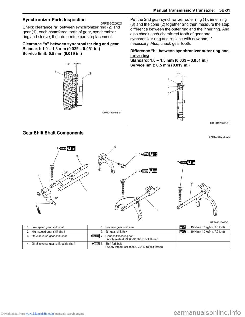
Check clearance “a” between synchronizer ring (2) and
gear (1), each chamfered tooth of gear, synchronizer
ring and sleeve, then determine parts replacement.
Clearance “a” between synchronizer ring and gear
Standard: 1.0 – 1.3 mm (0.039 – 0.051 in.)
Service limit: 0.5 mm (0.019 in.)Put the 2nd gear synchronizer outer ring (1), inner ring
(3) and the cone (2) together and then measure the step
difference between the outer ring and the inner ring. And
also check each chamfered tooth of gear and
synchronizer ring and replace with new one, if
necessary. Also, check gear tooth.
Difference “b” between synchronizer outer ring and
inner ring
Standard: 1.0 – 1.3 mm (0.039 – 0.051 in.)
Service limit: 0.5 mm (0.019 in.)
Gear Shift Shaft ComponentsS7RS0B5206022
I2RH01520048-01
I2RH01520059-01
5
3
4 6
1
2
8
7
77
(a)
(b)
(a)
(a)
I4RS0A520015-01
1. Low speed gear shift shaft
5. Reverse gear shift arm : 13 N⋅m (1.3 kgf-m, 9.5 lb-ft)
2. High speed gear shift shaft 6. 5th gear shift fork : 10 N⋅m (1.0 kgf-m, 7.5 lb-ft)
3. 5th & reverse gear shift shaft 7. Gear shift locating bolt
: Apply sealant 99000-31260 to bolt thread.
4. 5th & reverse gear shift guide shaft 8. Shift fork bolt
: Apply thread lock 99000-32110 to bolt thread.
Page 846 of 1496
Downloaded from www.Manualslib.com manuals search engine 5B-32 Manual Transmission/Transaxle:
5th and Reverse Gear Shift Shafts Disassembly
and Assembly
S7RS0B5206023
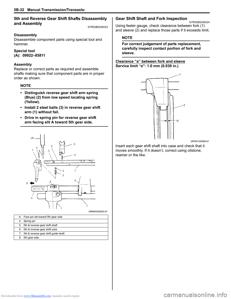
Disassembly
Disassemble component parts using special tool and
hammer.
Special tool
(A): 09922–85811
Assembly
Replace or correct parts as required and assemble
shafts making sure that component parts are in proper
order as shown.
NOTE
• Distinguish reverse gear shift arm spring (Blue) (2) from low speed locating spring
(Yellow).
• Install 2 steel balls (3) in reverse gear shift arm (1) without fail.
• Drive in spring pin for reverse gear shift arm facing slit A toward 5th gear side.
Gear Shift Shaft and Fork InspectionS7RS0B5206024
Using feeler gauge, check clearance between fork (1)
and sleeve (2) and replace those parts if it exceeds limit.
NOTE
For correct judgement of parts replacement,
carefully inspect contact portion of fork and
sleeve.
Clearance “a” between fork and sleeve
Service limit “a”: 1.0 mm (0.039 in.)
Insert each gear shift shaft into case and check that it
moves smoothly. If it doesn’t, correct using oilstone,
reamer or the like.
A: Face pin slit toward 5th gear side
4. Spring pin
5. 5th & reverse gear shift shaft
6. 5th & reverse gear shift yoke
7. 5th & reverse gear shift guide shaft
8. 5th gear side
I3RM0A520053-01
I2RH01520068-01
Page 1470 of 1496
Downloaded from www.Manualslib.com manuals search engine 10E-8 Keyless Start System:
Diagnostic Information and Procedures
Precautions in Diagnosing TroublesS7RS0BA504001
• The keyless start system executes data transmission/reception by means of th e radio wave. Therefore,
proper operation may not be obtained if use of the
door lock function and engine start function of the
keyless start system is attempted near the place
where strong radio wave is emitted (TV and radio
broadcasting stations, etc.).
• Diagnostic information stored in keyless start control
module memory can be checked only by key indicator
lamp.
• Be sure to use the trouble diagnosis procedure as described in “Keyless Start System Check”. Failure to
follow it may result in incorrect diagnosis. (Some other
DTC may be stored by mistake in the memory of
keyless start control module during inspection.)
• Be sure to read “Precautions for Electrical Circuit Service in Section 00” befo re inspection and observe
what is written there.
• Communication of ECM, BCM, TCM (A/T model), ABS control module, keyless start control module and
combination meter is estab lished by CAN (Controller
Area Network). (For detail of CAN communication for
keyless start control module, refer to “CAN
Communication System Description”). Therefore,
handle CAN communication line with care referring to
“Precaution for CAN Communication System in
Section 00”. • Replacement of the keyless start control module
When keyless start control module is replaced with
new one, make sure that r egister remote controller ID
code to keyless start co ntrol module correctly
according to “Registration Procedure for Remote
Controller ID Code”.
• Keyless start control module substitution When the keyless start control module used in
another vehicle was installed in the vehicle, register
the ID code of the remote controller in the keyless
start control module as well as the ignition key
transponder code fo r the immobilizer control system in
ECM. For the registration procedure of the ignition key
transponder code, refer to “Registration of the Ignition
Key in Section 10C”.
Self-Diagnosis FunctionS7RS0BA504002
The keyless start control module has self-diagnosis
function to monitor the system components and circuits
while the keyless start system is at work. When the
keyless start control module detects an abnormality in
the system, it saves the ar ea where such abnormality
has occurred as a DTC in its memory. The DTC stored in
memory of the keyless start control module is indicated
by the key indicator lamp in the combination meter
flashing in a specific pattern. For DTC indication, refer to
“DTC Check” and for the clearing procedure, to “DTC
Clearance”.
Keyless Start System Diagnosis IntroductionS7RS0BA504003
To ensure that the trouble diagnosis is done accurately
and smoothly, observe “Precautions in Diagnosing
Troubles” and follow “Keyless Start System Check”.
Keyless Start System CheckS7RS0BA504004
Step Action YesNo
1 1) Record details of the problem. For your record, use of a questionnaire form will facilit ate collecting information for
proper analysis and diagnosis.
2) Check if the problem described in “Customer Questionnaire (Example)” actually occurs in the vehicle.
(This step should be performed with the customer if
possible.)
Perform “Keyless Start System Operation Inspection”
procedure to check if the symptom which has occurred is
abnormal or not.
3) Check for DTC referring to “DTC Check”, and then record DTC(s).
4) Clear DTC referring to “DTC Clearance” if any DTC exists, and then recheck for DTC.
Is any DTC still detected? Go to Step 2.
Go to Step 3.
2 1) Check and repair referring to applicable “DTC Table”. Are check and repair complete? Go to Step 5.
Check and repair
malfunction part(s), and
go to Step 5.
Page 1494 of 1496
Downloaded from www.Manualslib.com manuals search engine 10E-32 Keyless Start System:
Keyless Start Control Module Removal and
Installation
S7RS0BA506006
Removal1) Disconnect negative (–) cable at battery.
2) Remove glove box from instrument panel.
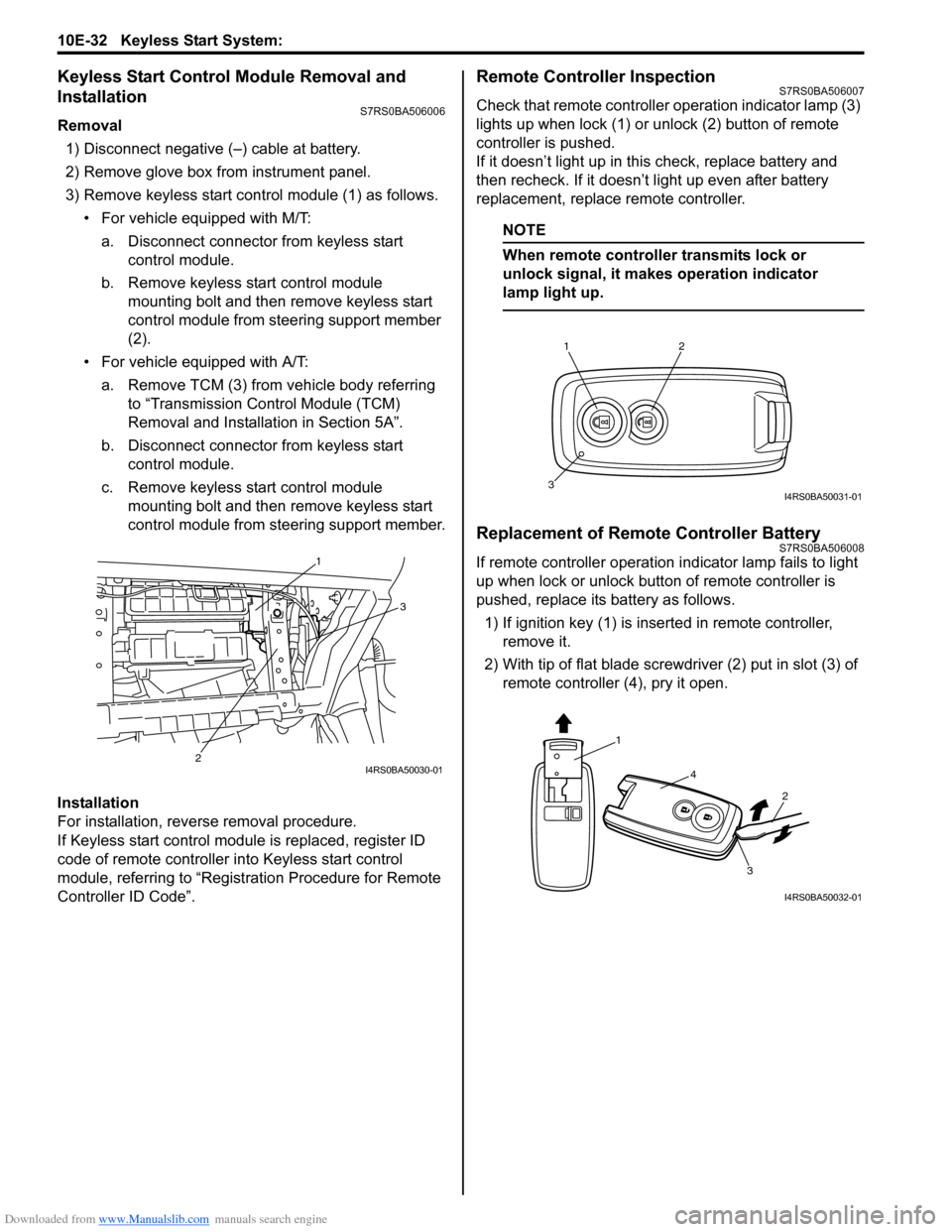
3) Remove keyless start cont rol module (1) as follows.
• For vehicle equipped with M/T:
a. Disconnect connector from keyless start control module.
b. Remove keyless start control module mounting bolt and then remove keyless start
control module from steering support member
(2).
• For vehicle equipped with A/T: a. Remove TCM (3) from vehicle body referring to “Transmission Control Module (TCM)
Removal and Installation in Section 5A”.
b. Disconnect connector from keyless start control module.
c. Remove keyless start control module mounting bolt and then remove keyless start
control module from steering support member.
Installation
For installation, reverse removal procedure.
If Keyless start control module is replaced, register ID
code of remote controller in to Keyless start control
module, referring to “Registration Procedure for Remote
Controller ID Code”.
Remote Controller InspectionS7RS0BA506007
Check that remote controller operation indicator lamp (3)
lights up when lock (1) or un lock (2) button of remote
controller is pushed.
If it doesn’t light up in this check, replace battery and
then recheck. If it doesn’t light up even after battery
replacement, replace remote controller.
NOTE
When remote controller transmits lock or
unlock signal, it makes operation indicator
lamp light up.
Replacement of Remote Controller BatteryS7RS0BA506008
If remote controller operation i ndicator lamp fails to light
up when lock or unlock button of remote controller is
pushed, replace its battery as follows.
1) If ignition key (1) is inse rted in remote controller,
remove it.
2) With tip of flat blade screwdriver (2) put in slot (3) of remote controller (4), pry it open.1
3
2
I4RS0BA50030-01
12
3I4RS0BA50031-01
1
4
2
3
I4RS0BA50032-01