Engine construction SUZUKI SWIFT 2008 2.G Service Owner's Manual
[x] Cancel search | Manufacturer: SUZUKI, Model Year: 2008, Model line: SWIFT, Model: SUZUKI SWIFT 2008 2.GPages: 1496, PDF Size: 34.44 MB
Page 500 of 1496
Downloaded from www.Manualslib.com manuals search engine 4A-2 Brake Control System and Diagnosis:
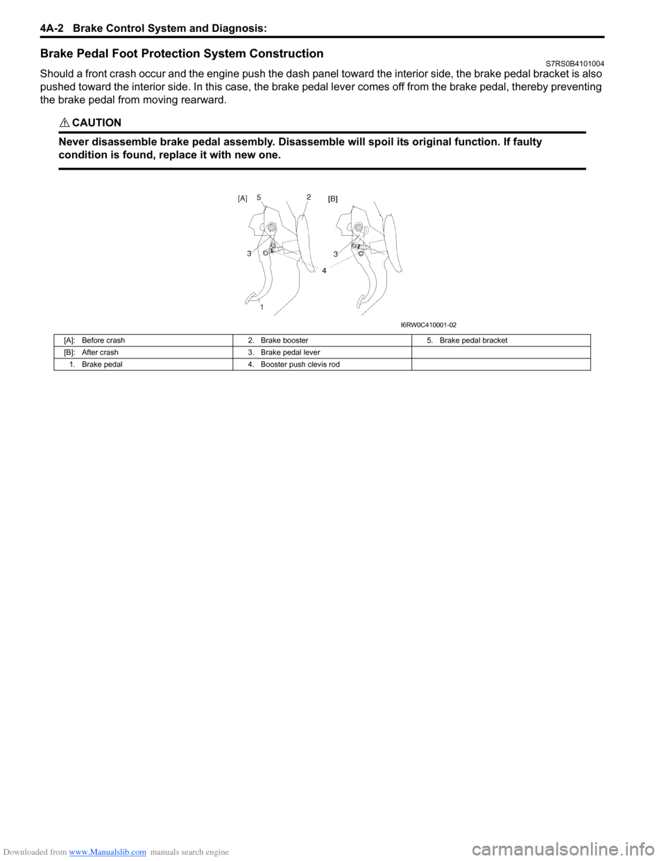
Brake Pedal Foot Protection System ConstructionS7RS0B4101004
Should a front crash occur and the engine push the dash panel toward the interior side, the brake pedal bracket is also
pushed toward the interior side. In this case, the brake pedal lever comes off from the brake pedal, thereby preventing
the brake pedal from moving rearward.
CAUTION!
Never disassemble brake pedal assembly. Disassemble will spoil its original function. If faulty
condition is found, replace it with new one.
[A]: Before crash2. Brake booster5. Brake pedal bracket
[B]: After crash 3. Brake pedal lever
1. Brake pedal 4. Booster push clevis rod
I6RW0C410001-02
Page 501 of 1496
Downloaded from www.Manualslib.com manuals search engine Brake Control System and Diagnosis: 4A-3
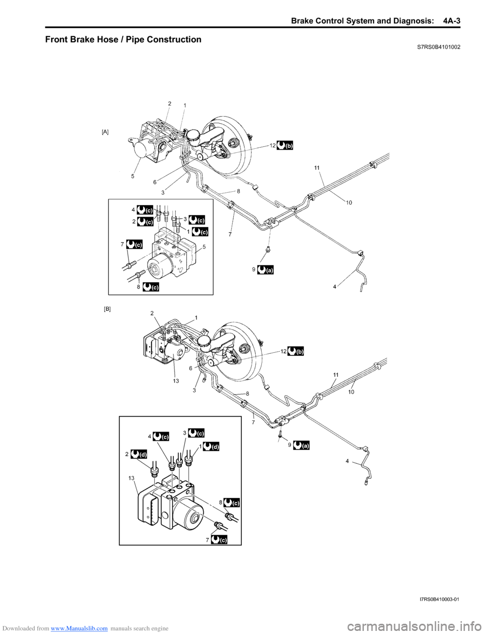
Front Brake Hose / Pipe ConstructionS7RS0B4101002
I7RS0B410003-01
Page 502 of 1496
Downloaded from www.Manualslib.com manuals search engine 4A-4 Brake Control System and Diagnosis:
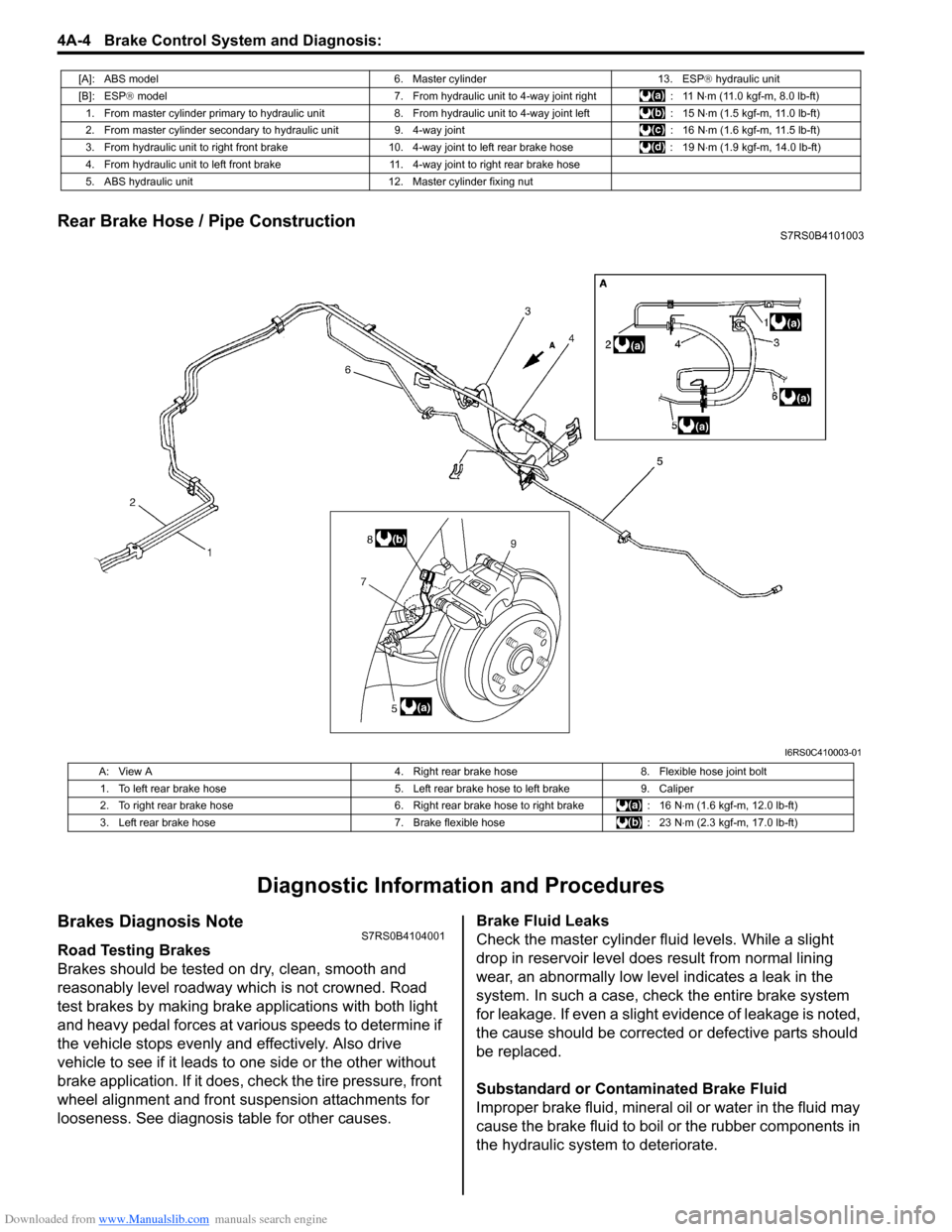
Rear Brake Hose / Pipe ConstructionS7RS0B4101003
Diagnostic Information and Procedures
Brakes Diagnosis NoteS7RS0B4104001
Road Testing Brakes
Brakes should be tested on dry, clean, smooth and
reasonably level roadway which is not crowned. Road
test brakes by making brake applications with both light
and heavy pedal forces at vari ous speeds to determine if
the vehicle stops evenly and effectively. Also drive
vehicle to see if it leads to one side or the other without
brake application. If it does, check the tire pressure, front
wheel alignment and front suspension attachments for
looseness. See diagnosis table for other causes. Brake Fluid Leaks
Check the master cylinder fl
uid levels. While a slight
drop in reservoir level does result from normal lining
wear, an abnormally low leve l indicates a leak in the
system. In such a case, chec k the entire brake system
for leakage. If even a slight ev idence of leakage is noted,
the cause should be corrected or defective parts should
be replaced.
Substandard or Contaminated Brake Fluid
Improper brake fluid, mineral oil or water in the fluid may
cause the brake fluid to boil or the rubber components in
the hydraulic system to deteriorate.
[A]: ABS model 6. Master cylinder13. ESP® hydraulic unit
[B]: ESP ® model 7. From hydraulic unit to 4-way joint right : 11 N⋅m (11.0 kgf-m, 8.0 lb-ft)
1. From master cylinder primary to hydraulic unit 8. From hydraulic unit to 4-way joint left: 15 N⋅m (1.5 kgf-m, 11.0 lb-ft)
2. From master cylinder secondary to hydraulic unit 9. 4-way joint: 16 N⋅m (1.6 kgf-m, 11.5 lb-ft)
3. From hydraulic unit to right front brake 10.4-way joint to left rear brake hose : 19 N⋅m (1.9 kgf-m, 14.0 lb-ft)
4. From hydraulic unit to left front brake 11. 4-way joint to right rear brake hose
5. ABS hydraulic unit 12. Master cylinder fixing nut
I6RS0C410003-01
A: View A4. Right rear brake hose8. Flexible hose joint bolt
1. To left rear brake hose 5. Left rear brake hose to left brake9. Caliper
2. To right rear brake hose 6. Right rear brake hose to right brake: 16 N⋅m (1.6 kgf-m, 12.0 lb-ft)
3. Left rear brake hose 7. Brake flexible hose: 23 N⋅m (2.3 kgf-m, 17.0 lb-ft)
Page 508 of 1496
Downloaded from www.Manualslib.com manuals search engine 4A-10 Brake Control System and Diagnosis:
7) Then attach bleeder plug cap.
8) After completing bleeding operation, apply fluid pressure to pipe line and check for leakage.
9) Replenish fluid into reserv oir up to specified level.
10) Check brake pedal for sponginess. If found spongy, repeat entire procedure of bleeding.
Front Brake Hose / Pipe Removal and
Installation
S7RS0B4106007
“Front Brake Hose / Pipe Construction”
CAUTION!
Do not allow brake fluid to get on painted
surfaces. Painted surfaces will be damaged
by brake fluid, flush it with water immediately
if any fluid is spilled.
Removal
1) Raise and support vehicle properly. Remove tire and wheel.
NOTE
This operation is not necessary when
removing pipes connecting master cylinder.
2) Clean dirt and foreign mate rial from both flexible
hose end and pipe end fittings.
3) Drain brake fluid in reservoir.
4) Remove brake flexible hose or pipe.
Installation
Reverse brake flexible hose removal procedure, noting
the following.
• Make sure that steering wh eel is in straight-forward
position and flexible hose has not twist or kink.
• Check to make sure that flexible hose doesn’t contact any part of suspension, both in extreme right and
extreme left turn conditions. If it does at any point,
remove and correct. Fill and maintain brake fluid level
in reservoir.
• Bleed brake system. Refer to “Air Bleeding of Brake System”.
• Perform brake test and check installed part for fluid leakage.
Rear Brake Hose / Pipe Removal and
Installation
S7RS0B4106008
CAUTION!
Do not allow brake fluid to get on painted
surfaces. Painted surfaces will be damaged
by brake fluid, flush it with water immediately
if any fluid is spilled.
Removal
1) Raise and support vehicle properly. Remove tire and wheel.
2) Clean dirt and foreign material from both flexible hose end and pipe end fittings.
3) Drain brake fluid in reservoir.
4) Remove brake flexible hose or pipe.
Installation
Reverse brake flexible hose removal procedure, noting
the following.
• Fill and maintain brake fluid level in reservoir.
• Bleed brake system. Refer to “Air Bleeding of Brake System”.
• Perform brake test and check each installed part for fluid leakage.
• Never reuse protector nut once removed. Be sure to use a new one.
• Install clamps properly referring to the figure and tighten bolts.
• When installing hose, make sure that it has no twist or
kink.
I4RS0B410006-01
Page 516 of 1496
Downloaded from www.Manualslib.com manuals search engine 4A-18 Brake Control System and Diagnosis:
10) Check pedal height and play referring to “Brake Pedal Free Height Inspection” and “Brake Pedal
Play Inspection”.
11) Check each installed part for fluid leakage and perform brake test.
12) Evacuate and charge refrigerant by referring to “Evacuating of A/C Syst em” and “Procedure of
Charging” under “Operation Procedure for
Refrigerant Charge in Section 7B” or “Operation
Procedure for Refrigerant Charge in Section 7B”.
Brake Booster Inspection and AdjustmentS7RS0B4106018
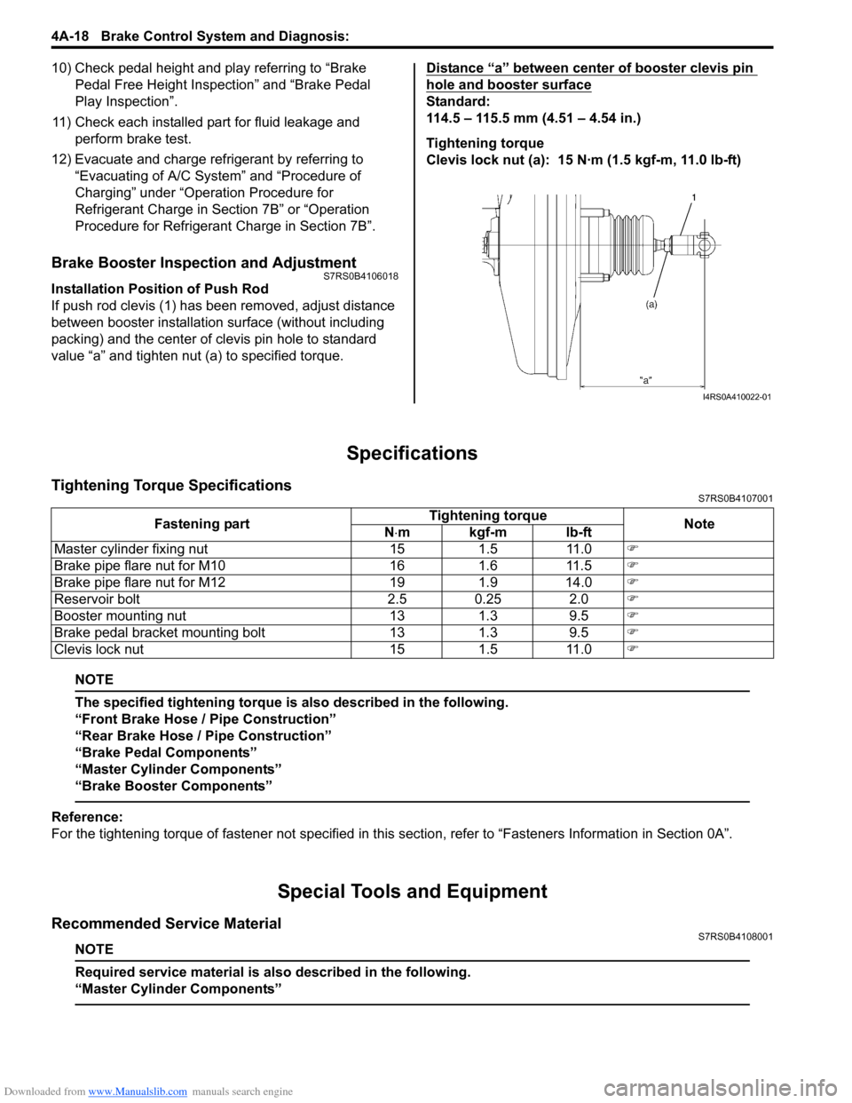
Installation Position of Push Rod
If push rod clevis (1) has b een removed, adjust distance
between booster installation surface (without including
packing) and the center of clevis pin hole to standard
value “a” and tighten nut (a) to specified torque. Distance “a” between center of booster clevis pin
hole and booster surface
Standard:
114.5 – 115.5 mm (4.51 – 4.54 in.)
Tightening torque
Clevis lock nut (a): 15 N·m (1.5 kgf-m, 11.0 lb-ft)
Specifications
Tightening Torque SpecificationsS7RS0B4107001
NOTE
The specified tightening torque is also described in the following.
“Front Brake Hose / Pipe Construction”
“Rear Brake Hose / Pipe Construction”
“Brake Pedal Components”
“Master Cylinder Components”
“Brake Booster Components”
Reference:
For the tightening torque of fastener not specified in this
section, refer to “Fasteners Information in Section 0A”.
Special Tools and Equipment
Recommended Service MaterialS7RS0B4108001
NOTE
Required service material is also described in the following.
“Master Cylinder Components”
I4RS0A410022-01
Fastening part Tightening torque
Note
N ⋅mkgf-mlb-ft
Master cylinder fixing nut 15 1.5 11.0 �)
Brake pipe flare nut for M10 16 1.6 11.5 �)
Brake pipe flare nut for M12 19 1.9 14.0 �)
Reservoir bolt 2.5 0.25 2.0 �)
Booster mounting nut 13 1.3 9.5 �)
Brake pedal bracket mounting bolt 13 1.3 9.5 �)
Clevis lock nut 15 1.5 11.0 �)
Page 536 of 1496
Downloaded from www.Manualslib.com manuals search engine 4D-1 Parking Brake:
Brakes
Parking Brake
General Description
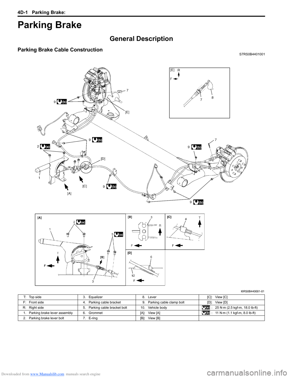
Parking Brake Cable ConstructionS7RS0B4401001
I6RS0B440001-01
T: Top side3. Equalizer8. Lever [C]: View [C]
F: Front side 4. Parking cable bracket9. Parking cable clamp bolt [D]: View [D]
R: Right side 5. Parking cable bracket bolt 10. Vehicle body : 25 N⋅m (2.5 kgf-m, 18.0 lb-ft)
1. Parking brake lever assembly 6. Grommet [A]: View [A]: 11 N⋅m (1.1 kgf-m, 8.0 lb-ft)
2. Parking brake lever bolt 7. E-ring[B]: View [B]
Page 538 of 1496
Downloaded from www.Manualslib.com manuals search engine 4D-3 Parking Brake:
6) Release parking brake lever and then make sure that there is no drag in rear wheel.
If there is, repeats go to step 2).
7) Make sure that the number of notch is between 4 and 9 when operating parking brake lever.
8) If the number of notch is not between 4 and 9, replace parking brake cable and/or inspect rear
brake caliper.
Parking brake stroke
When lever is pulled up at 200 N (20kg, 44lbs) : 4
to 9 notches
Parking Brake Cable Removal and InstallationS7RS0B4406002
Removal
NOTE
When it is necessary to remove both right
and left parking brake cables, repeat below
steps 2) and 5) on right and left wheels.
1) Hoist vehicle.
2) Remove wheel.
3) Disconnect parking brake cable from equalizer (parking brake lever) and clamps.
4) Disconnect parking brake cable from lever referring to “Rear Disc Brake Caliper Removal and Installation
in Section 4C”.
5) Remove parking brake cable and parking cable bracket.
Installation
Install it by reversing removal procedure, noting the
following points.
• Install clamps properly referring to “Parking Brake Cable Construction”.
• Tighten bolts and nuts to specified torque referring to “Parking Brake Cable Construction”.
Tightening torque
Parking brake lever bolt: 25 N·m (2.5 kgf-m, 18.0
lb-ft)
Parking cable clamp bolt: 11 N·m (1.1 kgf-m, 8.0
lb-ft)
Parking cable bracket bolt: 25 N·m (2.5 kgf-m,
18.0 lb-ft)
• Adjust parking brake cable. Refer to “Parking Brake Inspection and Adjustment”.
• Check brake disc for dragging and brake system for proper performance. Brake test should be performed.
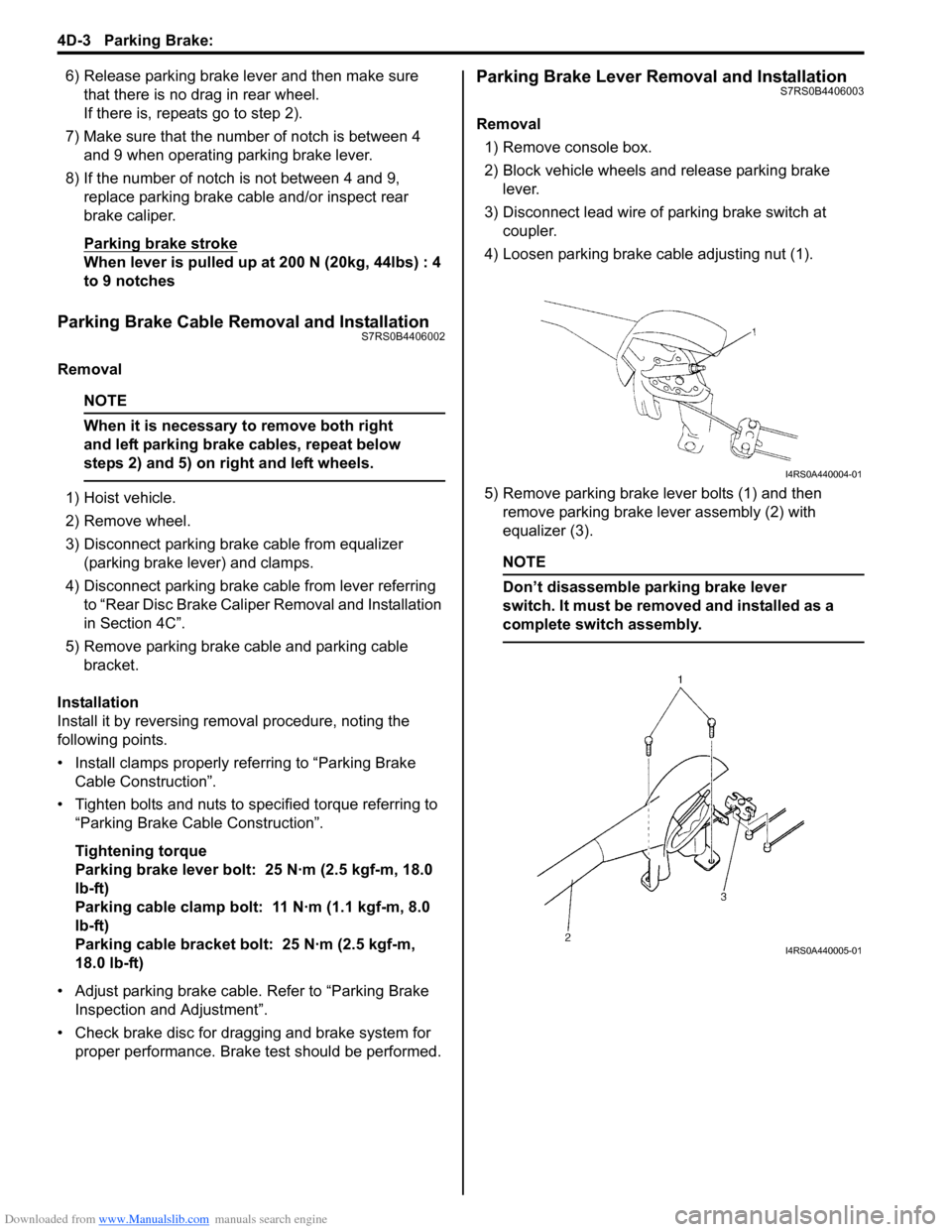
Parking Brake Lever Removal and InstallationS7RS0B4406003
Removal
1) Remove console box.
2) Block vehicle wheels and release parking brake lever.
3) Disconnect lead wire of parking brake switch at coupler.
4) Loosen parking brake cable adjusting nut (1).
5) Remove parking brake lever bolts (1) and then remove parking brake lever assembly (2) with
equalizer (3).
NOTE
Don’t disassemble parking brake lever
switch. It must be removed and installed as a
complete switch assembly.
I4RS0A440004-01
I4RS0A440005-01
Page 539 of 1496
Downloaded from www.Manualslib.com manuals search engine Parking Brake: 4D-4
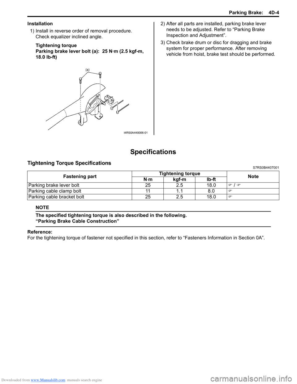
Installation1) Install in reverse order of removal procedure. Check equalizer inclined angle.
Tightening torque
Parking brake lever bolt (a): 25 N·m (2.5 kgf-m,
18.0 lb-ft) 2) After all parts are installed, parking brake lever
needs to be adjusted. Refer to “Parking Brake
Inspection and Adjustment”.
3) Check brake drum or disc for dragging and brake system for proper performance. After removing
vehicle from hoist, brake test should be performed.
Specifications
Tightening Torque SpecificationsS7RS0B4407001
NOTE
The specified tightening torque is also described in the following.
“Parking Brake Cable Construction”
Reference:
For the tightening torque of fastener not specified in this section, refer to “Fasteners Information in Section 0A”.
I4RS0A440006-01
Fastening part Tightening torque
Note
N ⋅mkgf-mlb-ft
Parking brake lever bolt 25 2.5 18.0 �) / �)
Parking cable clamp bolt 11 1.1 8.0 �)
Parking cable bracket bolt 25 2.5 18.0 �)
Page 577 of 1496
Downloaded from www.Manualslib.com manuals search engine Electronic Stability Program: 4F-3
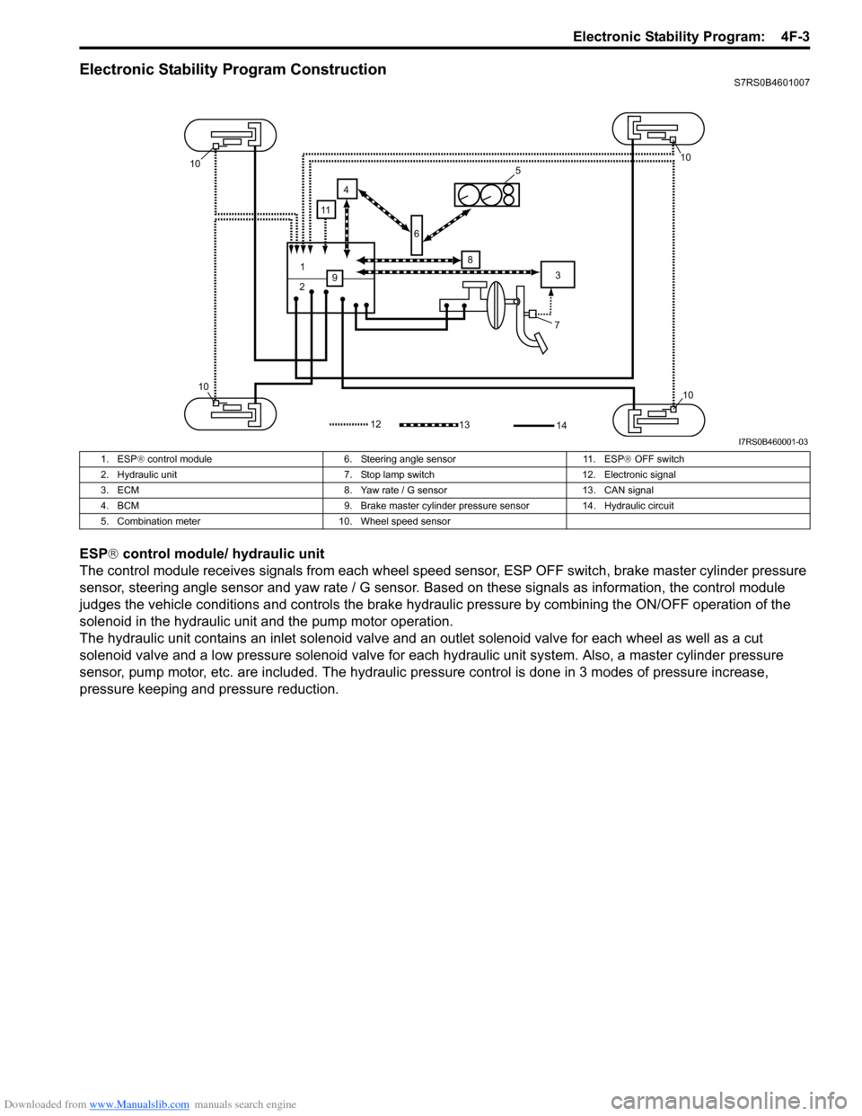
Electronic Stability Program ConstructionS7RS0B4601007
ESP® control module/ hydraulic unit
The control module receives signals from each wheel speed sensor, ESP O FF switch, brake master cylinder pressure
sensor, steering angle sensor and yaw rate / G sensor. Ba sed on these signals as information, the control module
judges the vehicle conditions and controls the brake hydraulic pressure by combining the ON/OFF operation of the
solenoid in the hydraulic unit and the pump motor operation.
The hydraulic unit contains an inlet so lenoid valve and an outlet solenoid valve for each wheel as well as a cut
solenoid valve and a low pressure solenoid valve for each hydraulic unit system. Also, a master cylinder pressure
sensor, pump motor, etc. are included. The hydraulic pre ssure control is done in 3 modes of pressure increase,
pressure keeping and pressure reduction.
7
1
2 3
4
5
6
8
9
10
1010
10
1312
11
14
I7RS0B460001-03
1. ESP ® control module 6. Steering angle sensor 11. ESP ® OFF switch
2. Hydraulic unit 7. Stop lamp switch 12. Electronic signal
3. ECM 8. Yaw rate / G sensor 13. CAN signal
4. BCM 9. Brake master cylinder pre ssure sensor 14. Hydraulic circuit
5. Combination meter 10. Wheel speed sensor
Page 641 of 1496
Downloaded from www.Manualslib.com manuals search engine Table of Contents 5- i
5
Section 5
CONTENTS
Transmission / Transaxle
Precautions ................................................. 5-1
Precautions............................................................. 5-1
Precautions on Transmission / Transaxle ............. 5-1
Automatic Transmission/Transaxle ....... 5A-1
Precautions........................................................... 5A-1Precautions in Diagnosing Trouble ..................... 5A-1
Precautions for Disassembly and Reassembly ...................................................... 5A-1
General Description ............................................. 5A-3 A/T Description ................................................... 5A-3
Clutch / Brake / Planetary Gear Function of Automatic Transaxle ......................................... 5A-6
Table of Component Operation ........................... 5A-7
Brake Interlock System Construction .................. 5A-8
A/T Diagnosis General Description ..................... 5A-8
On-Board Diagnostic System Description ........... 5A-8
CAN Communication System Description........... 5A-9
Schematic and Routing Diagram ...................... 5A-10 Transmission Control Module (TCM) Wiring
Diagram .......................................................... 5A-10
Automatic Gear Shift Table ............................... 5A-12
Component Locatio n ......................................... 5A-13
Electronic Shift Cont rol System Components
Location .......................................................... 5A-13
Diagnostic Information and Procedures .......... 5A-15 A/T System Check ............................................ 5A-15
Visual Inspection ............................................... 5A-18
Malfunction Indicator Lamp (MIL) Check .......... 5A-18
Transmission Warning Ligh t Check .................. 5A-18
DTC Table ......................................................... 5A-19
DTC Check ....................................................... 5A-20
DTC Clearance ................................................. 5A-20
Fail-Safe Table ................ .................................. 5A-21
Scan Tool Data ................................................. 5A-23
A/T Basic Check ............................................... 5A-26
Road Test ......................................................... 5A-27
Manual Road Test ........... .................................. 5A-29
Engine Brake Test ............................................ 5A-30
Stall Test ........................................................... 5A-30
Time Lag Test ................................................... 5A-31
Line Pressure Test .......... .................................. 5A-32
“P” Range Test.................................................. 5A-33
A/T Symptom Diagnosis ..... .............................. 5A-34 No Gear Shift to 4th gear .................................. 5A-41
No Lock-Up Occurs ........................................... 5A-42
Transmission Warning Light Circuit Check –
Light Does Not Come “ON” at Ignition Switch
ON ................................................................... 5A-43
Transmission Warning Light Circuit Check – Light Remains “ON” at Ignition Switch ON ...... 5A-43
DTC P0602: Control Module Programming Error ................................................................ 5A-44
DTC P0705: Transmission Range Sensor Circuit Malfunction (PRNDL input) .................. 5A-44
DTC P0707: Transmission Range Sensor Circuit Low ...................................................... 5A-46
DTC P0712: Transmission Fluid Temperature Sensor “A” Circuit Low ... ................................. 5A-48
DTC P0713: Transmission Fluid Temperature Sensor “A” Circuit High .. ................................. 5A-49
DTC P0717: Input / Turbine Speed Sensor “A” Circuit Malfunction........................................... 5A-51
DTC P0722: Output Speed Sensor Circuit No Signal .............................................................. 5A-52
DTC P0787: Shift / Timing Solenoid Low .......... 5A-54
DTC P0788: Shift / Timing Solenoid High ......... 5A-56
DTC P0961: Pressure Control Solenoid “A”
Control Circuit Range / Performance .............. 5A-58
DTC P0962: Pressure Control Solenoid “A”
Control Circuit Low .......................................... 5A-60
DTC P0963: Pressure Control Solenoid “A”
Control Circuit High ......................................... 5A-62
DTC P0973 / P0976: Shift Solenoid “A” Control Circuit Low / Shift Solenoid “B”
Control Circuit Low .......................................... 5A-64
DTC P0974 / P0977: Shift Solenoid “A” / Shift Solenoid “B” Control Circuit High .................... 5A-66
DTC P1702: Internal Co ntrol Module Memory
Check Sum Error............................................. 5A-68
DTC P1703: Can Invalid Data - TCM ................ 5A-68
DTC P1723: Range Select Switch Malfunction ...................................................... 5A-69
DTC P1774: CAN Communication Bus Off ....... 5A-71
DTC P1777: TCM Lost Communication with ECM (Reception Error).................................... 5A-73
DTC P1778: TCM Lost Communication with BCM (Reception Error).................................... 5A-74