Operating cylinder SUZUKI SWIFT 2008 2.G Service Owner's Manual
[x] Cancel search | Manufacturer: SUZUKI, Model Year: 2008, Model line: SWIFT, Model: SUZUKI SWIFT 2008 2.GPages: 1496, PDF Size: 34.44 MB
Page 859 of 1496

Downloaded from www.Manualslib.com manuals search engine Clutch: 5C-7
Clutch Operating Cylinder Removal and
Installation
S7RS0B5306010
Removal1) Clean around brake master cylinder reservoir cap and take out fluid with syringe or such from brake
master cylinder reservoir.
2) Disconnect clutch fluid pipe (2) from operating cylinder referring to “Clutch Fluid Pipe Removal and
Installation”.
3) Remove clutch operating cylinder (1).
Installation
Reverse removal procedure for installation noting the
following. • Apply grease to push rod tip.
“A”: Grease 99000–25100 (SUZUKI Silicone
Grease)
• Tighten clutch operating cylinder bolt to specified torque.
Tightening torque
Clutch operating cylinder bolt: 23 N·m (2.3 kgf-
m, 17.0 lb-ft)
Clutch Operating Cylinder InspectionS7RS0B5306011
Check operating cylinder for damage and fluid leakage.
If malfunction is found, repl ace clutch operating cylinder.
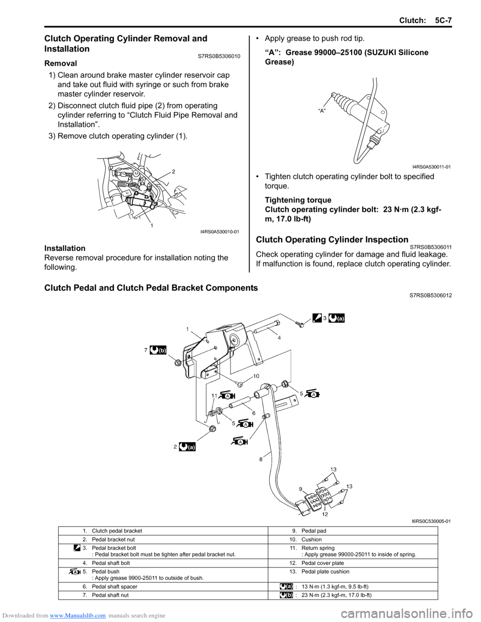
Clutch Pedal and Clutch Pedal Bracket ComponentsS7RS0B5306012
2
1I4RS0A530010-01
“A”
I4RS0A530011-01
I6RS0C530005-01
1. Clutch pedal bracket 9. Pedal pad
2. Pedal bracket nut 10. Cushion
3. Pedal bracket bolt : Pedal bracket bolt must be tighten after pedal bracket nut. 11. Return spring
: Apply grease 99000-25011 to inside of spring.
4. Pedal shaft bolt 12. Pedal cover plate
5. Pedal bush : Apply grease 9900-25011 to outside of bush. 13. Pedal plate cushion
6. Pedal shaft spacer : 13 N⋅m (1.3 kgf-m, 9.5 lb-ft)
7. Pedal shaft nut : 23 N⋅m (2.3 kgf-m, 17.0 lb-ft)
Page 865 of 1496

Downloaded from www.Manualslib.com manuals search engine Clutch: 5C-13
Clutch Release System InspectionS7RS0B5306017
Clutch Release Bearing
Check clutch release bearing for smooth rotation. If
abnormality is found, replace it.
CAUTION!
Do not wash release bearing. Washing may
cause grease leakage and consequential
bearing damage.
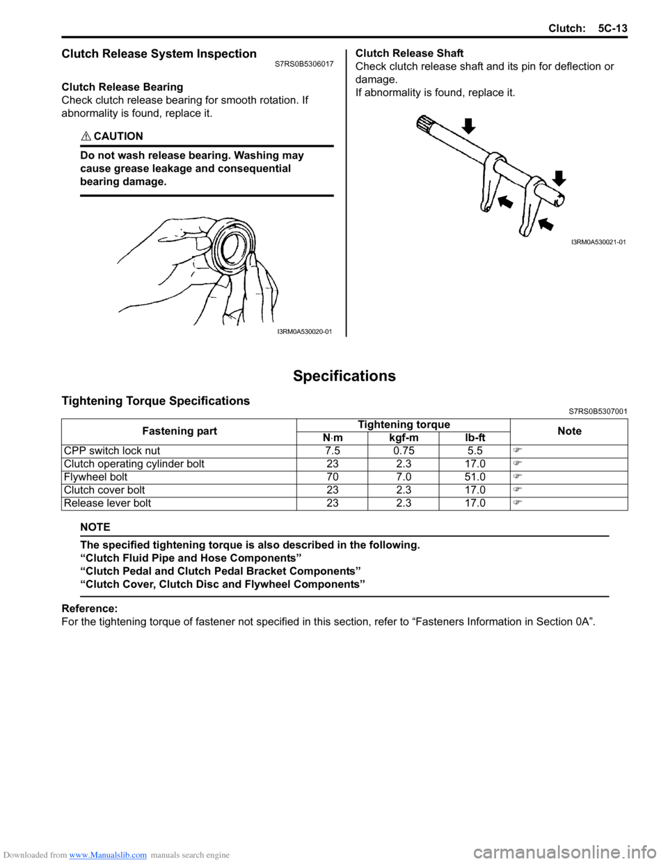
Clutch Release Shaft
Check clutch release shaft and its pin for deflection or
damage.
If abnormality is found, replace it.
Specifications
Tightening Torque SpecificationsS7RS0B5307001
NOTE
The specified tightening torque is also described in the following.
“Clutch Fluid Pipe and Hose Components”
“Clutch Pedal and Clutch Pedal Bracket Components”
“Clutch Cover, Clutch Disc and Flywheel Components”
Reference:
For the tightening torque of fastener not specified in this section, refer to “Fasteners Information in Section 0A”.
I3RM0A530020-01
I3RM0A530021-01
Fastening part Tightening torque
Note
N ⋅mkgf-mlb-ft
CPP switch lock nut 7.5 0.75 5.5 �)
Clutch operating cylinder bolt 23 2.3 17.0 �)
Flywheel bolt 70 7.0 51.0 �)
Clutch cover bolt 23 2.3 17.0 �)
Release lever bolt 23 2.3 17.0 �)
Page 1351 of 1496

Downloaded from www.Manualslib.com manuals search engine Security and Locks: 9F-5
Keyless Entry System Operation InspectionS7RS0B9604004
NOTE
When performing the this inspection, make
sure to have any of the door once opened/
closed after the ignition key has been
removed from the ignition key cylinder.
1) Confirm that power door lock system operates normally, refer to “Power Door Lock System
Operation Inspection”.
2) All doors are closed and unlocked.
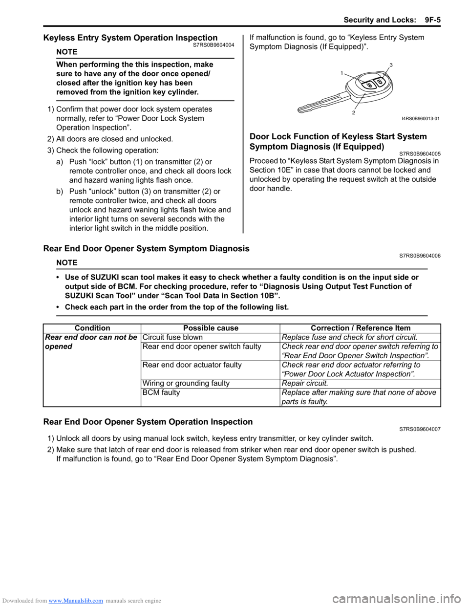
3) Check the following operation: a) Push “lock” button (1 ) on transmitter (2) or
remote controller once, and check all doors lock
and hazard waning lights flash once.
b) Push “unlock” button (3) on transmitter (2) or remote controller twice, and check all doors
unlock and hazard waning lights flash twice and
interior light turns on several seconds with the
interior light switch in the middle position. If malfunction is found, go to “Keyless Entry System
Symptom Diagnosis (If Equipped)”.
Door Lock Function of Keyless Start System
Symptom Diagnosis (If Equipped)
S7RS0B9604005
Proceed to “Keyless Start System Symptom Diagnosis in
Section 10E” in case that doors cannot be locked and
unlocked by operating the request switch at the outside
door handle.
Rear End Door Opener System Symptom DiagnosisS7RS0B9604006
NOTE
• Use of SUZUKI scan tool makes it easy to check wh
ether a faulty condition is on the input side or
output side of BCM. For checking procedure, re fer to “Diagnosis Using Output Test Function of
SUZUKI Scan Tool” under “Scan Tool Data in Section 10B”.
• Check each part in the order from the top of the following list.
Rear End Door Opener System Operation InspectionS7RS0B9604007
1) Unlock all doors by using manu al lock switch, keyless entry transmitter, or key cylinder switch.
2) Make sure that latch of rear end door is released from striker when rear end door opener switch is pushed. If malfunction is found, go to “Rear End Door Opener System Symptom Diagnosis”.
1
3
2I4RS0B960013-01
ConditionPossible cause Correction / Reference Item
Rear end door can not be
opened Circuit fuse blown
Replace fuse and check for short circuit.
Rear end door opener switch faulty Check rear end door opener switch referring to
“Rear End Door Opener Switch Inspection”.
Rear end door actuator faulty Check rear end door actuator referring to
“Power Door Lock Actuator Inspection”.
Wiring or grounding faulty Repair circuit.
BCM faulty Replace after making sure that none of above
parts is faulty.