Release SUZUKI SWIFT 2008 2.G Service Owner's Manual
[x] Cancel search | Manufacturer: SUZUKI, Model Year: 2008, Model line: SWIFT, Model: SUZUKI SWIFT 2008 2.GPages: 1496, PDF Size: 34.44 MB
Page 382 of 1496
Downloaded from www.Manualslib.com manuals search engine 1G-7 Fuel System:
Fuel Pressure Relief ProcedureS7RS0B1706003
CAUTION!
This work must not be done when engine is
hot. If done so, it may cause adverse effect to
catalyst.
NOTE
If ECM detects DTC(s) after servicing, clear
DTC(s) referring to “DTC Clearance in
Section 1A”.
1) Make sure that engine is cold.
2) Shift transaxle gear shift lever in “Neutral” (shift select lever in “P” range for A/T model), set parking
brake and block drive wheels.
3) Remove relay / fuse box cover.
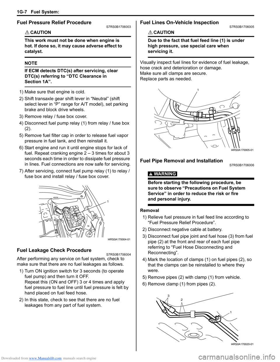
4) Disconnect fuel pump relay (1) from relay / fuse box (2).
5) Remove fuel filter cap in order to release fuel vapor pressure in fuel tank, and then reinstall it.
6) Start engine and run it until engine stops for lack of fuel. Repeat cranking engine 2 – 3 times for about 3
seconds each time in order to dissipate fuel pressure
in lines. Fuel connections are now safe for servicing.
7) After servicing, connect fuel pump relay (1) to relay / fuse box and install re lay / fuse box cover.
Fuel Leakage Check ProcedureS7RS0B1706004
After performing any service on fuel system, check to
make sure that there are no fuel leakages as follows.
1) Turn ON ignition switch for 3 seconds (to operate fuel pump) and then turn it OFF.
Repeat this (ON and OFF) 3 or 4 times and apply
fuel pressure to fuel line until fuel pressure is felt by
hand placed on fuel feed hose.
2) In this state, check to see that there are no fuel leakages from any part of fuel system.
Fuel Lines On-Vehicle InspectionS7RS0B1706005
CAUTION!
Due to the fact that fuel feed line (1) is under
high pressure, use special care when
servicing it.
Visually inspect fuel lines for evidence of fuel leakage,
hose crack and deterioration or damage.
Make sure all cl amps are secure.
Replace parts as needed.
Fuel Pipe Removal and InstallationS7RS0B1706006
WARNING!
Before starting the following procedure, be
sure to observe “Precautions on Fuel System
Service” in order to reduce the risk or fire
and personal injury.
Removal
1) Relieve fuel pressure in fuel feed line according to “Fuel Pressure Relief Procedure”.
2) Disconnect negative cable at battery.
3) Disconnect fuel pipe joint and fuel hose (3) from fuel pipe (2) at the front and rear of each fuel pipe
referring to “Fuel Hose Disconnecting and
Reconnecting”.
4) Mark the location of clamps (1) on fuel pipes (2), so that the clamps can be reinstalled to where they
were.
5) Remove pipes (2) with clamp (1) from vehicle.
6) Remove clamp (1) from pipes (2).
1
I4RS0A170004-01
1
I4RS0A170005-01
2
13
I4RS0A170020-01
Page 401 of 1496
Downloaded from www.Manualslib.com manuals search engine Ignition System: 1H-9
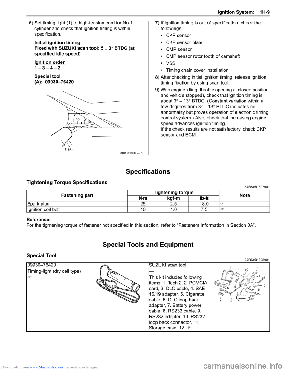
6) Set timing light (1) to high-tension cord for No.1 cylinder and check that ignition timing is within
specification.
Initial ignition timing
Fixed with SUZUKI scan tool: 5 ± 3° BTDC (at
specified idle speed)
Ignition order
1 – 3 – 4 – 2
Special tool
(A): 09930–76420 7) If ignition timing is out
of specification, check the
followings.
• CKP sensor
• CKP sensor plate
• CMP sensor
• CMP sensor rotor tooth of camshaft
• VSS
• Timing chain cover installation
8) After checking initial igniti on timing, release ignition
timing fixation by using scan tool.
9) With engine idling (throttl e opening at closed position
and vehicle stopped), check that ignition timing is
about 3 ° – 13° BTDC. (Constant variation within a
few degrees from 3 ° – 13° BTDC indicates no
abnormality but proves operation of electronic timing
control system.) Also, check that increasing engine
speed advances ignition timing.
If the check results are not satisfactory, check CKP
sensor and ECM.
Specifications
Tightening Torque SpecificationsS7RS0B1807001
Reference:
For the tightening torque of fastener not specified in this section, refer to “Fasteners Information in Section 0A”.
Special Tools and Equipment
Special ToolS7RS0B1808001
1, (A)10
0I3RB0A180004-01
Fastening part Tightening torque
Note
N ⋅mkgf-mlb-ft
Spark plug 25 2.5 18.0 �)
Ignition coil bolt 10 1.0 7.5 �)
09930–76420SUZUKI scan tool
Timing-light (dry cell type) —
�) This kit includes following
items. 1. Tech 2, 2. PCMCIA
card, 3. DLC cable, 4. SAE
16/19 adapter, 5. Cigarette
cable, 6. DLC loop back
adapter, 7. Battery power
cable, 8. RS232 cable, 9.
RS232 adapter, 10. RS232
loop back connector, 11.
Storage case, 12. �)
Page 407 of 1496
Downloaded from www.Manualslib.com manuals search engine Starting System: 1I-6
Starting Motor InspectionS7RS0B1906003
Plunger
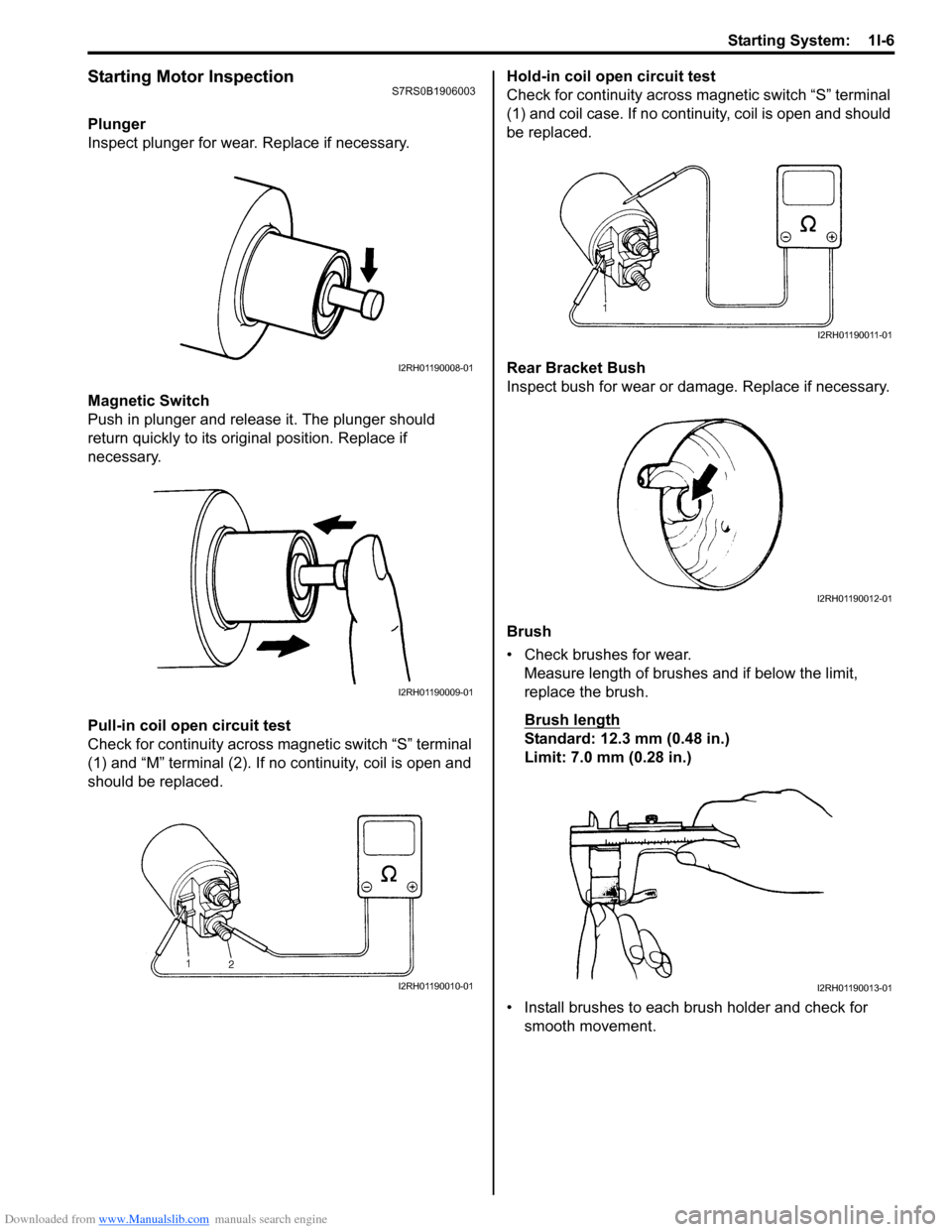
Inspect plunger for wear. Replace if necessary.
Magnetic Switch
Push in plunger and release it. The plunger should
return quickly to its original position. Replace if
necessary.
Pull-in coil open circuit test
Check for continuity across magnetic switch “S” terminal
(1) and “M” terminal (2). If no continuity, coil is open and
should be replaced. Hold-in coil open circuit test
Check for continuity across ma
gnetic switch “S” terminal
(1) and coil case. If no continuity, coil is open and should
be replaced.
Rear Bracket Bush
Inspect bush for wear or damage. Replace if necessary.
Brush
• Check brushes for wear. Measure length of brushes and if below the limit,
replace the brush.
Brush length
Standard: 12.3 mm (0.48 in.)
Limit: 7.0 mm (0.28 in.)
• Install brushes to each brush holder and check for smooth movement.
I2RH01190008-01
I2RH01190009-01
I2RH01190010-01
I2RH01190011-01
I2RH01190012-01
I2RH01190013-01
Page 439 of 1496
Downloaded from www.Manualslib.com manuals search engine Front Suspension: 2B-6
• Tighten wheel nuts to specified torque.
Tightening torque
Wheel nut: 85 N·m (8.5 kgf-m, 61.5 lb-ft)
• After installation, confirm front wheel alignment.
Front Strut Assembly Disassembly and
Assembly
S7RS0B2206004
WARNING!
Use a regular coil spring compressor and
follow the operation procedure described in
the Instruction Manual.
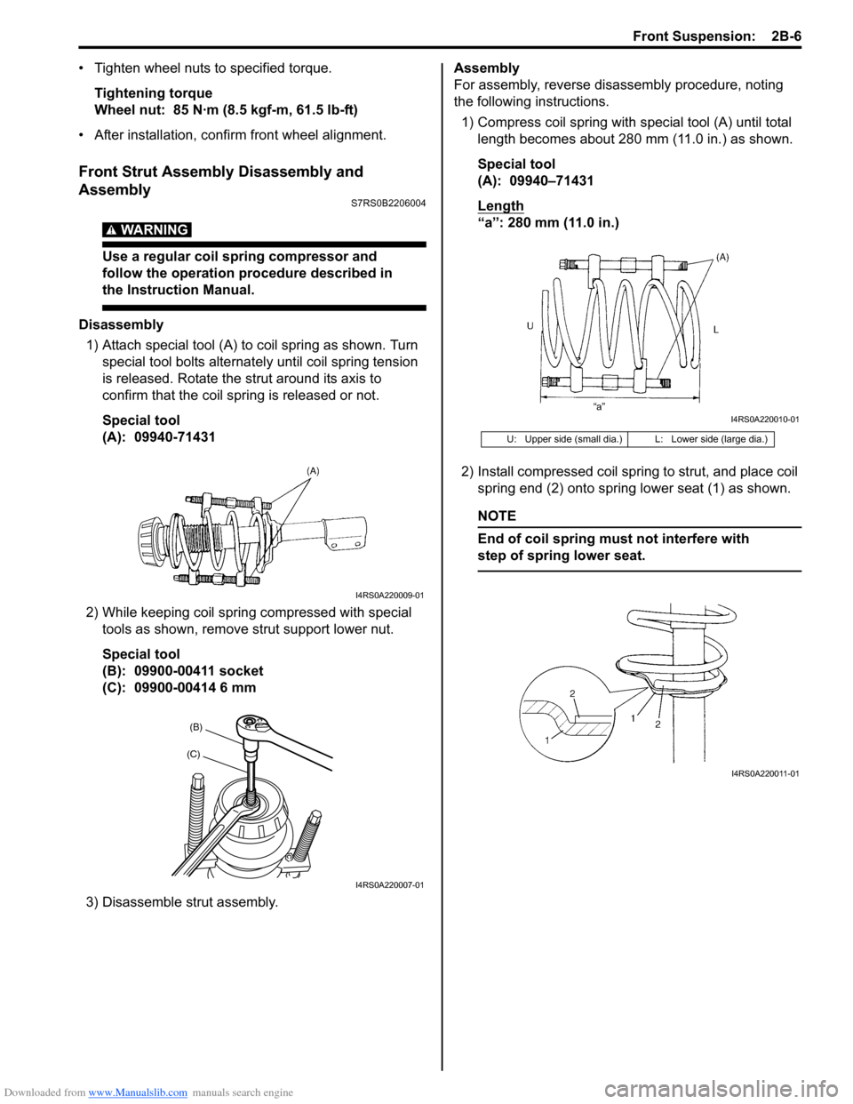
Disassembly 1) Attach special tool (A) to coil spring as shown. Turn special tool bolts alternat ely until coil spring tension
is released. Rotate the strut around its axis to
confirm that the coil spring is released or not.
Special tool
(A): 09940-71431
2) While keeping coil spring compressed with special
tools as shown, remove strut support lower nut.
Special tool
(B): 09900-00411 socket
(C): 09900-00414 6 mm
3) Disassemble strut assembly. Assembly
For assembly, reverse disassembly procedure, noting
the following instructions.
1) Compress coil spring with special tool (A) until total
length becomes about 280 mm (11.0 in.) as shown.
Special tool
(A): 09940–71431
Length
“a”: 280 mm (11.0 in.)
2) Install compressed coil spring to strut, and place coil
spring end (2) onto spring lower seat (1) as shown.
NOTE
End of coil spring must not interfere with
step of spring lower seat.
I4RS0A220009-01
(B)
(C)
I4RS0A220007-01
U: Upper side (small dia.) L: Lower side (large dia.)
I4RS0A220010-01
I4RS0A220011-01
Page 475 of 1496
Downloaded from www.Manualslib.com manuals search engine Wheels and Tires: 2D-8
Tire Mounting and DismountingS7RS0B2406004
CAUTION!
When installing tire which has arrow
indicating tire rotation direction to wheel,
make sure that this tire rotation direction is
same as actual tire rotation direction when
vehicle is moving forward. Otherwise, it is
not possible to install wheel with tire to
vehicle in specified direction.
Use a tire changing machine to mount or dismount tires.
Follow equipment manufacturer’s instructions. Do not
use hand tools or tire irons al one to change tires as they
may damage tire beads or wheel rim.
Rim bead seats should be cleaned with a wire brush or
coarse steel wool to remove lubricants, old rubber and
light rust. Before mounting or dismounting a tire, bead
area should be well lubricated with approved tire
lubricant.
After mounting, inflate to specified pressure shown on
tire placard so that beads are completely seated.
WARNING!
Do not stand over tire when inflating. Bead
may break when bead snaps over rim’s safety
hump and cause serious personal injury.
Do not exceed 330 kpa (47.9 psi) pressure
when inflating. If 330 kpa (47.9 psi) pressure
will not seat beads, deflate, re-lubricate and
reinflate.
Over inflation may cause bead to break and
cause serious personal injury.
Install valve core and inflate to proper pressure.
Tire RepairS7RS0B2406005
There are many different materials and techniques on
the market to repair tires. As not all of these work on all
types of tires, tire manufacturers have published detailed
instructions on how and when to repair tires. These
instructions can be obtained from each tire
manufacturer.
Tire Repair for Emergency Repaired-Tire with
Sealant
S7RS0B2406006
WARNING!
Be sure to observe “Precaution for
Emergency Flat Tire Repair Kit”. Otherwise,
your health may be ruined.
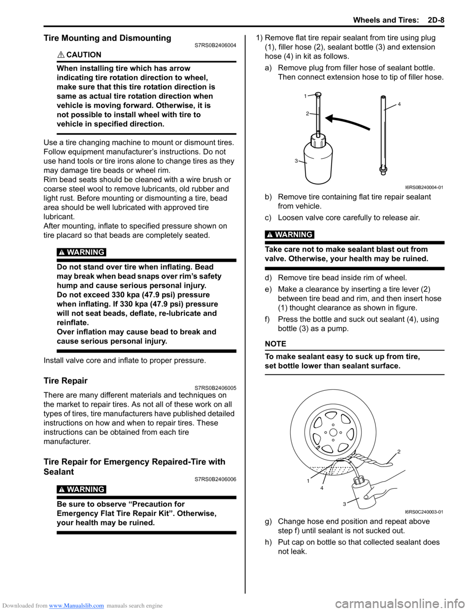
1) Remove flat tire repair sealant from tire using plug (1), filler hose (2), sealant bottle (3) and extension
hose (4) in kit as follows.
a) Remove plug from fille r hose of sealant bottle.
Then connect ext ension hose to tip of filler hose.
b) Remove tire containing flat tire repair sealant from vehicle.
c) Loosen valve core carefully to release air.
WARNING!
Take care not to make sealant blast out from
valve. Otherwise, your health may be ruined.
d) Remove tire bead inside rim of wheel.
e) Make a clearance by inserting a tire lever (2) between tire bead and rim, and then insert hose
(1) thought clearance as shown in figure.
f) Press the bottle and suck out sealant (4), using bottle (3) as a pump.
NOTE
To make sealant easy to suck up from tire,
set bottle lower than sealant surface.
g) Change hose end position and repeat above step f) until sealant is not sucked out.
h) Put cap on bottle so that collected sealant does not leak.
4
1
2
3
I6RS0B240004-01
1 4
3 2
I6RS0C240003-01
Page 483 of 1496
Downloaded from www.Manualslib.com manuals search engine Drive Shaft / Axle: 3A-5
8) Disconnect front suspension control arm ball joint
stud from steering knuckle.
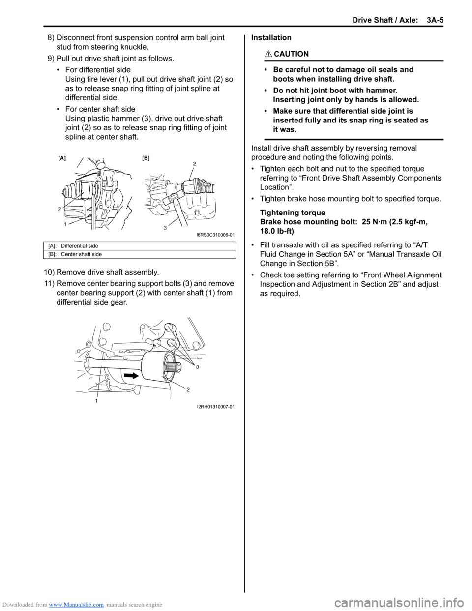
9) Pull out drive shaft joint as follows. • For differential sideUsing tire lever (1), pull out drive shaft joint (2) so
as to release snap ring fitting of joint spline at
differential side.
• For center shaft side Using plastic hammer (3), drive out drive shaft
joint (2) so as to release snap ring fitting of joint
spline at center shaft.
10) Remove drive shaft assembly. 11) Remove center bearing support bolts (3) and remove center bearing support (2) with center shaft (1) from
differential side gear. Installation
CAUTION!
• Be careful not to damage oil seals and
boots when installing drive shaft.
• Do not hit joint boot with hammer. Inserting joint only by hands is allowed.
• Make sure that differential side joint is inserted fully and its snap ring is seated as
it was.
Install drive shaft assemb ly by reversing removal
procedure and noting the following points.
• Tighten each bolt and nut to the specified torque referring to “Front Drive Shaft Assembly Components
Location”.
• Tighten brake hose mounting bolt to specified torque.
Tightening torque
Brake hose mounting bolt: 25 N·m (2.5 kgf-m,
18.0 lb-ft)
• Fill transaxle with oil as sp ecified referring to “A/T
Fluid Change in Section 5A” or “Manual Transaxle Oil
Change in Section 5B”.
• Check toe setting referring to “Front Wheel Alignment Inspection and Adjustment in Section 2B” and adjust
as required.
[A]: Differential side
[B]: Center shaft side
I6RS0C310006-01
3
2
1I2RH01310007-01
Page 503 of 1496
Downloaded from www.Manualslib.com manuals search engine Brake Control System and Diagnosis: 4A-5
If deterioration of rubber is evident, disassemble all
hydraulic parts and wash with alcohol. Dry these parts
with compressed air before assembly to keep alcohol out
of the system. Replace all rubber parts in the system,
including hoses. Also, when working on the brake
mechanisms, check for fluid on the linings.
If excessive fluid is found, replace the pads. If master cylinder piston seals
are satisfactory, check for
leakage or excessive heat co nditions. If leakage is not
found, drain fluid, flush with brake fluid, refill and bleed
system.
The system must be flushed if there is any doubt as to
the grade of fluid in the system or if fluid has been used
which contained parts that have been subjected to
contaminated fluid.
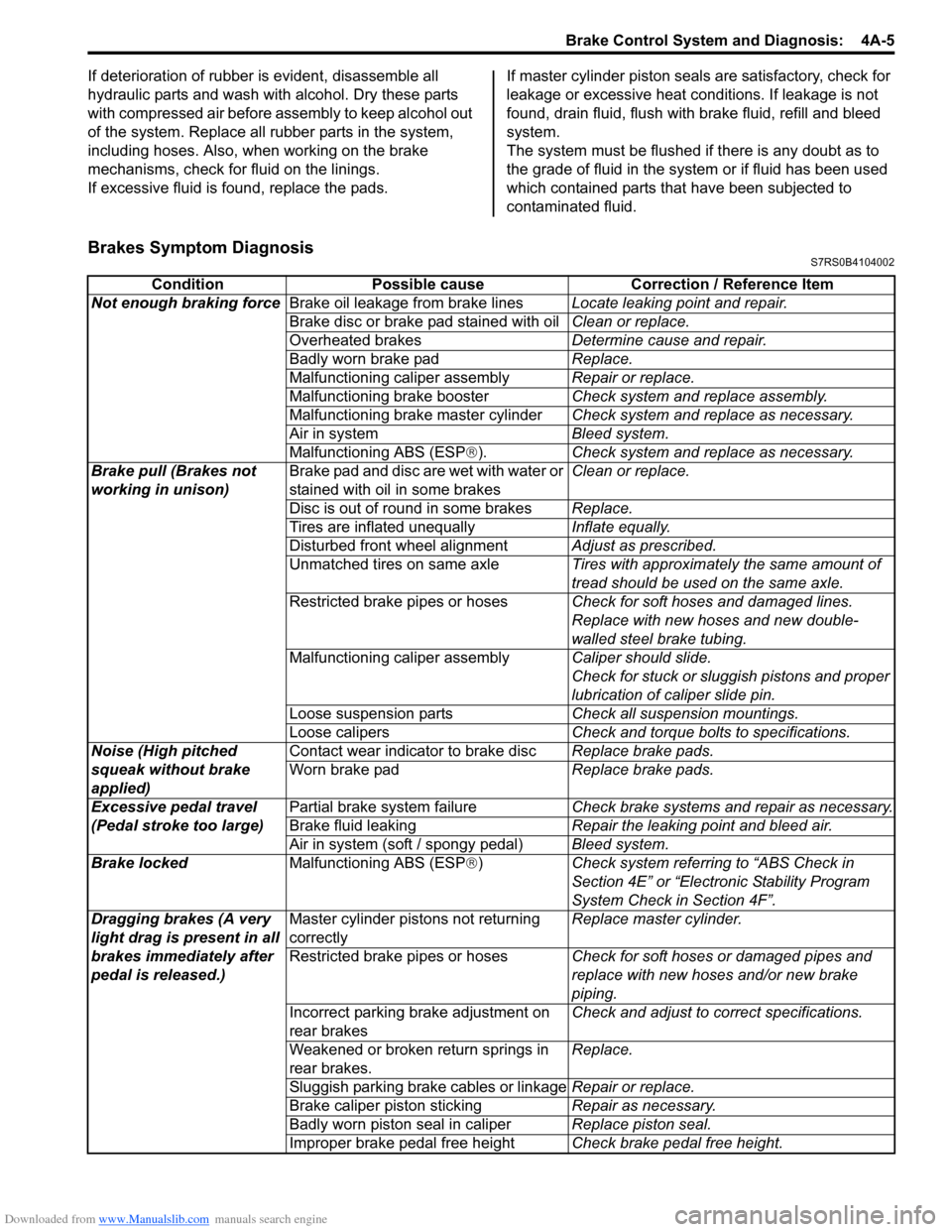
Brakes Symptom DiagnosisS7RS0B4104002
Condition Possible cause Correction / Reference Item
Not enough braking force Brake oil leakage from brake lines Locate leaking point and repair.
Brake disc or brake pad stained with oil Clean or replace.
Overheated brakes Determine cause and repair.
Badly worn brake pad Replace.
Malfunctioning caliper assembly Repair or replace.
Malfunctioning brake booster Check system and replace assembly.
Malfunctioning brake master cylinder Check system and replace as necessary.
Air in system Bleed system.
Malfunctioning ABS (ESP ®). Check system and replace as necessary.
Brake pull (Brakes not
working in unison) Brake pad and disc are wet with water or
stained with oil in some brakes Clean or replace.
Disc is out of round in some brakes Replace.
Tires are inflated unequally Inflate equally.
Disturbed front wheel alignment Adjust as prescribed.
Unmatched tires on same axle Tires with approximately the same amount of
tread should be used on the same axle.
Restricted brake pipes or hoses Check for soft hoses and damaged lines.
Replace with new hoses and new double-
walled steel brake tubing.
Malfunctioning caliper assembly Caliper should slide.
Check for stuck or sluggish pistons and proper
lubrication of caliper slide pin.
Loose suspension parts Check all suspension mountings.
Loose calipers Check and torque bolts to specifications.
Noise (High pitched
squeak without brake
applied) Contact wear indicator to brake disc
Replace brake pads.
Worn brake pad Replace brake pads.
Excessive pedal travel
(Pedal stroke too large) Partial brake system failure
Check brake systems and repair as necessary.
Brake fluid leaking Repair the leaking point and bleed air.
Air in system (soft / spongy pedal) Bleed system.
Brake locked Malfunctioning ABS (ESP®) Check system referri ng to “ABS Check in
Section 4E” or “Electronic Stability Program
System Check in Section 4F”.
Dragging brakes (A very
light drag is present in all
brakes immediately after
pedal is released.) Master cylinder pistons not returning
correctly
Replace master cylinder.
Restricted brake pipes or hoses Check for soft hoses or damaged pipes and
replace with new hoses and/or new brake
piping.
Incorrect parking brake adjustment on
rear brakes Check and adjust to correct specifications.
Weakened or broken return springs in
rear brakes. Replace.
Sluggish parking brake cables or linkage Repair or replace.
Brake caliper piston sticking Repair as necessary.
Badly worn piston seal in caliper Replace piston seal.
Improper brake pedal free height Check brake pedal free height.
Page 504 of 1496
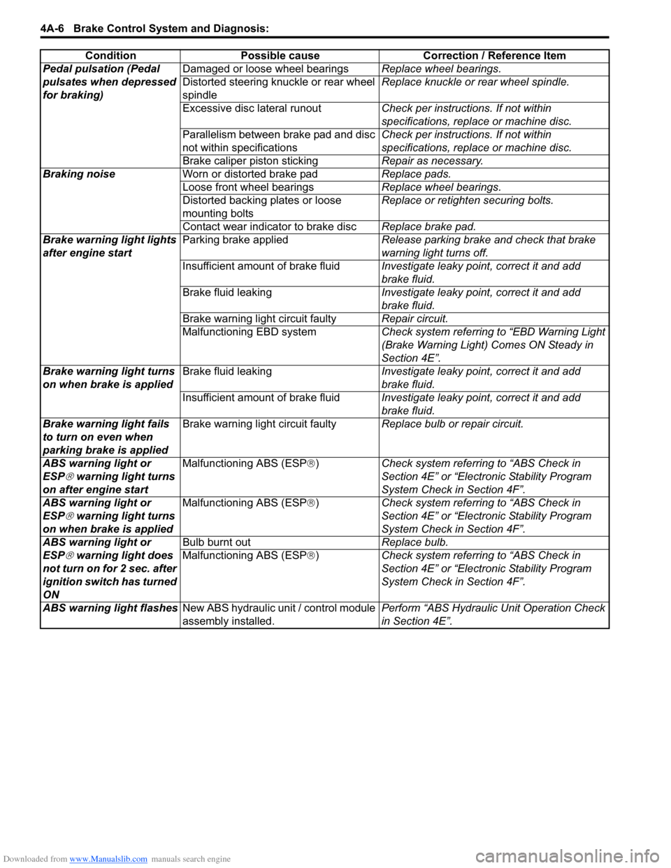
Downloaded from www.Manualslib.com manuals search engine 4A-6 Brake Control System and Diagnosis:
Pedal pulsation (Pedal
pulsates when depressed
for braking)Damaged or loose wheel bearings
Replace wheel bearings.
Distorted steering knuckle or rear wheel
spindle Replace knuckle or rear wheel spindle.
Excessive disc lateral runout Check per instructions. If not within
specifications, replace or machine disc.
Parallelism between brake pad and disc
not within specifications Check per instructions. If not within
specifications, replace or machine disc.
Brake caliper piston sticking Repair as necessary.
Braking noise Worn or distorted brake pad Replace pads.
Loose front wheel bearings Replace wheel bearings.
Distorted backing plates or loose
mounting bolts Replace or retighten securing bolts.
Contact wear indicator to brake disc Replace brake pad.
Brake warning light lights
after engine start Parking brake applied
Release parking brake and check that brake
warning light turns off.
Insufficient amount of brake fluid Investigate leaky point, correct it and add
brake fluid.
Brake fluid leaking Investigate leaky point, correct it and add
brake fluid.
Brake warning light circuit faulty Repair circuit.
Malfunctioning EBD system Check system referring to “EBD Warning Light
(Brake Warning Light) Comes ON Steady in
Section 4E”.
Brake warning light turns
on when brake is applied Brake fluid leaking
Investigate leaky point, correct it and add
brake fluid.
Insufficient amount of brake fluid Investigate leaky point, correct it and add
brake fluid.
Brake warning light fails
to turn on even when
parking brake is applied Brake warning light circuit faulty
Replace bulb or repair circuit.
ABS warning light or
ESP
® warning light turns
on after engine start Malfunctioning ABS (ESP
®) Check system referri ng to “ABS Check in
Section 4E” or “Electronic Stability Program
System Check in Section 4F”.
ABS warning light or
ESP
® warning light turns
on when brake is applied Malfunctioning ABS (ESP
®) Check system referri ng to “ABS Check in
Section 4E” or “Electronic Stability Program
System Check in Section 4F”.
ABS warning light or
ESP
® warning light does
not turn on for 2 sec. after
ignition switch has turned
ON Bulb burnt out
Replace bulb.
Malfunctioning ABS (ESP ®) Check system referri ng to “ABS Check in
Section 4E” or “Electronic Stability Program
System Check in Section 4F”.
ABS warning light flashes New ABS hydraulic unit / control module
assembly installed. Perform “ABS Hydraulic
Unit Operation Check
in Section 4E”.
Condition Possible cause Correction / Reference Item
Page 526 of 1496
Downloaded from www.Manualslib.com manuals search engine 4C-2 Rear Brakes:
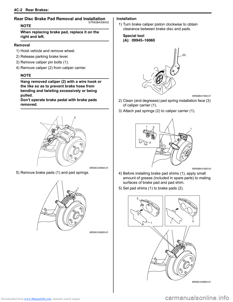
Rear Disc Brake Pad Removal and InstallationS7RS0B4306002
NOTE
When replacing brake pad, replace it on the
right and left.
Removal1) Hoist vehicle and remove wheel.
2) Release parking brake lever.
3) Remove caliper pin bolts (1).
4) Remove caliper (2) from caliper carrier.
NOTE
Hang removed caliper (2) with a wire hook or
the like so as to prevent brake hose from
bending and twisting excessively or being
pulled.
Don’t operate brake pedal with brake pads
removed.
5) Remove brake pads (1) and pad springs. Installation
1) Turn brake caliper piston clockwise to obtain clearance between brake disc and pads.
Special tool
(A): 09945–16060
2) Clean (and degrease) pad spring installation face (3) of caliper carrier (1).
3) Attach pad springs (2) to caliper carrier (1).
4) Before installing brake p ad shims (1), apply small
amount of grease (included in spare parts) to mating
surfaces of brake pad and pad shim.
5) Set pad shims (1) to brake pads (2).
1 2
I6RS0C430002-01
1
I6RS0C430003-01
(A)
I6RS0B431004-01
113
2
I6RS0B431005-03
2
1
1 2
I6RS0C430004-01
Page 527 of 1496
Downloaded from www.Manualslib.com manuals search engine Rear Brakes: 4C-3
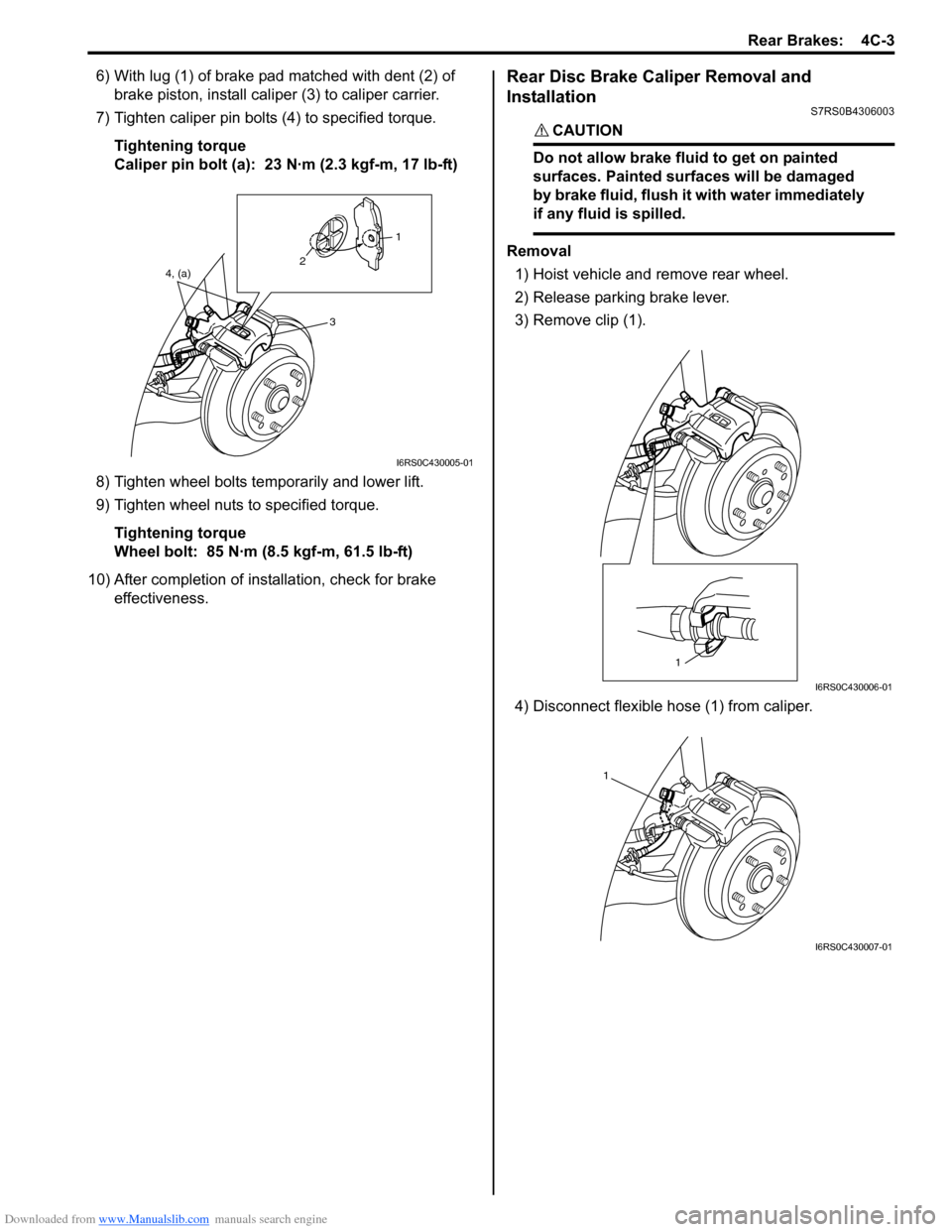
6) With lug (1) of brake pad matched with dent (2) of brake piston, install caliper (3) to caliper carrier.
7) Tighten caliper pin bolts (4) to specified torque.
Tightening torque
Caliper pin bolt (a): 23 N·m (2.3 kgf-m, 17 lb-ft)
8) Tighten wheel bolts temporarily and lower lift.
9) Tighten wheel nuts to specified torque. Tightening torque
Wheel bolt: 85 N·m (8.5 kgf-m, 61.5 lb-ft)
10) After completion of installation, check for brake effectiveness.Rear Disc Brake Caliper Removal and
Installation
S7RS0B4306003
CAUTION!
Do not allow brake fluid to get on painted
surfaces. Painted surfaces will be damaged
by brake fluid, flush it with water immediately
if any fluid is spilled.
Removal
1) Hoist vehicle and remove rear wheel.
2) Release parking brake lever.
3) Remove clip (1).
4) Disconnect flexible hose (1) from caliper.
4, (a) 21
3
I6RS0C430005-01
1
I6RS0C430006-01
1
I6RS0C430007-01