Reverse SUZUKI SWIFT 2008 2.G Service Owner's Manual
[x] Cancel search | Manufacturer: SUZUKI, Model Year: 2008, Model line: SWIFT, Model: SUZUKI SWIFT 2008 2.GPages: 1496, PDF Size: 34.44 MB
Page 419 of 1496
Downloaded from www.Manualslib.com manuals search engine Charging System: 1J-9
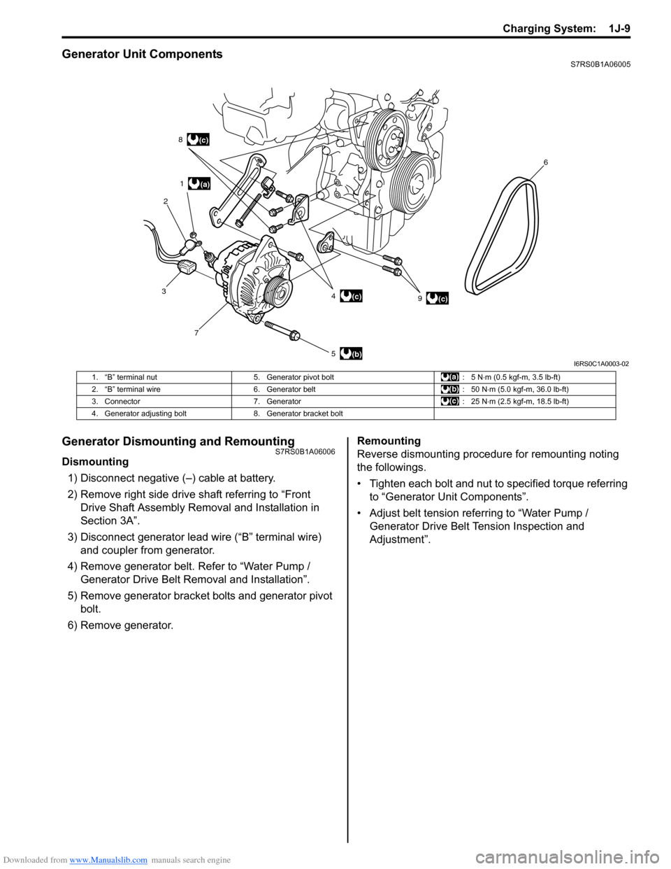
Generator Unit ComponentsS7RS0B1A06005
Generator Dismounting and RemountingS7RS0B1A06006
Dismounting1) Disconnect negative (–) cable at battery.
2) Remove right side drive shaft referring to “Front Drive Shaft Assembly Removal and Installation in
Section 3A”.
3) Disconnect generator lead wire (“B” terminal wire) and coupler from generator.
4) Remove generator belt. Refer to “Water Pump / Generator Drive Belt Re moval and Installation”.
5) Remove generator bracket bolts and generator pivot bolt.
6) Remove generator. Remounting
Reverse dismounting procedure for remounting noting
the followings.
• Tighten each bolt and nut to specified torque referring
to “Generator Unit Components”.
• Adjust belt tension referring to “Water Pump / Generator Drive Belt Tension Inspection and
Adjustment”.
(a)
(b)
(c)
1
2 8
3 7 5 49 6(c)
(c)
I6RS0C1A0003-02
1. “B” terminal nut
5. Generator pivot bolt : 5 N⋅m (0.5 kgf-m, 3.5 lb-ft)
2. “B” terminal wire 6. Generator belt : 50 N⋅m (5.0 kgf-m, 36.0 lb-ft)
3. Connector 7. Generator : 25 N⋅m (2.5 kgf-m, 18.5 lb-ft)
4. Generator adjusting bolt 8. Generator bracket bolt
Page 439 of 1496
Downloaded from www.Manualslib.com manuals search engine Front Suspension: 2B-6
• Tighten wheel nuts to specified torque.
Tightening torque
Wheel nut: 85 N·m (8.5 kgf-m, 61.5 lb-ft)
• After installation, confirm front wheel alignment.
Front Strut Assembly Disassembly and
Assembly
S7RS0B2206004
WARNING!
Use a regular coil spring compressor and
follow the operation procedure described in
the Instruction Manual.
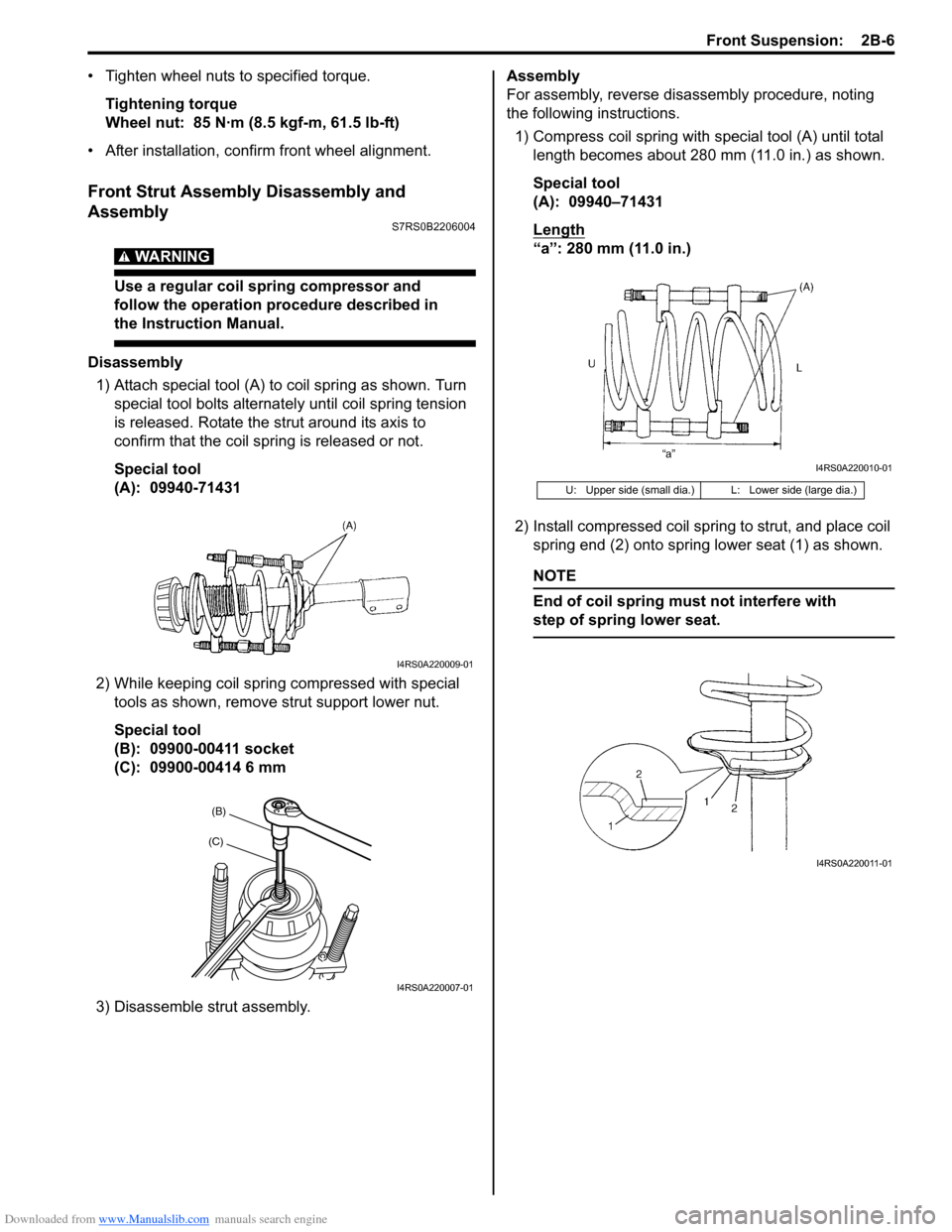
Disassembly 1) Attach special tool (A) to coil spring as shown. Turn special tool bolts alternat ely until coil spring tension
is released. Rotate the strut around its axis to
confirm that the coil spring is released or not.
Special tool
(A): 09940-71431
2) While keeping coil spring compressed with special
tools as shown, remove strut support lower nut.
Special tool
(B): 09900-00411 socket
(C): 09900-00414 6 mm
3) Disassemble strut assembly. Assembly
For assembly, reverse disassembly procedure, noting
the following instructions.
1) Compress coil spring with special tool (A) until total
length becomes about 280 mm (11.0 in.) as shown.
Special tool
(A): 09940–71431
Length
“a”: 280 mm (11.0 in.)
2) Install compressed coil spring to strut, and place coil
spring end (2) onto spring lower seat (1) as shown.
NOTE
End of coil spring must not interfere with
step of spring lower seat.
I4RS0A220009-01
(B)
(C)
I4RS0A220007-01
U: Upper side (small dia.) L: Lower side (large dia.)
I4RS0A220010-01
I4RS0A220011-01
Page 442 of 1496
Downloaded from www.Manualslib.com manuals search engine 2B-9 Front Suspension:
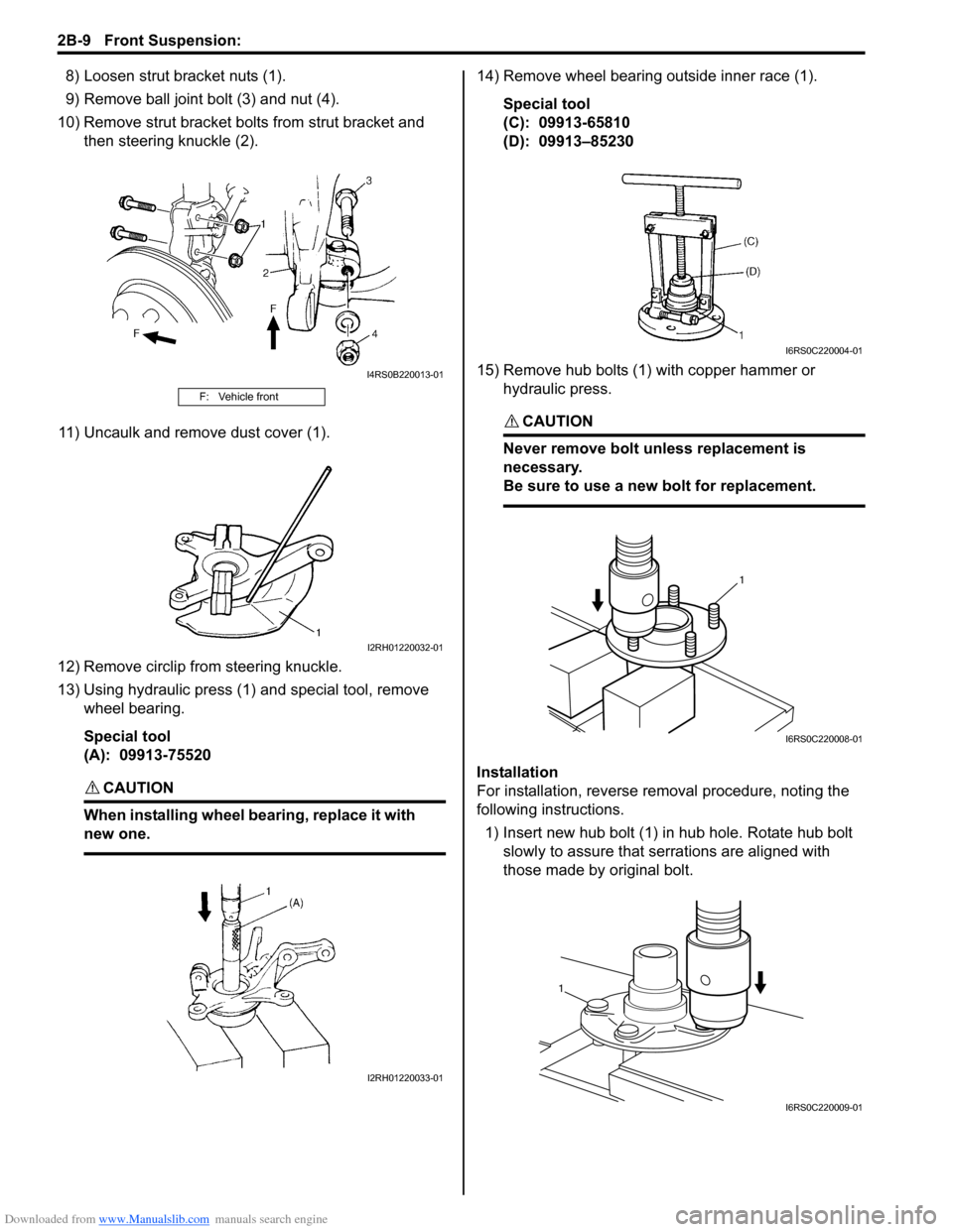
8) Loosen strut bracket nuts (1).
9) Remove ball joint bolt (3) and nut (4).
10) Remove strut bracket bolt s from strut bracket and
then steering knuckle (2).
11) Uncaulk and remove dust cover (1).
12) Remove circlip from steering knuckle.
13) Using hydraulic press (1) and special tool, remove wheel bearing.
Special tool
(A): 09913-75520
CAUTION!
When installing wheel bearing, replace it with
new one.
14) Remove wheel bearing outside inner race (1).
Special tool
(C): 09913-65810
(D): 09913–85230
15) Remove hub bolts (1) with copper hammer or hydraulic press.
CAUTION!
Never remove bolt unle ss replacement is
necessary.
Be sure to use a new bolt for replacement.
Installation
For installation, reverse removal procedure, noting the
following instructions.
1) Insert new hub bolt (1) in hub hole. Rotate hub bolt slowly to assure that serrations are aligned with
those made by original bolt.
F: Vehicle front
I4RS0B220013-01
I2RH01220032-01
I2RH01220033-01
I6RS0C220004-01
1
I6RS0C220008-01
1
I6RS0C220009-01
Page 471 of 1496
Downloaded from www.Manualslib.com manuals search engine Wheels and Tires: 2D-4
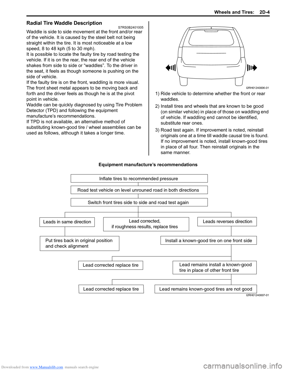
Radial Tire Waddle DescriptionS7RS0B2401005
Waddle is side to side movement at the front and/or rear
of the vehicle. It is caused by the steel belt not being
straight within the tire. It is most noticeable at a low
speed, 8 to 48 kph (5 to 30 mph).
It is possible to locate the f aulty tire by road testing the
vehicle. If it is on the rear , the rear end of the vehicle
shakes from side to side or “waddles”. To the driver in
the seat, it feels as though someone is pushing on the
side of vehicle.
If the faulty tire is on the front, waddling is more visual.
The front sheet metal appears to be moving back and
forth and the driver feels as though he is at the pivot
point in vehicle.
Waddle can be quickly diagnosed by using Tire Problem
Detector (TPD) and following the equipment
manufacture’s recommendations.
If TPD is not available, an alternative method of
substituting known-good tire / wheel assemblies can be
used as follows, although it takes a longer time. 1) Ride vehicle to determine whether the front or rear
waddles.
2) Install tires and wheels that are known to be good (on similar vehicle) in place of those on waddling end
of vehicle. If waddling end cannot be identified,
substitute rear ones.
3) Road test again. If improvement is noted, reinstall originals one at a time till w addle causal tire is found.
If no improvement is noted, install known-good tires
in place of all four. Then reinstall originals in the
same manner.
Equipment manufacture’s recommendations
I2RH01240006-01
Inflate tires to recommended pressure
Road test vehicle on level unrouned road in both directions
Switch front tires side to side and road test again
Lead corrected,
if roughness results, replace tiresLeads in same directionLeads reverses direction
Put tires back in original position
and check alignmentInstall a known-good tire on one front side
Lead remains install a known-good
tire in place of other front tire
Lead remains known-good tires are not goodLead corrected replace tire
Lead corrected replace tire
I2RH01240007-01
Page 474 of 1496
Downloaded from www.Manualslib.com manuals search engine 2D-7 Wheels and Tires:
Wheel Removal and InstallationS7RS0B2406003
Removal
WARNING!
Do not removal all of the wheel nuts at once,
because all the wheels of this vehicle are
mounted by the wheel nuts.
Leave a nut at least not to drop the wheel.
Support the wheel and/or tire and then
remove the nut(s) left with the wheel.
1) Loosen wheel nuts by approximately 180° (half a
rotation).
2) Hoist vehicle.
3) Make sure that the vehicle will not fall off by trying to
move vehicle body in both ways.
4) Remove wheel nut except one.
5) Support the wheel and/or tire not to drop the wheel and then remove the nut left with the wheel.
CAUTION!
Never use heat to loosen tight wheel because
the application of heat to wheel causes the
wheel life shorter and the wheel bearing
damage.
Installation
CAUTION!
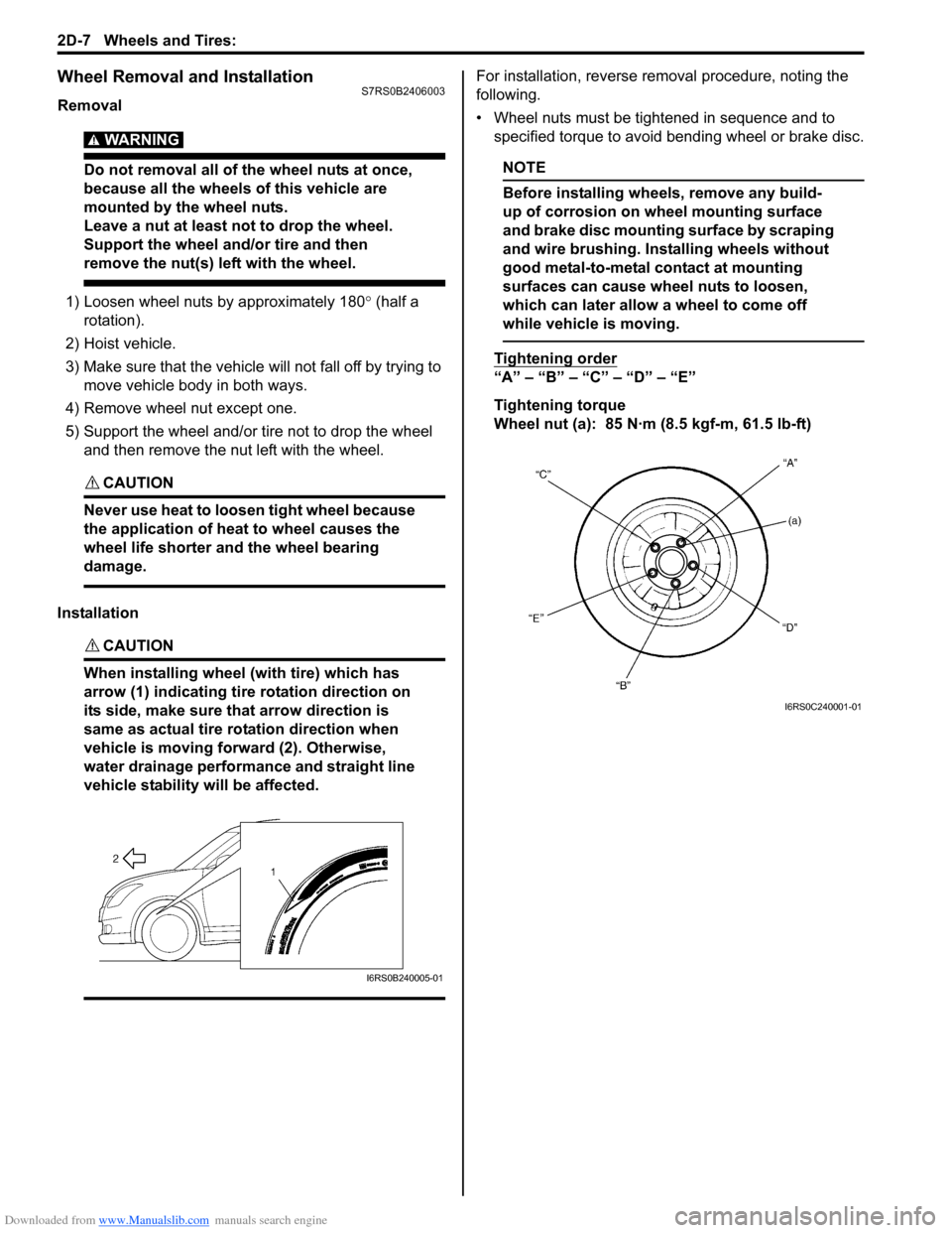
When installing wheel (with tire) which has
arrow (1) indicating tire rotation direction on
its side, make sure that arrow direction is
same as actual tire ro tation direction when
vehicle is moving forw ard (2). Otherwise,
water drainage performance and straight line
vehicle stability will be affected.
For installation, reverse removal procedure, noting the
following.
• Wheel nuts must be tightened in sequence and to specified torque to avoid bending wheel or brake disc.
NOTE
Before installing wheels, remove any build-
up of corrosion on wheel mounting surface
and brake disc mounting surface by scraping
and wire brushing. Installing wheels without
good metal-to-metal contact at mounting
surfaces can cause wheel nuts to loosen,
which can later allow a wheel to come off
while vehicle is moving.
Tightening order
“A” – “B” – “C” – “D” – “E”
Tightening torque
Wheel nut (a): 85 N·m (8.5 kgf-m, 61.5 lb-ft)
I6RS0B240005-01
I6RS0C240001-01
Page 508 of 1496
Downloaded from www.Manualslib.com manuals search engine 4A-10 Brake Control System and Diagnosis:
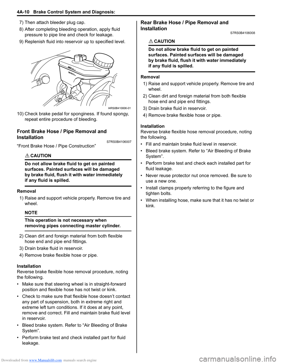
7) Then attach bleeder plug cap.
8) After completing bleeding operation, apply fluid pressure to pipe line and check for leakage.
9) Replenish fluid into reserv oir up to specified level.
10) Check brake pedal for sponginess. If found spongy, repeat entire procedure of bleeding.
Front Brake Hose / Pipe Removal and
Installation
S7RS0B4106007
“Front Brake Hose / Pipe Construction”
CAUTION!
Do not allow brake fluid to get on painted
surfaces. Painted surfaces will be damaged
by brake fluid, flush it with water immediately
if any fluid is spilled.
Removal
1) Raise and support vehicle properly. Remove tire and wheel.
NOTE
This operation is not necessary when
removing pipes connecting master cylinder.
2) Clean dirt and foreign mate rial from both flexible
hose end and pipe end fittings.
3) Drain brake fluid in reservoir.
4) Remove brake flexible hose or pipe.
Installation
Reverse brake flexible hose removal procedure, noting
the following.
• Make sure that steering wh eel is in straight-forward
position and flexible hose has not twist or kink.
• Check to make sure that flexible hose doesn’t contact any part of suspension, both in extreme right and
extreme left turn conditions. If it does at any point,
remove and correct. Fill and maintain brake fluid level
in reservoir.
• Bleed brake system. Refer to “Air Bleeding of Brake System”.
• Perform brake test and check installed part for fluid leakage.
Rear Brake Hose / Pipe Removal and
Installation
S7RS0B4106008
CAUTION!
Do not allow brake fluid to get on painted
surfaces. Painted surfaces will be damaged
by brake fluid, flush it with water immediately
if any fluid is spilled.
Removal
1) Raise and support vehicle properly. Remove tire and wheel.
2) Clean dirt and foreign material from both flexible hose end and pipe end fittings.
3) Drain brake fluid in reservoir.
4) Remove brake flexible hose or pipe.
Installation
Reverse brake flexible hose removal procedure, noting
the following.
• Fill and maintain brake fluid level in reservoir.
• Bleed brake system. Refer to “Air Bleeding of Brake System”.
• Perform brake test and check each installed part for fluid leakage.
• Never reuse protector nut once removed. Be sure to use a new one.
• Install clamps properly referring to the figure and tighten bolts.
• When installing hose, make sure that it has no twist or
kink.
I4RS0B410006-01
Page 521 of 1496
Downloaded from www.Manualslib.com manuals search engine Front Brakes: 4B-5
Assembly
Assemble parts in reverse order of disassembly,
observing the following instructions.
CAUTION!
• Wash each part cleanly before installation in the same fluid as the one used in master
cylinder reservoir.
• Never use other fluid or thinner.
• Before installing piston seal or cylinder boot to cylinder, apply brake fluid to them.
• Install a new piston seal into groove in cylinder securely making sure that it is not
twisted.
• Before installing caliper to carrier, check for slid pin smooth movement in thrust
direction.
• After reassembling brake lines, bleed air from them.
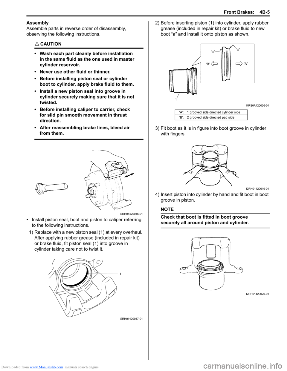
• Install piston seal, boot and piston to caliper referring to the following instructions.
1) Replace with a new piston seal (1) at every overhaul. After applying rubber grease (included in repair kit)
or brake fluid, fit piston seal (1) into groove in
cylinder taking care not to twist it. 2) Before inserting piston (1) into cylinder, apply rubber
grease (included in repair kit) or brake fluid to new
boot “a” and install it onto piston as shown.
3) Fit boot as it is in figure into boot groove in cylinder with fingers.
4) Insert piston into cylinder by hand and fit boot in boot groove in piston.
NOTE
Check that boot is fitted in boot groove
securely all around piston and cylinder.
I2RH01420016-01
1
I2RH01420017-01
“A”: 1 grooved side directed cylinder side
“B”: 2 grooved side directed pad side
I4RS0A420006-01
I2RH01420019-01
I2RH01420020-01
Page 532 of 1496
Downloaded from www.Manualslib.com manuals search engine 4C-8 Rear Brakes:
Rear Disc Brake Caliper InspectionS7RS0B4306006
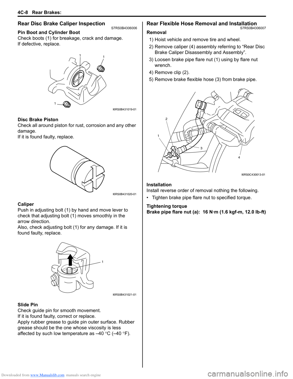
Pin Boot and Cylinder Boot
Check boots (1) for breakage, crack and damage.
If defective, replace.
Disc Brake Piston
Check all around piston for rust, corrosion and any other
damage.
If it is found faulty, replace.
Caliper
Push in adjusting bolt (1) by hand and move lever to
check that adjusting bolt (1) moves smoothly in the
arrow direction.
Also, check adjusting bolt (1) for any damage. If it is
found faulty, replace.
Slide Pin
Check guide pin for smooth movement.
If it is found faulty, correct or replace.
Apply rubber grease to guide pin outer surface. Rubber
grease should be the one whose viscosity is less
affected by such low temperature as –40 °C (–40 ° F).
Rear Flexible Hose Removal and InstallationS7RS0B4306007
Removal
1) Hoist vehicle and remove tire and wheel.
2) Remove caliper (4) assembly referring to “Rear Disc Brake Caliper Disassembly and Assembly”.
3) Loosen brake pipe flare nut (1) using by flare nut wrench.
4) Remove clip (2).
5) Remove brake flexible hose (3) from brake pipe.
Installation
Install reverse order of removal nothing the following.
• Tighten brake pipe flare nut to specified torque.
Tightening torque
Brake pipe flare nut (a): 16 N·m (1.6 kgf-m, 12.0 lb-ft)
1 1
1
I6RS0B431019-01
I6RS0B431020-01
1
I6RS0B431021-01
1
2
3
4
I6RS0C430013-01
Page 533 of 1496
Downloaded from www.Manualslib.com manuals search engine Rear Brakes: 4C-9
Rear Brake Disc Removal and InstallationS7RS0B4306008
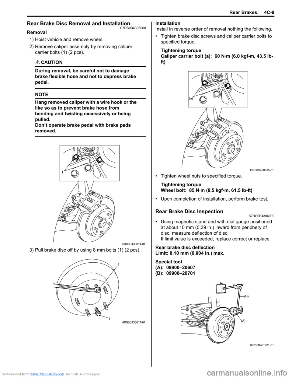
Removal1) Hoist vehicle and remove wheel.
2) Remove caliper assembly by removing caliper
carrier bolts (1) (2 pcs).
CAUTION!
During removal, be ca reful not to damage
brake flexible hose and not to depress brake
pedal.
NOTE
Hang removed caliper with a wire hook or the
like so as to prevent brake hose from
bending and twisting excessively or being
pulled.
Don’t operate brake pedal with brake pads
removed.
3) Pull brake disc off by using 8 mm bolts (1) (2 pcs). Installation
Install in reverse order of removal nothing the following.
• Tighten brake disc screws and caliper carrier bolts to
specified torque.
Tightening torque
Caliper carrier bolt (a): 60 N·m (6.0 kgf-m, 43.5 lb-
ft)
• Tighten wheel nuts to specified torque. Tightening torque
Wheel bolt: 85 N·m (8.5 kgf-m, 61.5 lb-ft)
• Upon completion of installation, perform brake test.
Rear Brake Disc InspectionS7RS0B4306009
• Using magnetic stand and with dial gauge positioned at about 10 mm (0.39 in.) inward from periphery of
disc, measure deflection of disc.
If limit value is exceeded, replace correct or replace.
Rear brake disc deflection
Limit: 0.10 mm (0.004 in.) max.
Special tool
(A): 09900–20607
(B): 09900–20701
1
I6RS0C430014-01
1 1I6RS0C430017-01
(a)
I6RS0C430015-01
(B)
(A)
I6RS0B431031-01
Page 539 of 1496
Downloaded from www.Manualslib.com manuals search engine Parking Brake: 4D-4
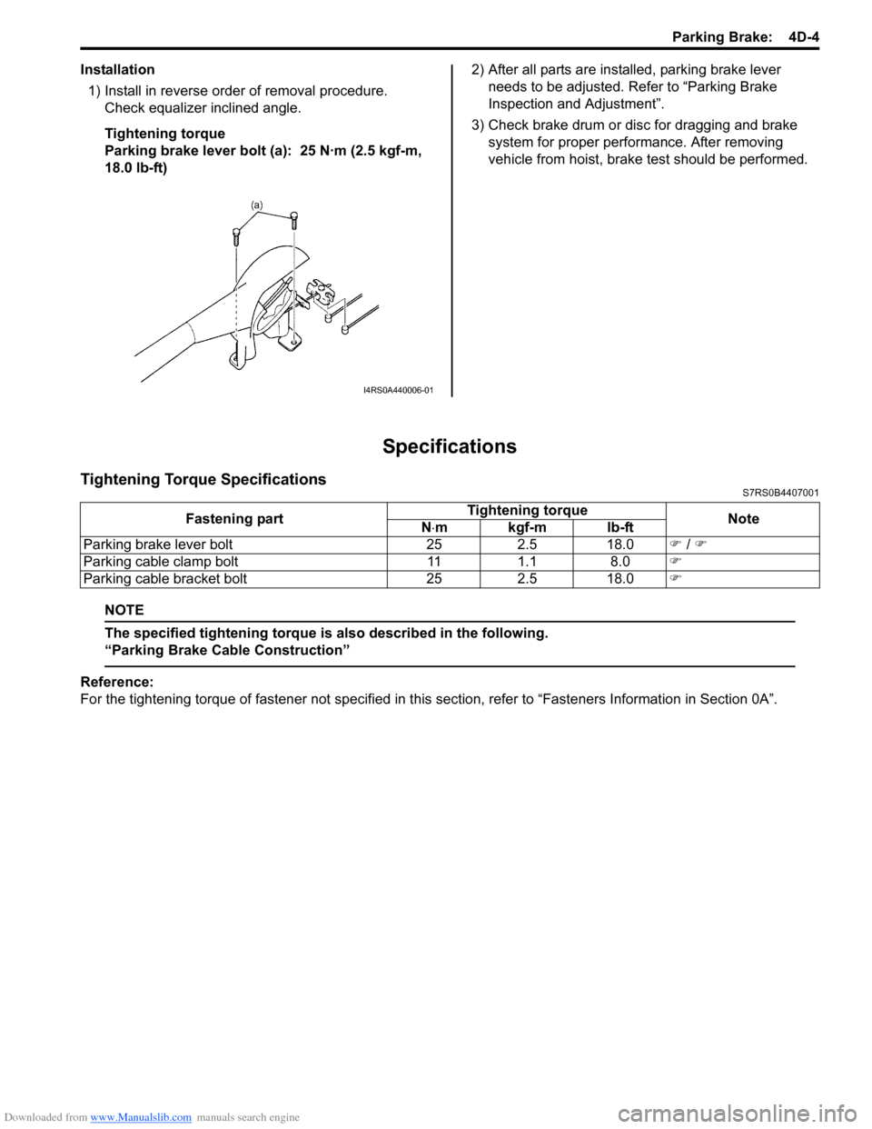
Installation1) Install in reverse order of removal procedure. Check equalizer inclined angle.
Tightening torque
Parking brake lever bolt (a): 25 N·m (2.5 kgf-m,
18.0 lb-ft) 2) After all parts are installed, parking brake lever
needs to be adjusted. Refer to “Parking Brake
Inspection and Adjustment”.
3) Check brake drum or disc for dragging and brake system for proper performance. After removing
vehicle from hoist, brake test should be performed.
Specifications
Tightening Torque SpecificationsS7RS0B4407001
NOTE
The specified tightening torque is also described in the following.
“Parking Brake Cable Construction”
Reference:
For the tightening torque of fastener not specified in this section, refer to “Fasteners Information in Section 0A”.
I4RS0A440006-01
Fastening part Tightening torque
Note
N ⋅mkgf-mlb-ft
Parking brake lever bolt 25 2.5 18.0 �) / �)
Parking cable clamp bolt 11 1.1 8.0 �)
Parking cable bracket bolt 25 2.5 18.0 �)