control device SUZUKI SWIFT 2008 2.G Service Owner's Manual
[x] Cancel search | Manufacturer: SUZUKI, Model Year: 2008, Model line: SWIFT, Model: SUZUKI SWIFT 2008 2.GPages: 1496, PDF Size: 34.44 MB
Page 649 of 1496

Downloaded from www.Manualslib.com manuals search engine Automatic Transmission/Transaxle: 5A-5
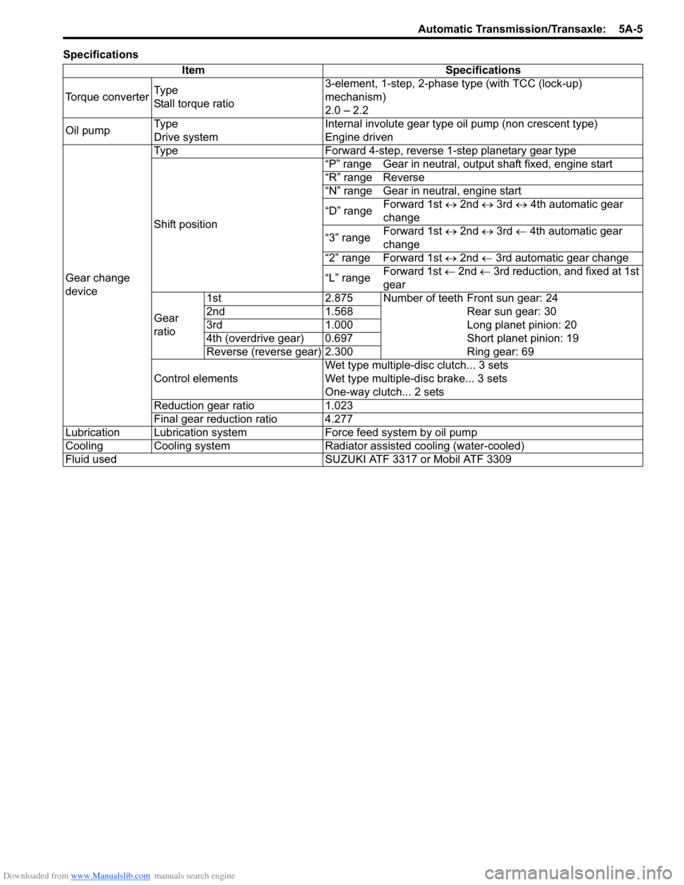
SpecificationsItem Specifications
Torque converter Ty p e
Stall torque ratio 3-element, 1-step, 2-phase type (with TCC (lock-up)
mechanism)
2.0 – 2.2
Oil pump Ty p e
Drive system Internal involute gear type oil pump (non crescent type)
Engine driven
Gear change
device Type Forward 4-step, reverse 1-step planetary gear type
Shift position
“P” range Gear in neutral, output shaft fixed, engine start
“R” range Reverse
“N” range Gear in neutral, engine start
“D” range
Forward 1st
↔ 2nd ↔ 3rd ↔ 4th automatic gear
change
“3” range Forward 1st
↔ 2nd ↔ 3rd ← 4th automatic gear
change
“2” range Forward 1st ↔ 2nd ← 3rd automatic gear change
“L” range Forward 1st
← 2nd ← 3rd reduction, and fixed at 1st
gear
Gear
ratio 1st 2.875 Number of teeth Front sun gear: 24
2nd 1.568 Rear sun gear: 30
3rd 1.000 Long planet pinion: 20
4th (overdrive gear) 0.697 Short planet pinion: 19
Reverse (reverse gear) 2.300 Ring gear: 69
Control elements Wet type multiple-disc clutch... 3 sets
Wet type multiple-d
isc brake... 3 sets
One-way clutch... 2 sets
Reduction gear ratio 1.023
Final gear reduction ratio 4.277
Lubrication Lubrication system Force feed system by oil pump
Cooling Cooling system Radiator assisted cooling (water-cooled)
Fluid used SUZUKI ATF 3317 or Mobil ATF 3309
Page 823 of 1496

Downloaded from www.Manualslib.com manuals search engine Manual Transmission/Transaxle: 5B-9
Manual Transaxle Unit Dismounting and
Remounting
S7RS0B5206009
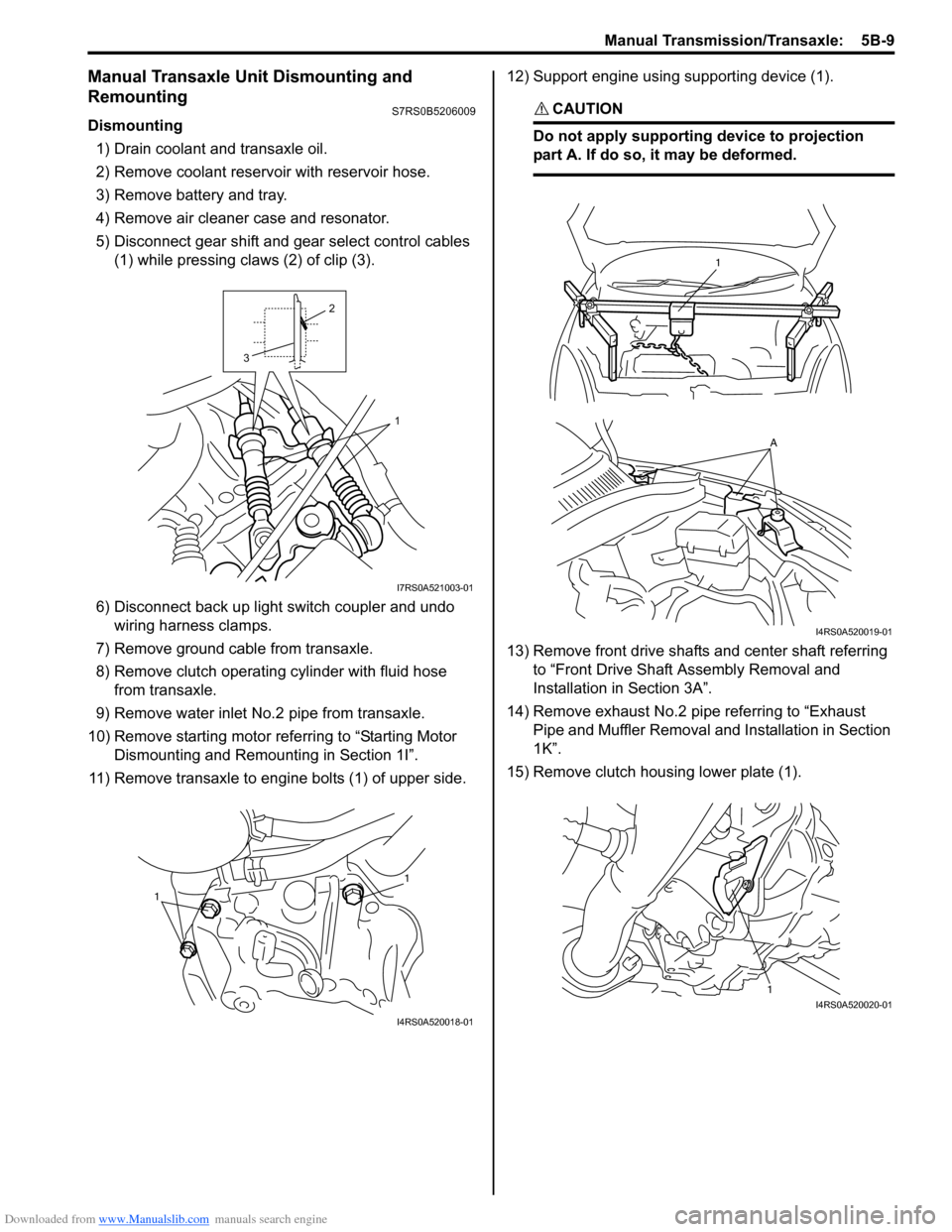
Dismounting1) Drain coolant and transaxle oil.
2) Remove coolant reservoir with reservoir hose.
3) Remove battery and tray.
4) Remove air cleaner case and resonator.
5) Disconnect gear shift and gear select control cables (1) while pressing claws (2) of clip (3).
6) Disconnect back up light switch coupler and undo wiring harness clamps.
7) Remove ground cable from transaxle.
8) Remove clutch operating cylinder with fluid hose from transaxle.
9) Remove water inlet No.2 pipe from transaxle.
10) Remove starting motor re ferring to “Starting Motor
Dismounting and Remounting in Section 1I”.
11) Remove transaxle to engine bolts (1) of upper side. 12) Support engine using supporting device (1).
CAUTION!
Do not apply supporting device to projection
part A. If do so, it may be deformed.
13) Remove front drive shafts and center shaft referring
to “Front Drive Shaft Assembly Removal and
Installation in Section 3A”.
14) Remove exhaust No.2 pipe referring to “Exhaust Pipe and Muffler Removal a nd Installation in Section
1K”.
15) Remove clutch housing lower plate (1).
1
2
3
I7RS0A521003-01
1
1
I4RS0A520018-01
1
A
I4RS0A520019-01
1I4RS0A520020-01
Page 1406 of 1496

Downloaded from www.Manualslib.com manuals search engine 10B-3 Body Electrical Control System:
Theft Deterrent LightS7RS0BA201003
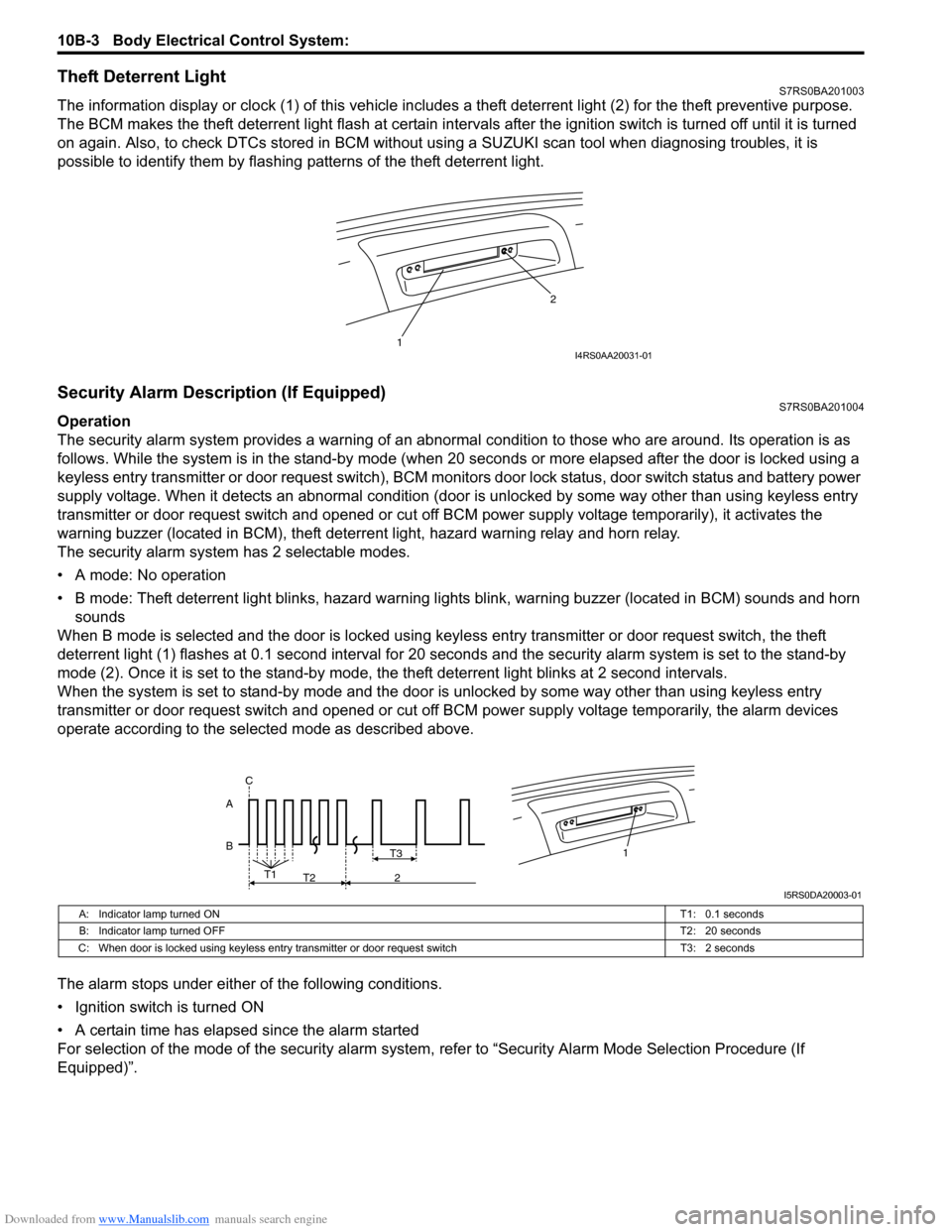
The information display or clock (1) of this vehicle includes a theft deterrent light (2) for the theft preventive purpose.
The BCM makes the theft deterrent light flash at certain interval s after the ignition switch is turned off until it is turned
on again. Also, to check DTCs stored in BCM without usin g a SUZUKI scan tool when diagnosing troubles, it is
possible to identify them by flashing patterns of the theft deterrent light.
Security Alarm Description (If Equipped)S7RS0BA201004
Operation
The security alarm system provides a warning of an abnormal condition to those who are around. Its operation is as
follows. While the system is in the stand- by mode (when 20 seconds or more elapsed after the door is locked using a
keyless entry transmitter or door request switch), BCM monitors door lock status, door switch status and battery power
supply voltage. When it detects an abnormal condition (door is unlocked by some way other than using keyless entry
transmitter or door request switch and opened or cut off BCM power supply voltage temporarily), it activates the
warning buzzer (located in BCM), theft deterr ent light, hazard warning relay and horn relay.
The security alarm system has 2 selectable modes.
• A mode: No operation
• B mode: Theft deterrent light blinks, hazard warning lights blink, warning buzzer (located in BCM) sounds and horn
sounds
When B mode is selected and the door is locked using keyl ess entry transmitter or door request switch, the theft
deterrent light (1) flashes at 0.1 second interval for 20 seconds and the se curity alarm system is set to the stand-by
mode (2). Once it is se t to the stand-by mode, the theft deterrent light blinks at 2 second intervals.
When the system is set to stand-by mode and the door is unlocked by some way other than using keyless entry
transmitter or door request switch and opened or cut off BCM power supply voltage temporarily, the alarm devices
operate according to the selected mode as described above.
The alarm stops under either of the following conditions.
• Ignition switch is turned ON
• A certain time has elapsed since the alarm started
For selection of the mode of the security alarm system , refer to “Security Alarm Mode Selection Procedure (If
Equipped)”.
1 2I4RS0AA20031-01
B A1T3
T1
T2 2
C
I5RS0DA20003-01
A: Indicator lamp turned ON
T1: 0.1 seconds
B: Indicator lamp turned OFF T2: 20 seconds
C: When door is locked using keyless entry tr ansmitter or door request switch T3: 2 seconds
Page 1445 of 1496

Downloaded from www.Manualslib.com manuals search engine Immobilizer Control System: 10C-2
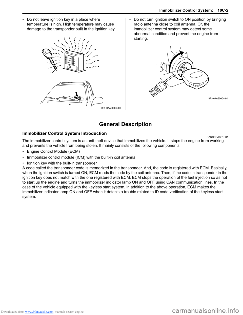
• Do not leave ignition key in a place where
temperature is high. High temperature may cause
damage to the transponder built in the ignition key. • Do not turn ignition switch to ON position by bringing
radio antenna close to coil antenna. Or, the
immobilizer control syst em may detect some
abnormal condition and prevent the engine from
starting.
General Description
Immobilizer Control System IntroductionS7RS0BA301001
The immobilizer control system is an anti-theft device that immobilizes the vehicle. It stops the engine from working
and prevents the vehicle from being stolen. It mainly consists of the following components.
• Engine Control Module (ECM)
• Immobilizer control module (ICM) with the built-in coil antenna
• Ignition key with the built-in transponder
A code called the transponder code is memorized in the tran sponder. And, the code is registered with ECM. Basically,
when the ignition switch is turned ON, ECM reads the code by the coil antenna. Then, if the code in transponder in the
ignition key does not match with the one registered with ECM, ECM stops the operati on of the fuel injection so as not
to start up the engine and turns the immobilizer indi cator lamp ON and OFF using CA N communication lines. In the
case of the vehicle equipped with the keyless start system , in addition to the above operation, ECM makes the
immobilizer indicator lamp ON and OFF when it detects a trouble related to ID code verification of the keyless start
system.
I3RH0AA30003-01
I3RH0AA30004-01