high tension SUZUKI SWIFT 2008 2.G Service Owner's Manual
[x] Cancel search | Manufacturer: SUZUKI, Model Year: 2008, Model line: SWIFT, Model: SUZUKI SWIFT 2008 2.GPages: 1496, PDF Size: 34.44 MB
Page 398 of 1496
Downloaded from www.Manualslib.com manuals search engine 1H-6 Ignition System:
Ignition Spark TestS7RS0B1804004
1) Remove air cleaner assembly with air intake pipe.
2) Disconnect all injector couplers from injectors.
WARNING!
Without disconnection of injector couplers,
combustible gas may come out from spark
plug holes during this test and may get
ignited in engine room.
3) Remove spark plug and check it for condition and
type referring to “Spark Plug Inspection”.
4) If OK, connect ignition coil coupler to ignition coil assembly and connect spark plug to ignition coil
assembly or high-tension cord. Ground spark plug. 5) Crank engine and check if each spark plug sparks.
6) If no spark is emitted, inspect the related parts as
described in “Ignition System Symptom Diagnosis”.
Repair Instructions
High-Tension Cord Removal and InstallationS7RS0B1806001
Removal
1) Remove air cleaner assembly with air intake pipe and cylinder head upper cover.
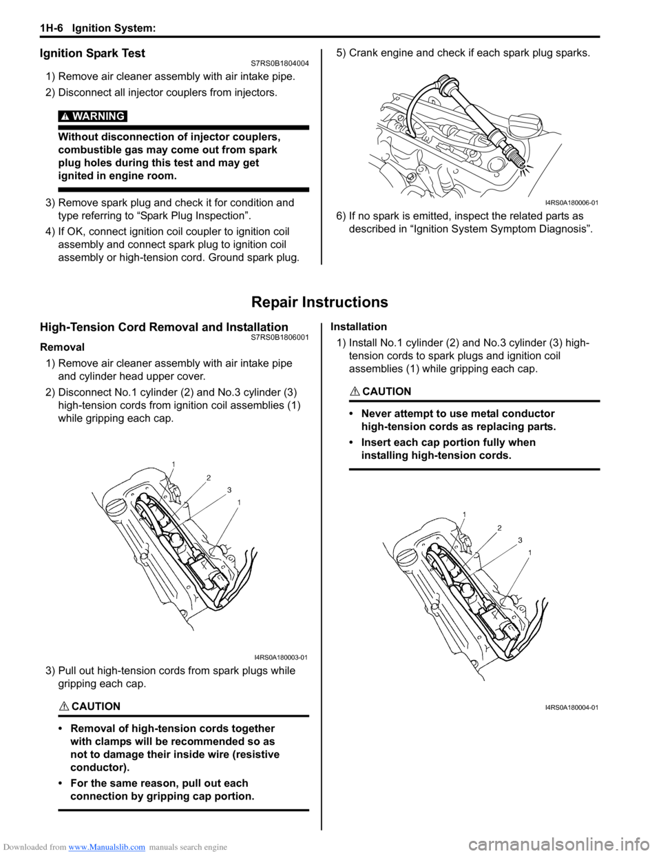
2) Disconnect No.1 cylinder (2) and No.3 cylinder (3)
high-tension cords from ignition coil assemblies (1)
while gripping each cap.
3) Pull out high-tension cords from spark plugs while gripping each cap.
CAUTION!
• Removal of high-tension cords together with clamps will be recommended so as
not to damage their inside wire (resistive
conductor).
• For the same reason, pull out each connection by gripping cap portion.
Installation
1) Install No.1 cylinder (2) and No.3 cylinder (3) high-
tension cords to spark plugs and ignition coil
assemblies (1) while gripping each cap.
CAUTION!
• Never attempt to use metal conductor high-tension cords as replacing parts.
• Insert each cap portion fully when installing high-tension cords.
I4RS0A180006-01
I4RS0A180003-01
I4RS0A180004-01
Page 399 of 1496
Downloaded from www.Manualslib.com manuals search engine Ignition System: 1H-7
High-Tension Cord InspectionS7RS0B1806002
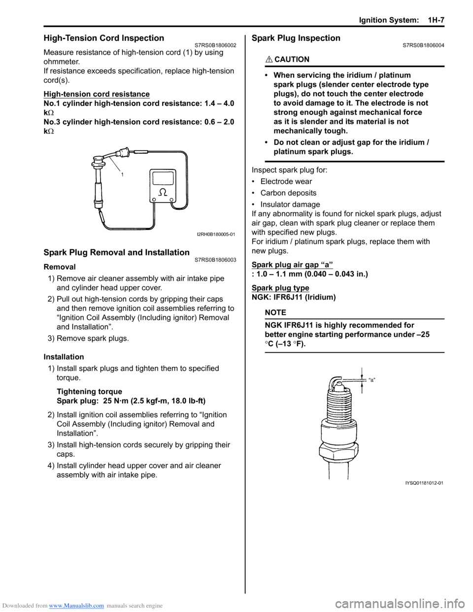
Measure resistance of high-tension cord (1) by using
ohmmeter.
If resistance exceeds specification, replace high-tension
cord(s).
High-tension cord resistance
No.1 cylinder high-tension cord resistance: 1.4 – 4.0
k Ω
No.3 cylinder high-tension cord resistance: 0.6 – 2.0
k Ω
Spark Plug Removal and InstallationS7RS0B1806003
Removal
1) Remove air cleaner assembly with air intake pipe and cylinder head upper cover.
2) Pull out high-tension cords by gripping their caps and then remove ignition coil assemblies referring to
“Ignition Coil Assembly (Inc luding ignitor) Removal
and Installation”.
3) Remove spark plugs.
Installation 1) Install spark plugs and tighten them to specified torque.
Tightening torque
Spark plug: 25 N·m (2.5 kgf-m, 18.0 lb-ft)
2) Install ignition coil assemblies referring to “Ignition Coil Assembly (Including ignitor) Removal and
Installation”.
3) Install high-tension cords securely by gripping their caps.
4) Install cylinder head upper cover and air cleaner assembly with air intake pipe.
Spark Plug InspectionS7RS0B1806004
CAUTION!
• When servicing the iridium / platinum
spark plugs (slender center electrode type
plugs), do not touch the center electrode
to avoid damage to it. The electrode is not
strong enough against mechanical force
as it is slender and its material is not
mechanically tough.
• Do not clean or adjust gap for the iridium / platinum spark plugs.
Inspect spark plug for:
• Electrode wear
• Carbon deposits
• Insulator damage
If any abnormality is found for nickel spark plugs, adjust
air gap, clean with spark plug cleaner or replace them
with specified new plugs.
For iridium / platinum spark plugs, replace them with
new plugs.
Spark plug air gap
“a”
: 1.0 – 1.1 mm (0.040 – 0.043 in.)
Spark plug type
NGK: IFR6J11 (Iridium)
NOTE
NGK IFR6J11 is highly recommended for
better engine starting performance under –25
°C (–13 °F).
I2RH0B180005-01
IYSQ01181012-01
Page 400 of 1496

Downloaded from www.Manualslib.com manuals search engine 1H-8 Ignition System:
Ignition Coil Assembly (Including ignitor)
Removal and Installation
S7RS0B1806005
Removal1) Disconnect negative (–) cable at battery.
2) Remove air cleaner assembly with air intake pipe and cylinder head upper cover.
3) Disconnect ignition coil coupler.
4) Disconnect high-tension cord (3) from ignition coil assembly (2).
5) Remove ignition coil bolts (1) and then pull out ignition coil assembly.
Installation 1) Install ignition coil assembly (2).
2) Tighten ignition coil bolts (1) to specified torque, and then connect igni tion coil coupler.
Tightening torque
Ignition coil bolt (a): 10 N·m (1.0 kgf-m, 7.5 lb-ft)
3) Install high-tension cord (3) to ignition coil assembly while gripping its cap.
4) Install cylinder head upper cover and air cleaner assembly with air intake pipe.
5) Connect negative (–) cable to battery.
Ignition Coil Assembly (Including ignitor)
Inspection
S7RS0B1806006
Measure secondary coil for resistance.
If resistance is out of specification, replace ignition coil
assembly.
Secondary coil resistance
7.5 – 10.3 k Ω at 20 °C, 68 ° F
Ignition Timing InspectionS7RS0B1806007
NOTE
• Ignition timing is not adjustable. If ignition
timing is out of specification, check
system related parts.
• Before starting engine, place transmission gear shift lever in “Neutral” (shift selector
lever to “P” range for A/T model), and set
parking brake.
1) Connect scan tool to DLC (1) with ignition switch OFF.
Special tool
(A): SUZUKI scan tool
2) Start engine and warm it up to normal operating temperature.
3) Make sure that all of electrical loads except ignition are switched off.
4) Check to be sure that idle speed is within specification referring to “Idle Speed and IAC
Throttle Valve Opening Inspection in Section 1A”
5) Fix ignition timing by using “Fixed Spark” of “Misc Test” mode on scan tool.
I2RH0B180006-01
I3RM0A180004-01
I2RH0B180007-01
(A)
1
I4RS0B180003-01
Page 401 of 1496
Downloaded from www.Manualslib.com manuals search engine Ignition System: 1H-9
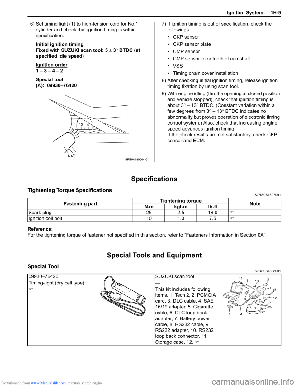
6) Set timing light (1) to high-tension cord for No.1 cylinder and check that ignition timing is within
specification.
Initial ignition timing
Fixed with SUZUKI scan tool: 5 ± 3° BTDC (at
specified idle speed)
Ignition order
1 – 3 – 4 – 2
Special tool
(A): 09930–76420 7) If ignition timing is out
of specification, check the
followings.
• CKP sensor
• CKP sensor plate
• CMP sensor
• CMP sensor rotor tooth of camshaft
• VSS
• Timing chain cover installation
8) After checking initial igniti on timing, release ignition
timing fixation by using scan tool.
9) With engine idling (throttl e opening at closed position
and vehicle stopped), check that ignition timing is
about 3 ° – 13° BTDC. (Constant variation within a
few degrees from 3 ° – 13° BTDC indicates no
abnormality but proves operation of electronic timing
control system.) Also, check that increasing engine
speed advances ignition timing.
If the check results are not satisfactory, check CKP
sensor and ECM.
Specifications
Tightening Torque SpecificationsS7RS0B1807001
Reference:
For the tightening torque of fastener not specified in this section, refer to “Fasteners Information in Section 0A”.
Special Tools and Equipment
Special ToolS7RS0B1808001
1, (A)10
0I3RB0A180004-01
Fastening part Tightening torque
Note
N ⋅mkgf-mlb-ft
Spark plug 25 2.5 18.0 �)
Ignition coil bolt 10 1.0 7.5 �)
09930–76420SUZUKI scan tool
Timing-light (dry cell type) —
�) This kit includes following
items. 1. Tech 2, 2. PCMCIA
card, 3. DLC cable, 4. SAE
16/19 adapter, 5. Cigarette
cable, 6. DLC loop back
adapter, 7. Battery power
cable, 8. RS232 cable, 9.
RS232 adapter, 10. RS232
loop back connector, 11.
Storage case, 12. �)
Page 415 of 1496
Downloaded from www.Manualslib.com manuals search engine Charging System: 1J-5
Generator Test (Undercharged Battery Check)S7RS0B1A04003
This condition, as evidenced by slow cranking or
indicator clear with dark or light yellow dot can be
caused by one or more of the following conditions even
though indicator lamp may be operating normal.
The following procedure also applies to cars with
voltmeter and ammeter.1) Make sure that undercharged condition has not been caused by accessories left on for extended period of
time.
2) Check drive belt for proper tension.
3) If battery defect is suspected, refer to “Battery Description”.
4) Inspect wiring for defects. Check all connections for tightness and cleanliness, battery cable connections
at battery, starting motor, ignition ground cable and
no “C” terminal circuit at ground.
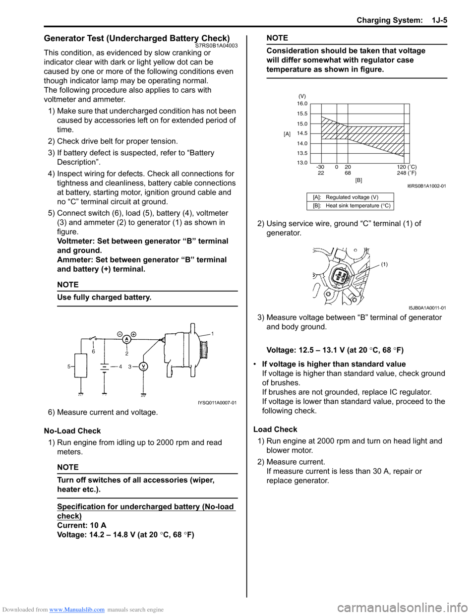
5) Connect switch (6), load (5), battery (4), voltmeter (3) and ammeter (2) to generator (1) as shown in
figure.
Voltmeter: Set between generator “B” terminal
and ground.
Ammeter: Set between generator “B” terminal
and battery (+) terminal.
NOTE
Use fully charged battery.
6) Measure current and voltage.
No-Load Check 1) Run engine from idling up to 2000 rpm and read meters.
NOTE
Turn off switches of all accessories (wiper,
heater etc.).
Specification for undercharged battery (No-load
check)
Current: 10 A
Voltage: 14.2 – 14.8 V (at 20 °C, 68 °F)
NOTE
Consideration should be taken that voltage
will differ somewhat with regulator case
temperature as shown in figure.
2) Using service wire, ground “C” terminal (1) of
generator.
3) Measure voltage between “B” terminal of generator and body ground.
Voltage: 12.5 – 13.1 V (at 20 °C, 68 °F)
• If voltage is higher than standard value
If voltage is higher than standard value, check ground
of brushes.
If brushes are not grounded, replace IC regulator.
If voltage is lower than standard value, proceed to the
following check.
Load Check 1) Run engine at 2000 rpm and turn on head light and blower motor.
2) Measure current. If measure current is less than 30 A, repair or
replace generator.
IYSQ011A0007-01
[A]: Regulated voltage (V)
[B]: Heat sink temperature ( °C)
16.0
15.5
15.0
14.5
14.0
13.5
13.0
-30 0 20
[A]
[B]
68
22120 (˚C)
248 (˚F)
(V)
I6RS0B1A1002-01
I5JB0A1A0011-01
Page 417 of 1496
Downloaded from www.Manualslib.com manuals search engine Charging System: 1J-7
With Charging Equipment
CAUTION!
When jump starting engine with charging
equipment, be sure equipment used is 12-
volt and negative ground. Do not use 24-volt
charging equipment. Using such equipment
can cause serious damage to electrical
system or electronic parts.
Battery Dismounting and RemountingS7RS0B1A06002
WARNING!
When handling battery, following safety
precautions should be followed:
• Hydrogen gas is produced by battery. A flame or spark near battery may cause the
gas to ignite.
• Battery fluid is highly acidic. Avoid spilling on clothing or other fabric. Any spilled
electrolyte should be flushed with large
quantity of water and cleaned immediately.
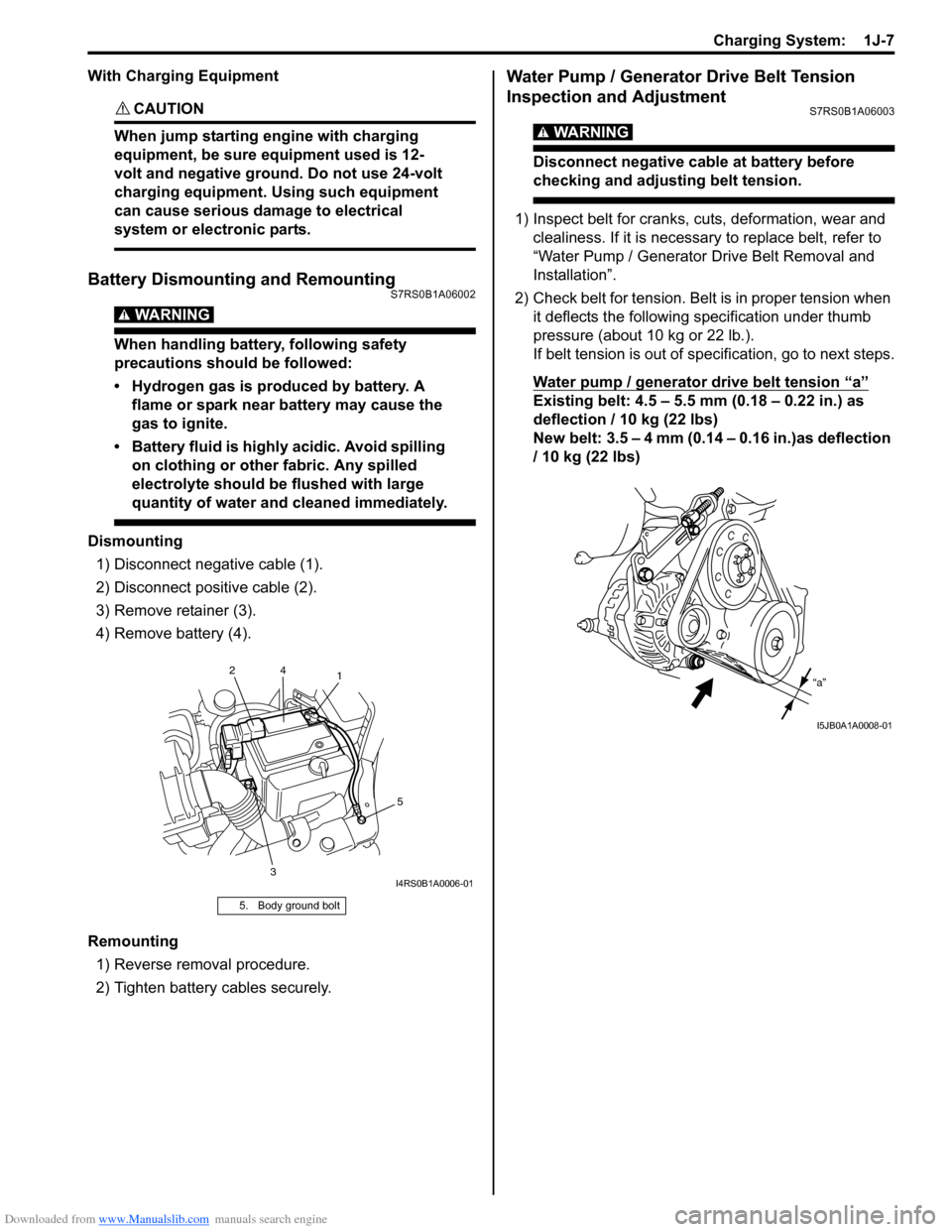
Dismounting
1) Disconnect negative cable (1).
2) Disconnect positive cable (2).
3) Remove retainer (3).
4) Remove battery (4).
Remounting 1) Reverse removal procedure.
2) Tighten battery cables securely.
Water Pump / Generator Drive Belt Tension
Inspection and Adjustment
S7RS0B1A06003
WARNING!
Disconnect negative cable at battery before
checking and adjusting belt tension.
1) Inspect belt for cranks, cuts, deformation, wear and clealiness. If it is necessary to replace belt, refer to
“Water Pump / Generator Drive Belt Removal and
Installation”.
2) Check belt for tension. Belt is in proper tension when it deflects the following specification under thumb
pressure (about 10 kg or 22 lb.).
If belt tension is out of spec ification, go to next steps.
Water pump / generator drive belt tension
“a”
Existing belt: 4.5 – 5.5 mm (0.18 – 0.22 in.) as
deflection / 10 kg (22 lbs)
New belt: 3.5 – 4 mm (0.14 – 0.16 in.)as deflection
/ 10 kg (22 lbs)
5. Body ground bolt
1
3 5
2
4
I4RS0B1A0006-01
“a”
I5JB0A1A0008-01
Page 958 of 1496

Downloaded from www.Manualslib.com manuals search engine 7B-10 Air Conditioning System: Manual Type
Abnormal Noise from Tension Pulley
Abnormal Noise from A/C Evaporator
Abnormal Noise from Blower Motor
A/C System Performance InspectionS7RS0B7214003
1) Confirm that vehicle and environmental conditions are as follows.
• Vehicle is put indoors.
• Ambient temperature is within 25 – 35 °C (77 – 95
° F).
• Relative humidity is within 30 – 70%.
• There is no wind indoors.
• HVAC unit is normal.
• Blower motor is normal.
• There is no air leakage from air ducts.
• Condenser fins are clean.
• Air filter in HVAC unit is not clogged with dirt and
dust.
• Battery voltage is about 12 V.
• Radiator cooling fan operates normally.
2) Make sure that high pressure valve (1) and low pressure valve (2) of manifold gauge are firmly
closed.
3) Connect high pressure charging hose (3) to high pressure service valve (5) on vehicle and low
pressure charging hose (4) to low pressure service
valve (6).
4) Bleed the air in charging hoses (3) and (4) by loosening their nuts respectively utilizing the
refrigerant pressure. When a hissing sound is heard,
immediately tighten nut.
CAUTION!
Do not connect high and low pressure
charging hoses in reverse.
Condition Possible cause Correction / Reference Item
Clattering noise is heard
from pulley Worn or damaged bearing
Replace tension pulley.
Pulley cranks upon
contact Cracked or loose bracket
Replace or retighten bracket.
ConditionPossible cause Correction / Reference Item
Whistling sound is heard
from A/C evaporator Depending on the combination of the
interior / exterior temperatures, engine
rpm and refrigerant pressure, the
refrigerant flowing out of the expansion
valve may, under certain conditions,
make a whistling sound At times, slightly decrea
sing refrigerant volume
may stop this noise.
Inspect expansion valve and replace if faulty.
Condition Possible cause Correction / Reference Item
Blower motor emits a
chirping sound in
proportion to its speed of
rotation Worn or damaged motor brushes or
commutator
Replace blower motor.
Fluttering noise or large
droning noise is heard
from blower motor Leaves or other debris introduced from
fresh air inlet to blower motor
Remove debris and make sure that the screen
at fresh air inlet is intact.
53
2
1
4 6
I4RS0A720006-01
Page 1029 of 1496
Downloaded from www.Manualslib.com manuals search engine Table of Contents 8- i
8
Section 8
CONTENTS
Restraint
Precautions ................................................. 8-1
Precautions............................................................. 8-1
Precautions on Restraint ....................................... 8-1
Seat Belts .......... ............................... ........ 8A-1
Precautions........................................................... 8A-1
Precautions on Service a nd Diagnosis of Seat
Belt .................................................................... 8A-1
General Description ............................................. 8A-1 Seat Belt Construction ........................................ 8A-1
Diagnostic Information and Procedures ............ 8A-2 Repair and Inspection Required after Accident ............................................................ 8A-2
Repair Instructions .............................................. 8A-3 Front Seat Belt Components ............................... 8A-3
Front Seat Belt Removal and Installation ............ 8A-4
Front Seat Belt Inspection ................................... 8A-4
Rear Seat Belt Components ............................... 8A-6
Rear Seat Belt Removal and Installation ............ 8A-7
Rear Seat Belt Inspection ................................... 8A-7
Specifications ....................................................... 8A-7
Tightening Torque Specifications ........................ 8A-7
Air Bag System ............... ......................... 8B-1
Precautions........................................................... 8B-1
Precautions on Service and Diagnosis of Air Bag System....................................................... 8B-1
Precautions on Handling and Storage of Air Bag System Components . ................................ 8B-2
Precautions on Disposal of Air Bag and Seat
Belt Pretensioner .............................................. 8B-5
General Description ............................................. 8B-5 Air Bag System Construction .............................. 8B-5
Air Bag System Input / Output Table .................. 8B-6
Schematic and Routing Diagram ........................ 8B-7 Air Bag System Wiring Circuit Diagram .............. 8B-7
Component Locatio n ........................................... 8B-9
Air Bag System Components, Wiring and Connectors Location ......................................... 8B-9
Diagnostic Information and Procedures .......... 8B-10 Air Bag Diagnostic System Check .................... 8B-10
Air Bag Diagnostic System Check Flow ............ 8B-10
DTC Table ......................................................... 8B-11
DTC Check ....................................................... 8B-12 DTC Clearance ................................................. 8B-12
Scan Tool Data ................................................. 8B-13
“AIR BAG” Warning Right Comes ON Steady .. 8B-13
“AIR BAG” Warning Right Does Not Come
ON ................................................................... 8B-15
“AIR BAG” Warning Right Flashes .................... 8B-16
DTC B1013: SDM fault...................................... 8B-17
DTC B1014: “AIR BAG” Warning Right Circuit Failure ............................................................. 8B-17
DTC B1016: Power Source Voltage High ......... 8B-18
DTC B1017: Power Source Voltage Low .......... 8B-20
DTC B1021: Front Air Bag Module Deployed ... 8B-22
DTC B1024 / B1025: Side-Air Bag (Driver / Passenger) Deployed...................................... 8B-22
DTC B1026: Pretensioner Activated ................. 8B-23
DTC B1027: Reusable Number Exceeded ....... 8B-24
DTC B1031: Driver Air Bag Initiator Circuit
Resistance High .............................................. 8B-24
DTC B1032: Driver Air Bag Initiator Circuit
Resistance Low ............................................... 8B-29
DTC B1033: Driver Air Bag Initiator Circuit
Short to Ground............................................... 8B-34
DTC B1034: Driver Air Bag Initiator Circuit
Short to Power Circuit .... ................................. 8B-39
DTC B1041: Passenger Air Bag Initiator Circuit Resistance High ................................... 8B-44
DTC B1042: Passenger Air Bag Initiator Circuit Resistance Low.................................... 8B-47
DTC B1043: Passenger Air Bag Initiator Circuit Short to Ground ................................... 8B-50
DTC B1044: Passenger Air Bag Initiator Circuit Short to Power Circ uit .......................... 8B-53
DTC B1051 / B1055: Driver / Passenger Pretensioner Initiator Circuit Resistance
High ................................................................. 8B-56
DTC B1052 / B1056: Driver / Passenger Pretensioner Initiator Circu it Resistance Low .. 8B-58
DTC B1053 / B1057: Driver / Passenger Pretensioner Initiator Circuit Short to Ground .. 8B-60
DTC B1054 / B1058: Driver / Passenger Pretensioner Initiator Circuit Short to Power
Circuit .............................................................. 8B-62
DTC B1061 / B1065: Driver / Passenger Side- Air Bag Initiator Circuit Resistance High ......... 8B-64
Page 1030 of 1496
Downloaded from www.Manualslib.com manuals search engine 8-ii Table of Contents
DTC B1062 / B1066: Driver / Passenger Side-Air Bag Initiator Circuit Resistance Low .......... 8B-67
DTC B1063 / B1067: Driver / Passenger Side- Air Bag Initiator Circuit S hort to Ground .......... 8B-70
DTC B1064 / B1068: Driver / Passenger Side- Air Bag Initiator Circu it Short to Power
Circuit .............................................................. 8B-73
DTC B1071: Forward-Sensor Performance Problem ........................................................... 8B-76
DTC B1072: Forward-Sensor Communication Error ................................................................ 8B-76
DTC B1073: Forward-Sensor Circuit Short to Ground ............................................................ 8B-76
DTC B1074: Forward-Sensor Circuit Short to Power Circuit or Open ..................................... 8B-78
DTC B1081 / B1091: Driver / Passenger Side- Sensor Performance Probl em ......................... 8B-80
DTC B1082 / B1092: Driver / Passenger Side- Sensor Communication Erro r .......................... 8B-80
DTC B1083 / B1093: Driver / Passenger Side- Sensor Circuit Short to Ground ....................... 8B-80
DTC B1084 / B1094: Driver / Passenger Side- Sensor Circuit Short to Power Circuit or
Open ............................................................... 8B-81
DTC B1085 / B1095: Wrong Side-Sensor (Driver Side / Passenger) ID ........................... 8B-83
DTC B1361 / B1365: Driver / Passenger Side Curtain-Air Bag Initiator Circuit Resistance
High ................................................................. 8B-84
DTC B1362 / B1366: Driver / Passenger Side Curtain-Air Bag Initiator Circuit Resistance
Low ................................................................. 8B-86
DTC B1363 / B1367: Driver / Passenger Side Curtain-Air Bag Initiator Circuit Short to
Ground ............................................................ 8B-88
DTC B1364 / B1368: Driver / Passenger Side Curtain-Air Bag Initiator Circuit Short to
Power Circuit ................................................... 8B-90
Contact Coil Cable and Its Circuit Check .......... 8B-93 Inspection of Intermittent and Poor
Connections .................................................... 8B-95
Repair and Inspection Required after Accident .......................................................... 8B-96
Repair Instructions ............ ................................8B-98
Disabling Air Bag System.................................. 8B-98
Enabling Air Bag System .................................. 8B-99
SDM Removal and Installation ........................ 8B-100
SDM Inspection ............................................... 8B-101
Driver Air Bag (Inflato r) Module Removal and
Installation ..................................................... 8B-101
Driver Air Bag (Inflator) Module Inspection ..... 8B-103
Passenger Air Bag (Inflator) Module Removal and Installation .............................................. 8B-103
Passenger Air Bag (I nflator) Module
Inspection ...................................................... 8B-105
Side-Air Bag (Inflator) Module Removal and
Installation ..................................................... 8B-105
Side-Air Bag (Inflator) Inspection .................... 8B-107
Side Curtain-Air Bag (Inflator) Module Removal and Installation ............................... 8B-107
Side Curtain-Air Bag (Inflator) Module Inspection ...................................................... 8B-109
Forward-Sensor Removal and Installation ...... 8B-109
Forward-Sensor In spection ............................. 8B-110
Side-Sensor Removal and Installation ............ 8B-110
Side-Sensor Inspection ................................... 8B-111
Passenger Air Bag (Inflator) Module Repair
Harness Installation....................................... 8B-112
Air Bag (Inflator) Module and Seat Belt Pretensioner Disposal ................................... 8B-113
Deployed Air Bag (Inflator) Module and Activated Seat Belt Pretensioner Disposal.... 8B-124
Specifications .................. .................................8B-125
Tightening Torque Specifications .................... 8B-125
Special Tools and Equipmen t .........................8B-125
Use of Special Tools ....................................... 8B-125
Recommended Service Material ..................... 8B-127
Special Tool .................................................... 8B-127
Page 1041 of 1496
Downloaded from www.Manualslib.com manuals search engine Air Bag System: 8B-3
• Never attempt disassembly of the air bag (inflator) modules.
• If any abnormality is found, be sure to replace it with
new one as an assembly.
• When an abnormality is noted as existing in the live (undeployed) air bag (inflator) module, be sure to
deploy it before discarding it.
• When grease, cleaning agent, oil, water, etc., got on the air bag (inflator) modules (driver, passenger, side
of both sides and curtain of both sides), wipe it off
immediately with a dry cloth.
• If air bag (inflator) module was dropped from a height of 90 cm (3 ft) or more, it should be replaced with a
new one as an assembly.
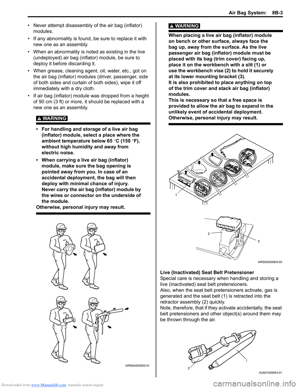
WARNING!
• For handling and storage of a live air bag (inflator) module, select a place where the
ambient temperature below 65 °C (150 ° F),
without high humidity and away from
electric noise.
• When carrying a live air bag (inflator) module, make sure the bag opening is
pointed away from you. In case of an
accidental deployment, the bag will then
deploy with minimal chance of injury.
Never carry the air bag (inflator) module by
the wires or connector on the underside of
the module.
Otherwise, personal injury may result.
WARNING!
When placing a live air bag (inflator) module
on bench or other surface, always face the
bag up, away from the surface. As the live
passenger air bag (inflator) module must be
placed with its bag (trim cover) facing up,
place it on the workbench with a slit (1) or
use the workbench vise (2) to hold it securely
at its lower mounting bracket (3).
It is also prohibited to place anything on top
of the trim cover and stack air bag (inflator)
modules.
This is necessary so that a free space is
provided to allow the air bag to expand in the
unlikely event of accidental deployment.
Otherwise, personal injury may result.
Live (Inactivated) Seat Belt Pretensioner
Special care is necessary when handling and storing a
live (inactivated) seat belt pretensioners.
Also, when the seat belt pretensioners activate, gas is
generated and the seat belt (1) is retracted into the
retractor assembly (2) quickly.
Note, therefore, that if they activate accidentally, the seat
belt pretensioners and other object(s) around them may
be thrown through the air.
I4RS0A820002-01
1
2
3
I4RS0A820003-02
I3JA01820043-01