main harness SUZUKI SWIFT 2008 2.G Service Owner's Manual
[x] Cancel search | Manufacturer: SUZUKI, Model Year: 2008, Model line: SWIFT, Model: SUZUKI SWIFT 2008 2.GPages: 1496, PDF Size: 34.44 MB
Page 611 of 1496
Downloaded from www.Manualslib.com manuals search engine Electronic Stability Program: 4F-37
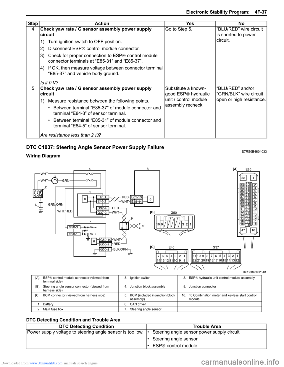
DTC C1037: Steering Angle Sensor Power Supply FailureS7RS0B4604033
Wiring Diagram
DTC Detecting Condition and Trouble Area4
Check yaw rate / G sensor assembly power supply
circuit
1) Turn ignition switch to OFF position.
2) Disconnect ESP ® control module connector.
3) Check for proper connection to ESP ® control module
connector terminals at “E85-31” and “E85-37”.
4) If OK, then measure voltage between connector terminal “E85-37” and vehicle body ground.
Is it 0 V? Go to Step 5. “BLU/RED” wire circuit
is shorted to power
circuit.
5 Check yaw rate / G sensor assembly power supply
circuit
1) Measure resistance between the following points.
• Between terminal “E85-37” of module connector and terminal “E84-3” of sensor terminal.
• Between terminal “E85-31” of module connector and terminal “E84-5” of sensor terminal.
Are resistance less than 2
Ω? Substitute a known-
good ESP
® hydraulic
unit / control module
assembly recheck. “BLU/RED” and/or
“GRN/BLK” wire circuit
open or high resistance.
Step
Action YesNo
[A]
E85
161
15
2
3
4
5
6
7
8
9
10
11
12
13
14
17
18
19
20
21
22
23
24
25
26
27
28
29
30
31
3233
34
35
36
37
38
39
40
41
42
43
44
45
46
47
[C] G37
E46
124
53
67
891011121314124
53
67
891011
1213141516171819202122
WHTGRN
3
E85-13
E85-44REDWHT65E46-1E46-2
4 8
6
BLK/ORN
REDWHT
REDWHT
G37-4G37-2
G50-10G50-9
G50-2
6
2
1
7 910
G50-1
G50-3
GRN/ORN
WHT/RED
WHT
[B]
G50
109 321
I6RS0B460020-01
[A]: ESP® control module connector (viewed from
terminal side) 3. Ignition switch 8. ESP
® hydraulic unit control module assembly
[B]: Steering angle sensor connector (viewed from harness side) 4. Junction block assembly 9. Junction connector
[C]: BCM connector (viewed from harnes s side) 5. BCM (included in junction block
assembly) 10. To Combination meter and keyless start control
module
1. Battery 6. CAN driver
2. Main fuse box 7. Steering angle sensor
DTC Detecting Condition Trouble Area
Power supply voltage to steering angle sensor is to o low. • Steering angle sensor power supply circuit
• Steering angle sensor
• ESP® control module
Page 618 of 1496
Downloaded from www.Manualslib.com manuals search engine 4F-44 Electronic Stability Program:
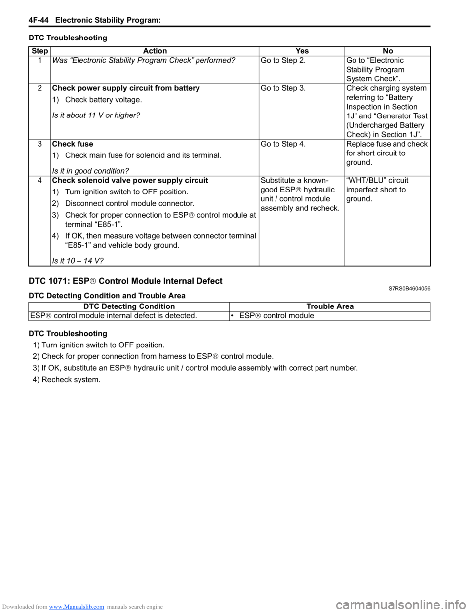
DTC Troubleshooting
DTC 1071: ESP® Control Module Internal DefectS7RS0B4604056
DTC Detecting Condition and Trouble Area
DTC Troubleshooting
1) Turn ignition switch to OFF position.
2) Check for proper connection from harness to ESP ® control module.
3) If OK, substitute an ESP ® hydraulic unit / control module assembly with correct part number.
4) Recheck system.
Step
Action YesNo
1 Was “Electronic Stability Pr ogram Check” performed? Go to Step 2.Go to “Electronic
Stability Program
System Check”.
2 Check power supply circuit from battery
1) Check battery voltage.
Is it about 11 V or higher? Go to Step 3.
Check charging system
referring to “Battery
Inspection in Section
1J” and “Generator Test
(Undercharged Battery
Check) in Section 1J”.
3 Check fuse
1) Check main fuse for solenoid and its terminal.
Is it in good condition? Go to Step 4.
Replace fuse and check
for short circuit to
ground.
4 Check solenoid valve power supply circuit
1) Turn ignition switch to OFF position.
2) Disconnect control module connector.
3) Check for proper connection to ESP® control module at
terminal “E85-1”.
4) If OK, then measure voltage between connector terminal “E85-1” and vehicle body ground.
Is it 10 – 14 V? Substitute a known-
good ESP
® hydraulic
unit / control module
assembly and recheck. “WHT/BLU” circuit
imperfect short to
ground.
DTC Detecting Condition
Trouble Area
ESP ® control module internal defect is detected. • ESP ® control module
Page 645 of 1496
Downloaded from www.Manualslib.com manuals search engine Automatic Transmission/Transaxle: 5A-1
Transmission / Transaxle
Automatic Transmission/Transaxle
Precautions
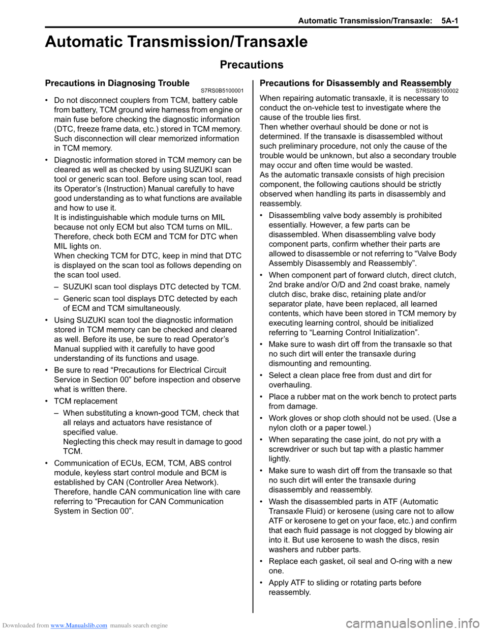
Precautions in Diagnosing TroubleS7RS0B5100001
• Do not disconnect couplers from TCM, battery cable from battery, TCM ground wire harness from engine or
main fuse before checking the diagnostic information
(DTC, freeze frame data, etc.) stored in TCM memory.
Such disconnection will clea r memorized information
in TCM memory.
• Diagnostic information stored in TCM memory can be cleared as well as checked by using SUZUKI scan
tool or generic scan tool. Before using scan tool, read
its Operator’s (Instruction) Manual carefully to have
good understanding as to what functions are available
and how to use it.
It is indistinguishable wh ich module turns on MIL
because not only ECM but also TCM turns on MIL.
Therefore, check both ECM and TCM for DTC when
MIL lights on.
When checking TCM for DTC, keep in mind that DTC
is displayed on the scan tool as follows depending on
the scan tool used.
– SUZUKI scan tool displays DTC detected by TCM.
– Generic scan tool displays DTC detected by each of ECM and TCM simultaneously.
• Using SUZUKI scan tool the diagnostic information stored in TCM memory can be checked and cleared
as well. Before its use, be sure to read Operator’s
Manual supplied with it carefully to have good
understanding of its functions and usage.
• Be sure to read “Precautions for Electrical Circuit Service in Section 00” befo re inspection and observe
what is written there.
• TCM replacement
– When substituting a known-good TCM, check that all relays and actuators have resistance of
specified value.
Neglecting this check may result in damage to good
TCM.
• Communication of ECUs , ECM, TCM, ABS control
module, keyless start control module and BCM is
established by CAN (Controller Area Network).
Therefore, handle CAN communication line with care
referring to “Precaution for CAN Communication
System in Section 00”.
Precautions for Disassembly and ReassemblyS7RS0B5100002
When repairing automatic transaxle, it is necessary to
conduct the on-vehicle test to investigate where the
cause of the trouble lies first.
Then whether overhaul should be done or not is
determined. If the transaxle is disassembled without
such preliminary procedure, not only the cause of the
trouble would be unknown, but also a secondary trouble
may occur and often time would be wasted.
As the automatic transaxle consists of high precision
component, the following cautions should be strictly
observed when handling its parts in disassembly and
reassembly.
• Disassembling valve body assembly is prohibited
essentially. However, a few parts can be
disassembled. When disassembling valve body
component parts, confirm whether their parts are
allowed to disassemble or not referring to “Valve Body
Assembly Disassembly and Reassembly”.
• When component part of forward clutch, direct clutch, 2nd brake and/or O/D and 2nd coast brake, namely
clutch disc, brake disc, retaining plate and/or
separator plate, have been replaced, all learned
contents, which have been stored in TCM memory by
executing learning control, should be initialized
referring to “Learning Control Initialization”.
• Make sure to wash dirt off from the transaxle so that no such dirt will enter the transaxle during
dismounting and remounting.
• Select a clean place free from dust and dirt for overhauling.
• Place a rubber mat on the work bench to protect parts from damage.
• Work gloves or shop cloth should not be used. (Use a nylon cloth or a paper towel.)
• When separating the case joint, do not pry with a screwdriver or such but tap with a plastic hammer
lightly.
• Make sure to wash dirt off from the transaxle so that no such dirt will enter the transaxle during
disassembly and reassembly.
• Wash the disassembled parts in ATF (Automatic Transaxle Fluid) or kerosene (using care not to allow
ATF or kerosene to get on your face, etc.) and confirm
that each fluid passage is not clogged by blowing air
into it. But use kerosene to wash the discs, resin
washers and rubber parts.
• Replace each gasket, oil seal and O-ring with a new one.
• Apply ATF to sliding or rotating parts before
reassembly.
Page 662 of 1496

Downloaded from www.Manualslib.com manuals search engine 5A-18 Automatic Transmission/Transaxle:
Visual InspectionS7RS0B5104002
Visually check the following parts and systems.
Malfunction Indicator Lamp (MIL) CheckS7RS0B5104003
Refer to the same item in “Malfunction Indicator Lam p (MIL) Check in Section 1A” for checking procedure.
Transmission Warning Light CheckS7RS0B5104004
1) Turn ignition switch ON.
2) Check that transmission warning light lights for about 2 – 4 sec. and then goes OFF.
If anything faulty is found, advance “Transmission Warn ing Light Circuit Check – Light Does Not Come “ON” at
Ignition Switch ON” or “Transmission Warning Light Circu it Check – Light Remains “ON” at Ignition Switch ON”.
Inspection item Referring
• A/T fluid ----- level, leakage, color “Automatic Transaxle Fluid Level Inspection in Section 0B”
• A/T fluid hoses ----- disconnection, looseness, deterioration “A/T Fluid Cooler Hoses Replacement”
• A/T select cable ----- installation “S elect Cable Removal and Installation”
• Engine oil ----- level, leakage “Engine Oil and Filter Change in Section 0B”
• Engine coolant ----- level, leakage “Engine Coolant Change in Section 0B”
• Engine mountings ----- play, looseness, damage “Engine Assembly Removal and Installation in Section 1D”
• Suspension ----- play, looseness “Suspension, Wheels and Tires Symptom Diagnosis in Section 2A”
• Drive shafts ----- damage “Front Drive Shaft Assembly On-Vehicle Inspection in Section 3A”
• Battery ----- indicator condition, corrosion of terminal “Battery Inspection in Section 1J”
• Connectors of electric wire harness ----- disconnection, friction “Electronic Shift Control System Components
Location”
• Fuses ----- burning
• Parts ----- installation, damage
• Bolts ----- looseness
• Other parts that can be checked visually
Also check the following items at engine start, if possible.
• Transmission warning light (if equipped) ----- Operation “Transmission Warning Light Check”
• Malfunction indicator lamp ----- Operation “Malfunction Indicator Lamp (MIL) Check”
• Charge warning lamp ----- Operation “Generator Symptom Diagnosis in Section 1J”
• Engine oil pressure warning lamp ----- Operation “Oil Pressure Warning Ligh t Symptom Diagnosis in
Section 9C”
• Engine coolant temp. meter ----- Operation “Engine Coolant Temperature (ECT) Meter
Symptom Diagnosis in Section 9C”
• Other parts that can be checked visually
I4RS0A510008-01
Page 886 of 1496
Downloaded from www.Manualslib.com manuals search engine 6C-4 Power Assisted Steering System:
Schematic and Routing Diagram
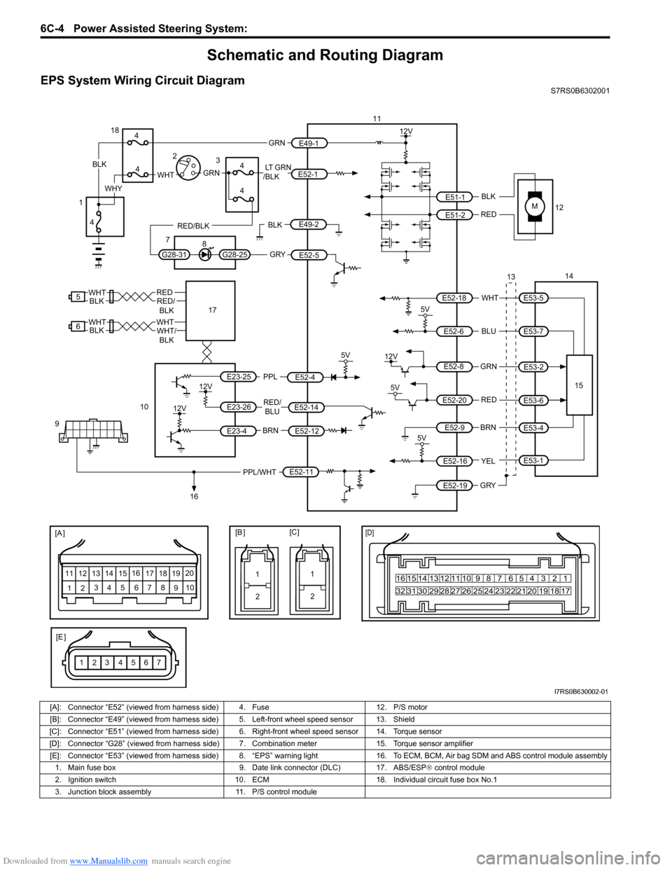
EPS System Wiring Circuit DiagramS7RS0B6302001
M
5V
BRNRED/
BLU
BLK
RED
WHT
BLU
GRN
BRN YEL
E52-11
E52-14E52-12
E23-4
E23-26
E23-25 E51-1
E51-2
E52-18
E53-5
E53-7
E52-6
E52-8
E53-2
E52-9
E52-16
E52-19
GRY
PPL/WHT
[A ]
[E ]
12 3
4 5 67
89
11
10
12 13
141516
17 18 19 20
1
2
[B ][C ]
1210 9 8 7654 3 21
16 15 14 13 12 11
26 25 24 2322 21 20 19 18 17
32 31 30 29 28 27
[D]
5V
PPL
E52-4
11
12
13 14
15
10
9
16
12V
5V
5V
12V
REDE52-20E53-6
E53-4
E53-1
7654321
5
REDRED/
BLKWHT
6WHTWHT/BLKWHTBLK
12V
12V
17BLK
GRY
LT GRN
/BLK
E52-1
E52-5
E49-1
GRNGRNWHTBLK
WHY
G28-25G28-31
RED/BLK
18
3
4
4
7 8
4
4
1 2
4
E49-2BLK
I7RS0B630002-01
[A]: Connector “E52” (viewed from harness side) 4. Fuse 12. P/S motor
[B]: Connector “E49” (viewed from harness side ) 5. Left-front wheel speed sensor 13. Shield
[C]: Connector “E51” (viewed from harness side) 6 . Right-front wheel speed sensor 14. Torque sensor
[D]: Connector “G28” (viewed from harness side) 7. Combination meter 15. Torque sensor amplifier
[E]: Connector “E53” (viewed from harness side) 8. “EPS” warning light16. To ECM, BCM, Air bag SDM and ABS control module assembly
1. Main fuse box 9. Date link connector (DLC) 17. ABS/ESP ® control module
2. Ignition switch 10. ECM18. Individual circuit fuse box No.1
3. Junction block assembly 11. P/S control module
Page 887 of 1496
Downloaded from www.Manualslib.com manuals search engine Power Assisted Steering System: 6C-5
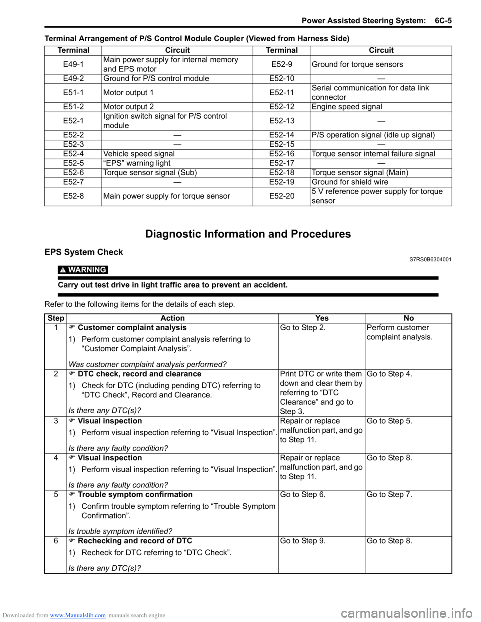
Terminal Arrangement of P/S Control Module Coupler (Viewed from Harness Side)
Diagnostic Information and Procedures
EPS System CheckS7RS0B6304001
WARNING!
Carry out test drive in light traffic area to prevent an accident.
Refer to the following items for the details of each step.Terminal Circuit Terminal Circuit
E49-1 Main power supply for internal memory
and EPS motor E52-9 Ground for torque sensors
E49-2 Ground for P/S control module E52-10 —
E51-1 Motor output 1 E52-11 Serial communication for data link
connector
E51-2 Motor output 2 E52-12 Engine speed signal
E52-1 Ignition switch signal for P/S control
module E52-13 —
E52-2 — E52-14 P/S operation signal (idle up signal)
E52-3 — E52-15 —
E52-4 Vehicle speed signal E52-16 Torque sensor internal failure signal
E52-5 “EPS” warning light E52-17 —
E52-6 Torque sensor signal (Sub) E52-18 Torque sensor signal (Main)
E52-7 — E52-19 Ground for shield wire
E52-8 Main power supply for torque sensor E52-20 5 V reference power supply for torque
sensor
Step
Action YesNo
1 �) Customer complaint analysis
1) Perform customer complaint analysis referring to “Customer Complaint Analysis”.
Was customer complaint analysis performed? Go to Step 2.
Perform customer
complaint analysis.
2 �) DTC check, record and clearance
1) Check for DTC (including pending DTC) referring to “DTC Check”, Record and Clearance.
Is there any DTC(s)? Print DTC or write them
down and clear them by
referring to “DTC
Clearance” and go to
St ep 3 .Go to Step 4.
3 �) Visual inspection
1) Perform visual inspection referring to “Visual Inspection”.
Is there any faulty condition? Repair or replace
malfunction part, and go
to Step 11.
Go to Step 5.
4 �) Visual inspection
1) Perform visual inspection referring to “Visual Inspection”.
Is there any faulty condition? Repair or replace
malfunction part, and go
to Step 11.
Go to Step 8.
5 �) Trouble symptom confirmation
1) Confirm trouble symptom referring to “Trouble Symptom Confirmation”.
Is trouble symptom identified? Go to Step 6.
Go to Step 7.
6 �) Rechecking and record of DTC
1) Recheck for DTC referring to “DTC Check”.
Is there any DTC(s)? Go to Step 9.
Go to Step 8.
Page 890 of 1496
Downloaded from www.Manualslib.com manuals search engine 6C-8 Power Assisted Steering System:
Step 2: DTC Check, Record and Clearance
First, check DTC, referring to “DTC Check”. If DTC is
indicated, print it or write them down and then clear them
by referring to “DTC Clearance”. DTC indicates
malfunction that occurred in the system but does not
indicate whether it exists now or it occurred in the past
and the normal condition has been restored now. To
check which case applies, check the symptom in
question according to Step 5 and recheck DTC
according to Step 6 and 7.
Attempt to diagnose a trouble based on DTC in this step
only or failure to clear the DTC in this step will lead to
incorrect diagnosis, trouble diagnosis of a normal circuit
or difficulty in troubleshooting.
Step 3 and 4: Visual Inspection
As a preliminary step, be sure to perform visual check of
the items that support proper function of the P/S system
referring to “Visual Inspection”.
Step 5: Trouble Symptom Confirmation
Based on information obtained in “Step 1: Customer
Complaint Analysis: ” and “S tep 2: DTC Check, Record
and Clearance: ”, confirm trouble symptoms. Also,
reconfirm trouble symptom by performing test drive and
turning steering wheel fully to right and left at stopped
vehicle.
Step 6 and 7: Rechecking and Record of DTC
Refer to “DTC Check” for checking procedure.
Step 8: Steering Symptom Diagnosis and P/S
System Symptom Diagnosis
Perform basic steering system check according to
“Steering Symptom Diagnosis in Section 6A” first. When
the end of the flow has been reached, check the parts of
the system suspected as a possible cause referring to
“P/S System Symptom Diagnosis” and based on
symptoms appearing on the vehicle (symptoms obtained
through steps of customer complaint analysis, trouble
symptom confirmation and/or basic P/S system check)
and repair or replace faulty parts, if any.
Step 9: Troubleshooting for DTC (See each DTC
Diag. Flow)
Based on the DTC indicated in Step 6 or 7 and referring
to the applicable DTC diag. flow, locate the cause of the
trouble, namely in a sensor, switch, wire harness,
connector, actuator, P/S control module or other part and
repair or replace faulty parts.
Step 10: Intermittent Problems Check
Check parts where an intermittent trouble is easy to
occur (e.g., wire harness, connector, etc.), referring to
“Intermittent and Poor Connection Inspection in Section
00” and related circuit of DTC recorded in Step 2. Step 11: Final Confirmation Test
Confirm that the problem symptom has gone and the P/
S system is free from any abnormal conditions. If what
has been repaired is related to the DTC, clear the DTC
once, perform DTC confirmation procedure and confirm
that no DTC is indicated.
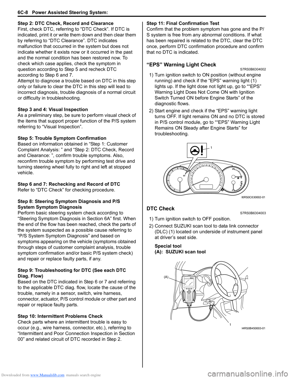
“EPS” Warning Light CheckS7RS0B6304002
1) Turn ignition switch to ON position (without engine
running) and chec k if the “EPS” warning light (1)
lights up. If the light dose not light up, go to ““EPS”
Warning Light Does Not Come ON with Ignition
Switch Turned ON before Engine Starts” of the
diagnostic flows.
2) Start engine and check if the “EPS” warning light turns OFF. If light remains ON and no DTC is stored
in P/S control module, go to ““EPS” Warning Light
Remains ON Steady after Engine Starts” for
troubleshooting.
DTC CheckS7RS0B6304003
1) Turn ignition switch to OFF position.
2) Connect SUZUKI scan tool to data link connector (DLC) (1) located on underside of instrument panel
at driver’s seat side.
Special tool
(A): SUZUKI scan tool
1
I6RS0C630002-01
(A)
1
I4RS0B450003-01
Page 894 of 1496
Downloaded from www.Manualslib.com manuals search engine 6C-12 Power Assisted Steering System:
Scan Tool Data Definitions
Battery Voltage
This parameter indicates battery positive voltage.
TQS Power Supply (Torque Sensor Power Supply, V)
This parameter indicates the power supply voltage which
the P/S control module supplies to the torque sensor.
TQS Main Torque (Torque Sensor Main Torque, N ⋅m)
The torque sensor is installed to detect the steering force
and the steering directio n. It consists of two
potentiometers and the main torque sensor is one of
these.
TQS Sub Torque (Torque Sensor Sub Torque, N ⋅m)
The torque sensor is installed to detect the steering force
and the steering directio n. It consists of two
potentiometers and the sub-torque sensor is one of
these. Its output characteristics are compared with those
of the main torque sensor.
Assist Torque (N ⋅m)
This parameter is an internal parameter of the P/S
control module. It is obtained by computing the torque
sensor input signal. Motor Control (Motor Control Current, A)
Based on the input signal, the P/S control module
determines the assist amount
and controls the current to
the motor suitable for that a ssist amount. This parameter
indicates that control value.
Motor Monitor (Motor Monitor Current, A)
This parameter indicates the actually measured value of
the current flowing to the motor. The motor circuit
condition is diagnosed by co mparing this parameter with
“Motor Control” parameter described previously.
Vehicle Speed (km/h, MPH)
Vehicle speed signal is fed from BCM. P/S control
module determines the amount of power assist based on
this vehicle speed signal and the torque sensor signal.
Engine Speed (rpm)
Engine speed signal is fed from the ECM so that it can
be used for trouble diagnos is of the electric power
steering system.
Motor Volt (V)
This parameter indicates the voltage between motor
terminals.
Ignition switch (ON, OFF)
This parameter indicates the condition of the power
supply through the ignition switch.
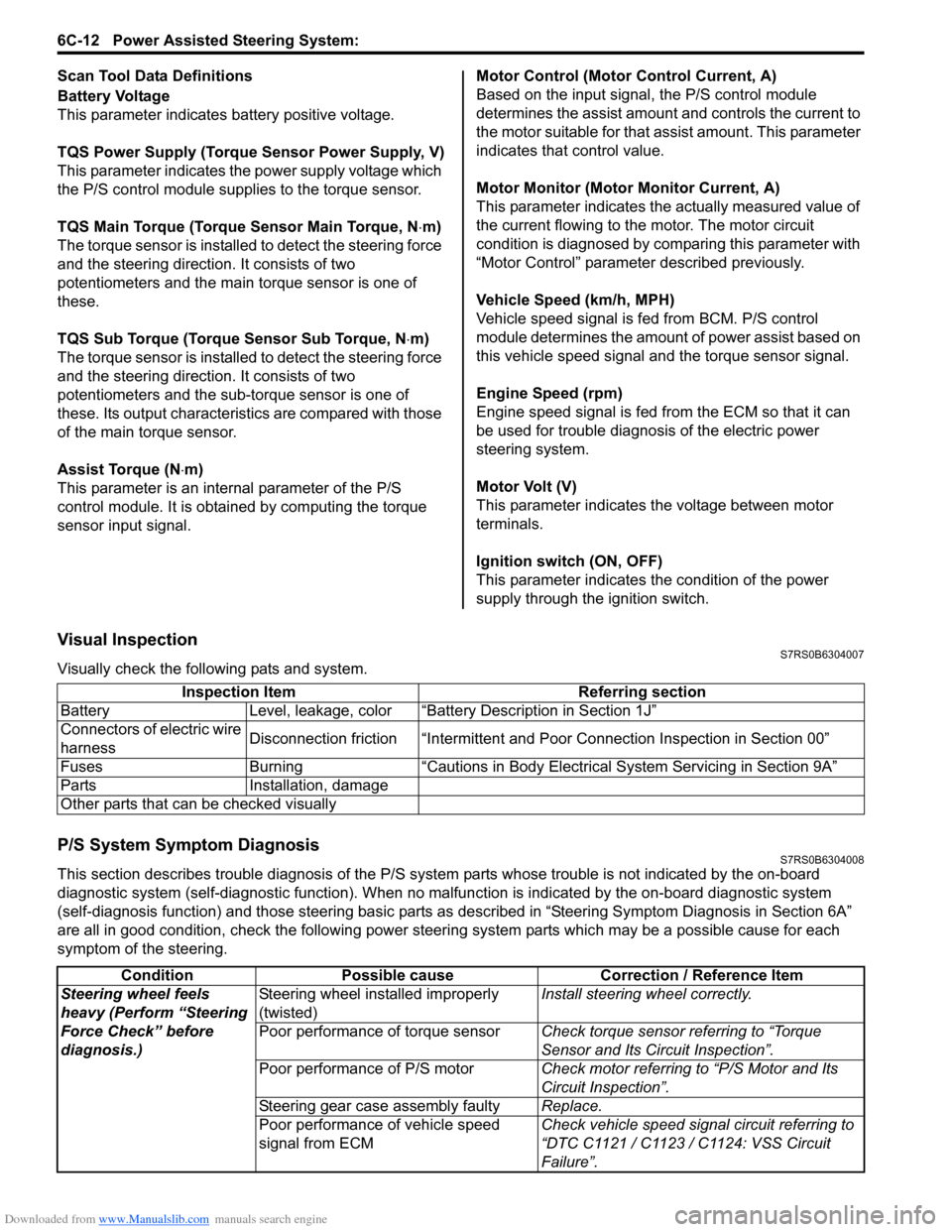
Visual InspectionS7RS0B6304007
Visually check the following pats and system.
P/S System Symptom DiagnosisS7RS0B6304008
This section describes trouble diagnosis of the P/S system parts whose trouble is not indicated by the on-board
diagnostic system (self-diagnostic functi on). When no malfunction is indicated by the on-board diagnostic system
(self-diagnosis function) and those stee ring basic parts as described in “Steering Symptom Diagnosis in Section 6A”
are all in good condition, check the following power steer ing system parts which may be a possible cause for each
symptom of the steering. Inspection Item Referring section
Battery Level, leakage, color “Batte ry Description in Section 1J”
Connectors of electric wire
harness Disconnection friction “Intermittent and Poor
Connection Inspection in Section 00”
Fuses Burning “Cautions in Body Electric al System Servicing in Section 9A”
Parts Installation, damage
Other parts that can be checked visually
Condition Possible cause Correction / Reference Item
Steering wheel feels
heavy (Perform “Steering
Force Check” before
diagnosis.) Steering wheel installed improperly
(twisted)
Install steering wheel correctly.
Poor performance of torque sensor Check torque sensor referring to “Torque
Sensor and Its Circuit Inspection”.
Poor performance of P/S motor Check motor referring to “P/S Motor and Its
Circuit Inspection”.
Steering gear case assembly faulty Replace.
Poor performance of vehicle speed
signal from ECM Check vehicle speed signal circuit referring to
“DTC C1121 / C1123 / C1124: VSS Circuit
Failure”.
Page 895 of 1496
Downloaded from www.Manualslib.com manuals search engine Power Assisted Steering System: 6C-13
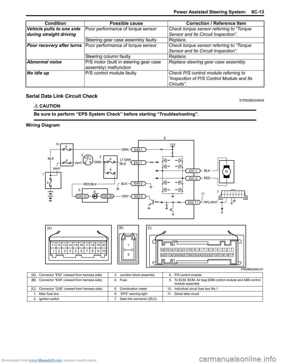
Serial Data Link Circuit CheckS7RS0B6304009
CAUTION!
Be sure to perform “EPS System Check” before starting “Troubleshooting”.
Wiring DiagramVehicle pulls to one side
during straight driving
Poor performance of torque sensor
Check torque sensor referring to “Torque
Sensor and Its Circuit Inspection”.
Steering gear case assembly faulty Replace.
Poor recovery after turns Poor performance of torque sensor Check torque sensor referring to “Torque
Sensor and Its Circuit Inspection”.
Steering column faulty Replace.
Abnormal noise P/S motor (built in steering gear case
assembly) malfunction Replace steering gear case assembly.
No idle up P/S control module faulty Check P/S control module referring to
“Inspection of P/S Control Module and Its
Circuits”.
Condition Possible cause Correction / Reference Item
MBLK
RED
E52-11 E51-1
E51-2PPL/WHT
[A ]
12
3
4 5 67
89
11
10
12 13
141516
17 18 19 2010 9 8 7654 3 21
16 15 14 13 12 11
26 25 24 2322 21 20 19 18 17
32 31 30 29 28 27
[C]
8
79
12V
[B ]
11
12
GRY
LT GRN
/BLK
E52-1
E52-5
E49-1
GRNGRNWHTBLK
WHY
G28-25G28-31
RED/BLK
10
3
4
4
5 6
4
4
1 2
4
E49-2BLK
I7RS0B630003-01
[A]: Connector “E52” (viewed from harness side) 3. Junction block assembly 8. P/S control module
[B]: Connector “E49” (viewed from harness side) 4. Fuse 9. T o ECM, BCM, Air bag SDM control module and ABS control
module assembly
[C]: Connector “G28” (viewed from harness side) 5. Comb ination meter 10. Individual circuit fuse box No.1
1. Main fuse box 6. “EPS” warning light 11. Serial data circuit
2. Ignition switch 7. Date link connector (DLC)
Page 897 of 1496
Downloaded from www.Manualslib.com manuals search engine Power Assisted Steering System: 6C-15
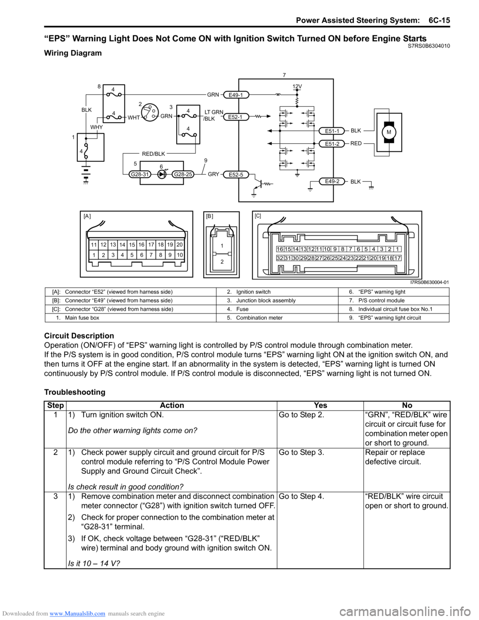
“EPS” Warning Light Does Not Come ON with Ignition Switch Turned ON before Engine StartsS7RS0B6304010
Wiring Diagram
Circuit Description
Operation (ON/OFF) of “EPS” warning light is controlled by P/S control module through combination meter.
If the P/S system is in good condition, P/S control module turns “ EPS” warning light ON at the ignition switch ON, and
then turns it OFF at the engine start. If an abnormality in the system is detected, “EPS” warning light is turned ON
continuously by P/S control module. If P/S control module is disconnected, “EPS” warning light is not turned ON.
Troubleshooting
MBLK
REDE51-1
E51-2
[A ]
12 3
4 5 67
89
11
10
12 13
141516
17 18 19 2010 9 8 7654 3 21
16 15 14 13 12 11
26 25 24 2322 21 20 19 18 17
32 31 30 29 28 27
[C]
7
12V
E49-2BLK
[B ]
1 2
GRY
LT GRN
/BLK
E52-1
E52-5
E49-1
GRNGRNWHTBLK
WHY
G28-25G28-31
RED/BLK
8
3
4
4
5 6
4
4
1 2
4
9
I7RS0B630004-01
[A]: Connector “E52” (viewed from harness side) 2. Ignition switch6. “EPS” warning light
[B]: Connector “E49” (viewed from harness side) 3. Junction block assembly7. P/S control module
[C]: Connector “G28” (viewed from harness si de)4. Fuse 8. Individual circuit fuse box No.1
1. Main fuse box 5. Combination meter9. “EPS” warning light circuit
StepAction YesNo
1 1) Turn ignition switch ON.
Do the other warning lights come on? Go to Step 2.
“GRN”, “RED/BLK” wire
circuit or circuit fuse for
combination meter open
or short to ground.
2 1) Check power supply circuit and ground circuit for P/S control module referring to “P/S Control Module Power
Supply and Ground Circuit Check”.
Is check result in good condition? Go to Step 3.
Repair or replace
defective circuit.
3 1) Remove combination meter and disconnect combination meter connector (“G28”) with ignition switch turned OFF.
2) Check for proper connection to the combination meter at “G28-31” terminal.
3) If OK, check voltage between “G28-31” (“RED/BLK” wire) terminal and body ground with ignition switch ON.
Is it 10 – 14 V? Go to Step 4.
“RED/BLK” wire circuit
open or short to ground.