lock SUZUKI SWIFT 2008 2.G Service Workshop Manual
[x] Cancel search | Manufacturer: SUZUKI, Model Year: 2008, Model line: SWIFT, Model: SUZUKI SWIFT 2008 2.GPages: 1496, PDF Size: 34.44 MB
Page 1231 of 1496
Downloaded from www.Manualslib.com manuals search engine Wiring Systems: 9A-60
1817
GRN/WHTBRN
"E-1"
"E-2"
HVAC
control unit
Auto
unit
G37
Flasher relay Relay
Relay
H
12
"Junction Block
Inner circuit"
J/B (BCM- 12 )J/B (BCM- 18 )
1618
J/B (BCM- 16 )
J/B
"B-5""B-5""B-5""B-5"
11
9
L06
22
10
21
Rear
J/B
GRN
GRN
RED/BLU
RED/BLURED/BLU
RED/BLUGRNRED/BLU
GRN
110
GRN/REDRED/BLURED/BLUBLU/YEL
Rear end
L014
WHT
Rear end
door lock switch
3
"D-5"
BLK/YEL
L01
Luggage compartment light
7
6K01
Interior light
"D-5"
WHT/RED
WR
J/B side connector (BCM)
A
A
A
BY
GWB
W
BYGRRBGGRBGRBGRB
"B-5"
SolenoidMotor (R)
"B-5"
Rear
Motor (L)
"B-3"
HVAC
control unit
BCM
BLK/YEL
BY
BLK/YEL
"D-5"
Solenoid
Rear end
A
A
A
J/C
L74
I7RS0B910918-01
Page 1232 of 1496
Downloaded from www.Manualslib.com manuals search engine 9A-61 Wiring Systems:
50A
3
J/B
15ARADIO
40
2
15A
ACC 1
26
10
1
20AD/L
34
11
10A
METER
25
Main fuse box
WHT
E402
20
Blower motor relay
"Junction Block Inner circuit"
Relay
J/B (BCM- 20 )J/B (BCM- 17 )
17
2L04
9
3
83
B BG33
3
4L05
10
J/C
G15
BLK/ORN
BLK/ORN
16
BLK/ORN
"F-1"
YELPPL/WHT
A/B
SDM
14
316E417G34
Front
position light
"D-2"
"D-2, D-4, G-1"
J/B
RED/YELRED/YEL
J/C
L74D
DD
Licence plate light
"D-2"
YPW
"A-2"
Generator
E464
WHT/BLU
WB
RYRY
RYRYRY
Tail light
(R)
Tail light
(L)
"D-2"
RED/YEL
RED/YEL
RED/YEL
811
C CG37
J/C
G16
YEL
GRYYEL
GY
C
YEL
Y
"G-2"
Multi information
display Auto
unit
"E-2"
A
A
J/C
2E26
+B1
LOCK
ACC
ON
ST ACC IG1 IG2
STOUT
IN
+B2
BLUGRN
G3252
56G21
J/B side connector (BCM)
A
BCM
I7RS0B910919-01
Page 1236 of 1496
Downloaded from www.Manualslib.com manuals search engine 9A-65 Wiring Systems:
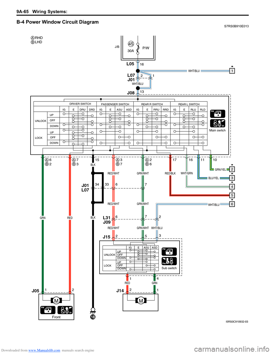
B-4 Power Window Circuit DiagramS7RS0B910E013
12
J15
L31J09
J01
L076
6
34
7
2
7
16
235
1011
1716
1
4
30A
P/W
45
Sub switch Main switch
J1421
GRNRED
RED
15
L05
J/B
18
BLK
BLK
2
13
WHT/BLU
WHT/BLU1
2
3
4
5
6
RED/WHTWHT/BLUGRN/WHT
RED/WHTGRN/WHT
RED/WHTGRN/WHTGRN/YEL
BLU/YEL
RED/BLK
M
GRN
J05
UNLOCK
LOCK
IG
DRIVER SWITCH
PASSENGER SWITCH REAR R SWITCH REAR L SWITCH
E DRU DRD
IG E ASU ASDIG E RLU RLDIG E RRU RRD
WHT/GRN
L07 J01
M
UP
OFF
DOWN
UP OFF
DOWN
J08
UNLOCK UP
OFF
DOWN
UP
OFF
DOWN
LOCK IG E ASU ASD
WHT/BLU
33
1
Front
RHD
LHD
AB
AB6
2AB7
3AB3
7AB2
6
I5RS0C910932-03
Page 1237 of 1496
Downloaded from www.Manualslib.com manuals search engine Wiring Systems: 9A-66
J24L37
J21
J192352 2133
5
L13
J1621 3
5
J23 J18
RED/BLKBLU/YELWHT/BLUGRN/YELWHT/BLUWHT/GRN
4
1211J01
L07
14
21
M
GRNRED
14
21
GRNRED
1
2
3
4
5
6
UNLOCK UP
OFF
DOWN
UP
OFF
DOWN
LOCK IG E RLU RLD
Rear (L)
Sub switch
M
UNLOCK UP
OFF
DOWN
UP
OFF
DOWN
LOCK IG E RRU RRD
WHT/BLU
WHT/BLUWHT/BLUWHT/BLU
GRN/YEL
BLU/YEL
WHT/GRN
RED/BLK
BLU/YELGRN/YELRED/BLKWHT/GRN
Rear (R)
Sub switch
J01
L07
I7RS0B910920-01
Page 1238 of 1496
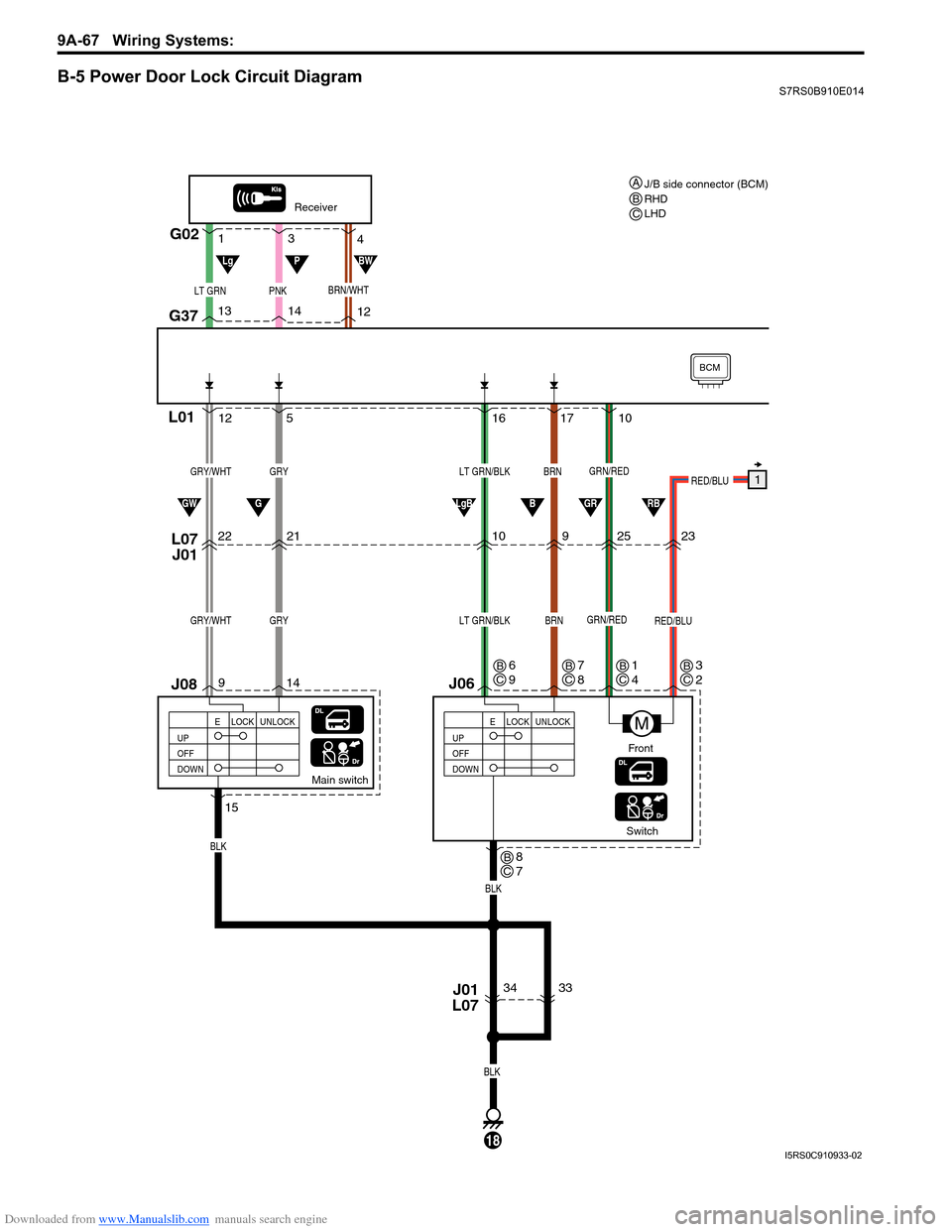
Downloaded from www.Manualslib.com manuals search engine 9A-67 Wiring Systems:
B-5 Power Door Lock Circuit DiagramS7RS0B910E014
17
16
10 9
Switch
J06
L07
J01
BRN
BLK
LT GRN/BLK
Main switch
L01
34
14
9 5
12
22 21
J08
GRY
BLK
BLK
GRY/WHT
BRNLT GRN/BLKGRYGRY/WHT
18
UP
OFF
DOWN LOCK UNLOCK
E
Receiver
G02
G37
LT GRNPNK
14
13
12
3
1
4
UP
OFF
DOWNLOCK UNLOCK
E
J01
L07
15
M
GRN/RED
GRN/RED
BCM
RED/BLU
RED/BLU1
2523
10
GGWLgBBGRRB
LgPBW
Front
BRN/WHT
33
J/B side connector (BCM)
RHD
LHD
ABC
C
B6
9
CB8
7
CB7
8CB1
4CB3
2
I5RS0C910933-02
Page 1242 of 1496
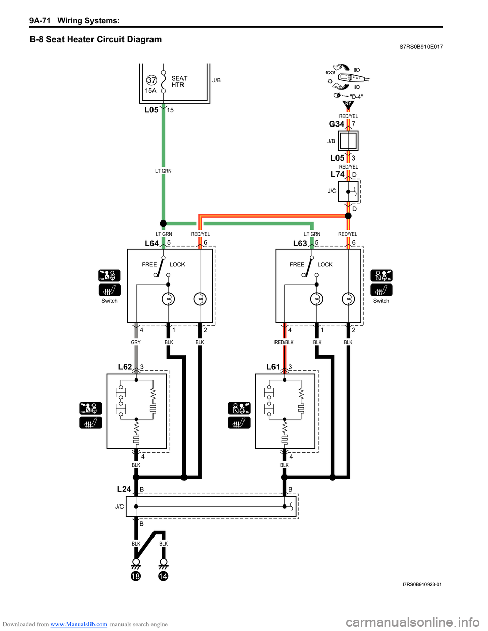
Downloaded from www.Manualslib.com manuals search engine 9A-71 Wiring Systems:
B-8 Seat Heater Circuit DiagramS7RS0B910E017
LT GRN
LT GRNLT GRNRED/YEL
RED/YEL
RED/YEL
RED/YEL
GRYBLK
L6456
L623
4
4
12
L635
18
L613
4
BLKRED/BLKBLK
412
BLK
BLK
BLK
14
BLK
BLK
Switch FREE LOCK FREE LOCKSwitch
L0515
15A
SEAT
HTR37J/B
6
RY"D-4"
7
3
J/B
G34 L05
B
BB
J/C
L24
D D
J/C
L74
I7RS0B910923-01
Page 1243 of 1496
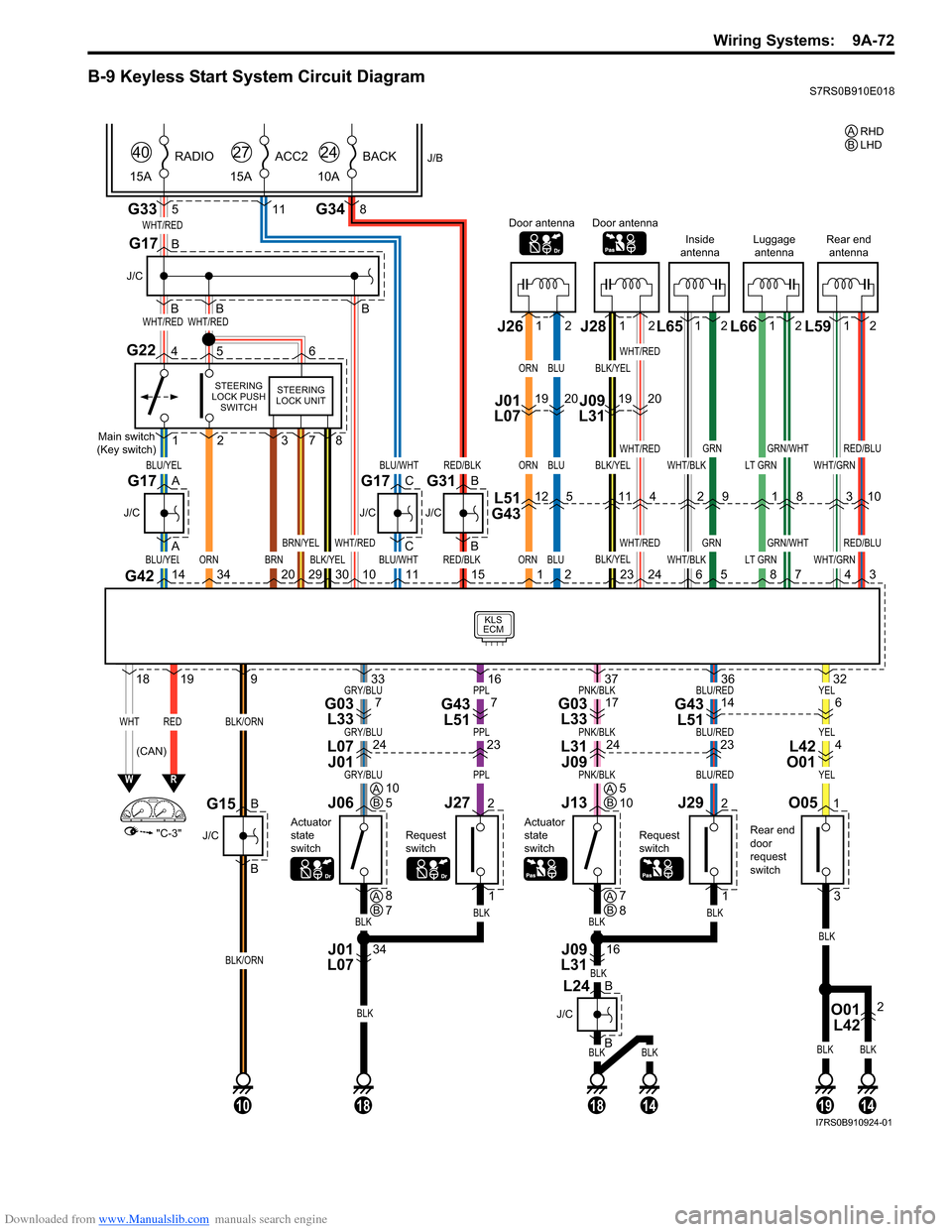
Downloaded from www.Manualslib.com manuals search engine Wiring Systems: 9A-72
B-9 Keyless Start System Circuit DiagramS7RS0B910E018
BLKBLK
BLK
BLKBLK
YELBLU/REDPNK/BLKPPLGRY/BLU
YELBLU/REDPNK/BLKPPLGRY/BLU
YELBLU/REDPNK/BLKPPLGRY/BLU
G33
KLS
ECM
WHT/RED
WHT/REDWHT/RED
BLU/YEL
WHTRED
ORN
BLU/YEL
"C-3"
WR
G42143420
1819
BLK/ORN
BLK/ORN
9
5
J/B
15A RADIO
40
G348
10A
BACK
24
11
15A
ACC2
27
B
B
B
J/C
G17
B
A
A
J/C
BLU/WHT
BLU/WHT
C
C
J/C
G17
Main switch
(Key switch)
STEERING
LOCK PUSH SWITCH
G22456
1
O051
3
2
BRN29
BRN/YEL
301011RED/BLK
RED/BLK
B
B
J/C
Rear end
door
request
switch
G31
15ORN
ORN
ORN
1BLK/YEL
WHT/RED
378
STEERING
LOCK UNIT
Door antenna
L51
G4312
J01
L07 J261912
BLU
BLU
BLU
2
5
20
WHT/BLK
WHT/BLK6
Inside
antenna
2
12
GRN
GRN
5
9
LT GRN
LT GRN8
Luggage antenna
1
12
GRN/WHT
GRN/WHT
7
8
BLK/YEL
BLK/YEL
BLK/YEL
23
Door antenna
11
J09
L31 J28 L65 L66
WHT/GRN
WHT/GRN4
Rear end
antenna
3
12
RED/BLU
RED/BLU
3
10
L59
1912
WHT/RED
WHT/RED
WHT/RED
24
4
20
G17
B
B
J/C
G15
10
BLK
BLKBLK
32
J292
1
Request
switch
36
1914
J13
Actuator
state
switch
O01 L422
16
BLK
37
1814
J09
L31
J272
1
Request
switch
16
J06
Actuator
state
switch
34
BLK
BLK
33
18
J01
L07
(CAN) RHD
A
LHD
B
AB10
5AB5
10
AB8
7AB7
8
614G43
L5117G03 L337G43 L517G03 L33
423242324L42
O01
L31
J09
L07
J01
B
J/C
B
L24
I7RS0B910924-01
Page 1266 of 1496
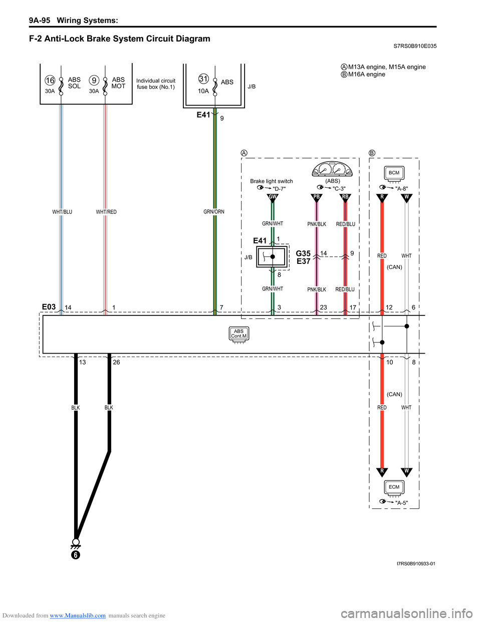
Downloaded from www.Manualslib.com manuals search engine 9A-95 Wiring Systems:
F-2 Anti-Lock Brake System Circuit DiagramS7RS0B910E035
1326
14
1 3
23
17
E03
ABS
Cont.M
BCM
BLK
30A
ABS
SOL16
30A
ABS
MOT9
WHT/REDWHT/BLU
GRN/WHT
6
BLKREDWHT
PNK/BLK
PB
PNK/BLK
RB
RED/BLU
RED/BLU
149G35 E37
"C-3""A-8"
ECM
"A-5"
J/B10A ABS
31
E419
GRN/ORN
7
GW"D-7"Brake light switch
(CAN)
(CAN)
(ABS)
GRN/WHT
J/B
E411
8
Individual circuit fuse box (No.1)
108
12
RED
R
6
WHT
W
RW
M13A engine, M15A engine
M16A engineA
AB
B
I7RS0B910933-01
Page 1283 of 1496
Downloaded from www.Manualslib.com manuals search engine Lighting Systems: 9B-1
Body, Cab and Accessories
Lighting Systems
Component Location
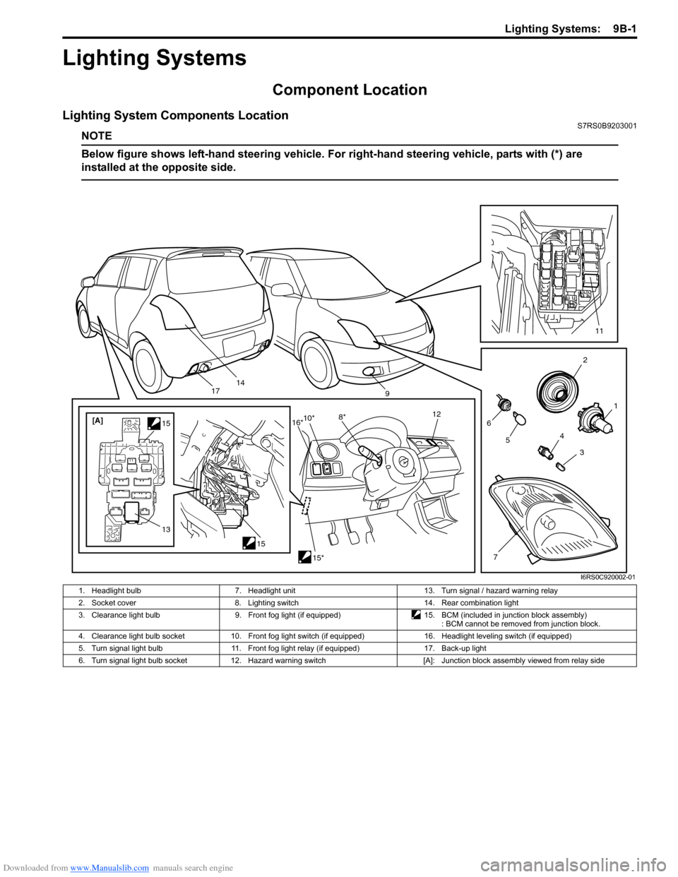
Lighting System Components LocationS7RS0B9203001
NOTE
Below figure shows left-hand steering vehicle. For right-hand steering vehicle, parts with (*) are
installed at the opposite side.
2
1
3
4
6
14
5
7
11
9
15
[A]
1515*
10*
8* 12
13
16*
17
I6RS0C920002-01
1. Headlight bulb 7. Headlight unit 13. Turn signal / hazard warning relay
2. Socket cover 8. Lighting switch 14. Rear combination light
3. Clearance light bulb 9. Front fog light (if equipped)15. BCM (included in junction block assembly)
: BCM cannot be removed from junction block.
4. Clearance light bulb socket 10. Front fog light switch (if equipped) 16. Headlight leveling switch (if equipped)
5. Turn signal light bulb 11. Front fog light relay (if equipped) 17. Back-up light
6. Turn signal light bulb socket 12. Hazard warning switch [A]: Junction block assembly viewed from relay side
Page 1284 of 1496
Downloaded from www.Manualslib.com manuals search engine 9B-2 Lighting Systems:
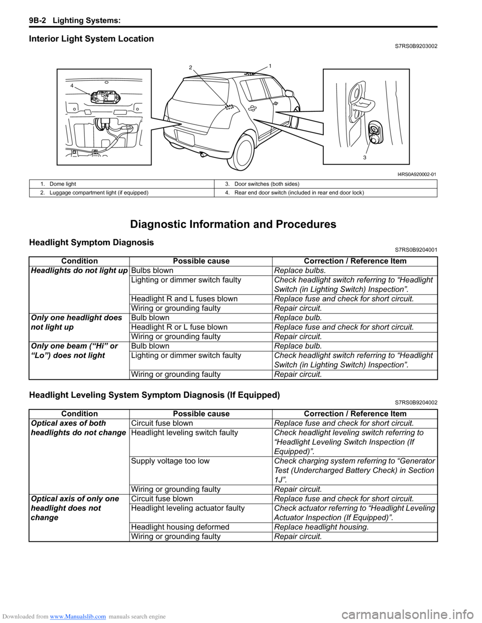
Interior Light System LocationS7RS0B9203002
Diagnostic Information and Procedures
Headlight Symptom DiagnosisS7RS0B9204001
Headlight Leveling System Symptom Diagnosis (If Equipped)S7RS0B9204002
13
2
4
I4RS0A920002-01
1. Dome light 3. Door switches (both sides)
2. Luggage compartment light (if equipped) 4. Rear end door switch (included in rear end door lock)
ConditionPossible cause Correction / Reference Item
Headlights do not light up Bulbs blown Replace bulbs.
Lighting or dimmer switch faulty Check headlight switch referring to “Headlight
Switch (in Lighting Switch) Inspection”.
Headlight R and L fuses blown Replace fuse and check for short circuit.
Wiring or grounding faulty Repair circuit.
Only one headlight does
not light up Bulb blown
Replace bulb.
Headlight R or L fuse blown Replace fuse and check for short circuit.
Wiring or grounding faulty Repair circuit.
Only one beam (“Hi” or
“Lo”) does not light Bulb blown
Replace bulb.
Lighting or dimmer switch faulty Check headlight switch referring to “Headlight
Switch (in Lighting Switch) Inspection”.
Wiring or grounding faulty Repair circuit.
ConditionPossible cause Correction / Reference Item
Optical axes of both
headlights do not change Circuit fuse blown
Replace fuse and check for short circuit.
Headlight leveling switch faulty Check headlight leveling switch referring to
“Headlight Leveling Switch Inspection (If
Equipped)”.
Supply voltage too low Check charging system referring to “Generator
Test (Undercharged Battery Check) in Section
1J”.
Wiring or grounding faulty Repair circuit.
Optical axis of only one
headlight does not
change Circuit fuse blown
Replace fuse and check for short circuit.
Headlight leveling actuator faulty Check actuator referring to “Headlight Leveling
Actuator Inspection (If Equipped)”.
Headlight housing deformed Replace headlight housing.
Wiring or grounding faulty Repair circuit.