diagnosis SUZUKI SWIFT 2008 2.G Service Workshop Manual
[x] Cancel search | Manufacturer: SUZUKI, Model Year: 2008, Model line: SWIFT, Model: SUZUKI SWIFT 2008 2.GPages: 1496, PDF Size: 34.44 MB
Page 1077 of 1496
Downloaded from www.Manualslib.com manuals search engine Air Bag System: 8B-39
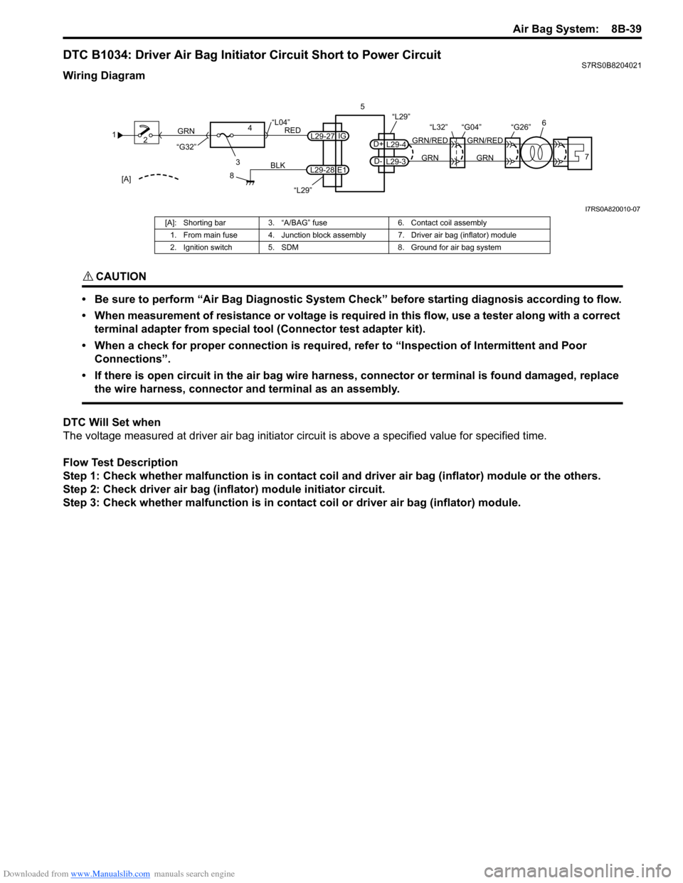
DTC B1034: Driver Air Bag Initiator Circuit Short to Power CircuitS7RS0B8204021
Wiring Diagram
CAUTION!
• Be sure to perform “Air Bag Diagnostic System Check” before starting diagnosis according to flow.
• When measurement of resistance or voltage is required in this flow, use a tester along with a correct terminal adapter from special tool (Connector test adapter kit).
• When a check for proper connection is required, refer to “Inspection of Intermittent and Poor Connections”.
• If there is open circuit in the air bag wire harnes s, connector or terminal is found damaged, replace
the wire harness, connector and terminal as an assembly.
DTC Will Set when
The voltage measured at driver air bag initiator ci rcuit is above a specified value for specified time.
Flow Test Description
Step 1: Check whether malfunction is in contact coil and driver air bag (inflator) module or the others.
Step 2: Check driver air bag (inflator) module initiator circuit.
Step 3: Check whether malfunction is in contact coil or driver air bag (inflator) module.
1 2
3
GRN
RED
8
BLK
L29-27
L29-28 IG
E1
4
“L29”
“L04”
“G32”
“L29”
L29-4
D+
L29-3
D-GRN
GRN/RED
GRN
GRN/RED 6
57
“G26”
“L32” “G04”
[A]
I7RS0A820010-07
[A]: Shorting bar 3. “A/BAG” fuse 6. Contact coil assembly
1. From main fuse 4. Junction block assembly 7. Driver air bag (inflator) module
2. Ignition switch 5. SDM 8. Ground for air bag system
Page 1082 of 1496

Downloaded from www.Manualslib.com manuals search engine 8B-44 Air Bag System:
DTC B1041: Passenger Air Bag Initiator Circuit Resistance HighS7RS0B8204022
Wiring Diagram
CAUTION!
• Be sure to perform “Air Bag Diagnostic System Check” before starting diagnosis according to flow.
• When measurement of resistance or voltage is required in this flow, use a tester along with a correct terminal adaptor from special tool (Connector test adapter kit).
• When a check for proper connection is required, refer to “Inspection of Intermittent and Poor Connections”.
• If there is open circuit in the air bag wire harnes s, connector or terminal is found damaged, replace
the wire harness, connector and terminal as an assembly.
DTC Will Set when
The combined resistance of the passenger air bag (inflator) module, harness wiring and connector terminal contact is
above a specified value for specified time.
Flow Test Description
Step 1: Check if malfunction is in passenger air bag (inflator) module.
Step 2: Check passenger air bag (inflator) module initiator circuit. (in instrument panel harness)
Step 3: Check passenger air bag (inflator) module initiator circuit. (in floor harness)
1
2
3
GRN
RED
7
BLK
L29-27
L29-28 IG
E1
4
“L29”
“L04”
“G32”
“L29”
L29-5
P+
L29-6
P-YEL/RED
BLU/RED
YEL/RED
BLU/RED
56
“L32” “G04”
“G10”
[A]
I7RS0A820013-06
[A]: Shorting bar 3. “A/BAG” fuse
6. Passenger air bag (inflator) module
1. From main fuse 4. Junction block assembly 7. Ground for air bag system
2. Ignition switch 5. SDM
Page 1086 of 1496

Downloaded from www.Manualslib.com manuals search engine 8B-48 Air Bag System:
CAUTION!
• Be sure to perform “Air Bag Diagnostic System Check” before starting diagnosis according to flow.
• When measurement of resistance or voltage is required in this flow, use a tester along with a correct terminal adaptor from special tool (Connector test adapter kit).
• When a check for proper connection is required, refer to “Inspection of Intermittent and Poor Connections”.
• If there is open circuit in the air bag wire harnes s, connector or terminal is found damaged, replace
the wire harness, connector and terminal as an assembly.
DTC Will Set when
The combined resistance of the passenger air bag (inflator) module, harness wiring and connector terminal contact is
below a specified value for specified time.
Flow Test Description
Step 1: Check if malfunction is in passenger air bag (inflator) module.
Step 2: Check passenger air bag (inflator) module initiator circuit. (in instrument panel harness)
Step 3: Check passenger air bag (inflator) module initiator circuit. (in floor harness)
DTC Troubleshooting Step Action YesNo
1 1) With ignition switch OFF, disconnect passenger air bag (inflator) module connector.
2) Check proper connection to passenger air bag (inflator) module at terminals in “G10” connector.
3) If OK, then connect special tools (A), (B) and (D) to “G10” connector.
Special tool
(A): 09932–76010
(B): 09932–75010
(D): 09932–78310
4) Check SDM DTC.
With ignition switch ON , is DTC B1042 indicated? Go to Step 2.
Turn ignition switch
OFF. Replace
passenger air bag
(inflator) module
referring to “Passenger
Air Bag (Inflator) Module
Removal and
Installation”.
STEERING WHEEL(B)
(D)
(A)
"G10"
I4RS0A820021-01
Page 1089 of 1496

Downloaded from www.Manualslib.com manuals search engine Air Bag System: 8B-51
CAUTION!
• Be sure to perform “Air Bag Diagnostic System Check” before starting diagnosis according to flow.
• When measurement of resistance or voltage is required in this flow, use a tester along with a correct terminal adaptor from special tool (Connector test adapter kit).
• When a check for proper connection is required, refer to “Inspection of Intermittent and Poor Connections”.
• If there is open circuit in the air bag wire harnes s, connector or terminal is found damaged, replace
the wire harness, connector and terminal as an assembly.
DTC Will Set when
The voltage measured at passenger air bag (initiator) circuit is below a specified value for specified time.
Flow Test Description
Step 1: Check if malfunction is in passenger air bag (inflator) module.
Step 2: Check passenger air bag (inflator) module initiator circuit. (in instrument panel harness)
Step 3: Check passenger air bag (inflator) module initiator circuit. (in floor harness)
DTC Troubleshooting Step Action YesNo
1 1) With ignition switch OFF, disconnect passenger air bag (inflator) module connector.
2) Check proper connection to passenger air bag (inflator) module at terminals in “G10” connector.
3) If OK, then connect special tools (A), (B) and (D) to “G10” connector.
Special tool
(A): 09932–76010
(B): 09932–75010
(D): 09932–78310
4) Check SDM DTC.
With ignition switch ON , is DTC B1043 indicated? Go to Step 2.
Turn ignition switch
OFF. Replace
passenger air bag
(inflator) module
referring to “Passenger
Air Bag (Inflator) Module
Removal and
Installation”.
STEERING WHEEL(B)
(D)
(A)
"G10"
I4RS0A820021-01
Page 1092 of 1496

Downloaded from www.Manualslib.com manuals search engine 8B-54 Air Bag System:
CAUTION!
• Be sure to perform “Air Bag Diagnostic System Check” before starting diagnosis according to flow.
• When measurement of resistance or voltage is required in this flow, use a tester along with a correct terminal adaptor from special tool (Connector test adapter kit).
• When a check for proper connection is required, refer to “Inspection of Intermittent and Poor Connections”.
• If there is open circuit in the air bag wire harnes s, connector or terminal is found damaged, replace
the wire harness, connector and terminal as an assembly.
DTC Will Set when
The voltage measured at passenger air bag (initiator) circuit is above a specified value for specified time.
Flow Test Description
Step 1: Check if malfunction is in passenger air bag (inflator) module.
Step 2: Check passenger air bag (inflator) module initiator circuit. (in instrument panel harness)
Step 3: Check passenger air bag (inflator) module initiator circuit. (in floor harness)
DTC Troubleshooting Step Action YesNo
1 1) With ignition switch OFF, disconnect passenger air bag (inflator) module connector.
2) Check proper connection to passenger air bag (inflator) module at terminals in “G10” connector.
3) If OK, then connect special tools (A), (B) and (D) to “G10” connector.
Special tool
(A): 09932–76010
(B): 09932–75010
(D): 09932–78310
4) Check SDM DTC.
With ignition switch ON , is DTC B1044 indicated? Go to Step 3.
Turn ignition switch
OFF. Replace
passenger air bag
(inflator) module
referring to “Passenger
Air Bag (Inflator) Module
Removal and
Installation”.
STEERING WHEEL(B)
(D)
(A)
"G10"
I4RS0A820021-01
Page 1095 of 1496
Downloaded from www.Manualslib.com manuals search engine Air Bag System: 8B-57
CAUTION!
• Be sure to perform “Air Bag Diagnostic System Check” before starting diagnosis according to flow.
• When measurement of resistance or voltage is required in this flow, use a tester along with a correct terminal adapter from special tool (Connector test adapter kit).
• When a check for proper connection is required, refer to “Inspection of Intermittent and Poor Connections”.
• If there is open circuit in the air bag wire harnes s, connector or terminal is found damaged, replace
the wire harness, connector and terminal as an assembly.
DTC Will Set when
The resistance of driver or passenger seat belt pretensioner initiator circuit is above a specified value for specified
time.
Flow Test Description
Step 1: Check if malfunction is in seat belt pretensioner.
Step 2: Check seat belt pretensioner initiator circuit.
DTC Troubleshooting
Step Action YesNo
1 1) With ignition switch OFF, re move center pillar lower trim
of driver or passenger side and disconnect seat belt
pretensioner connector “L10” or “L36” (1).
2) Check proper connection to seat belt pretensioner at terminals in “L10” or “L36” connector.
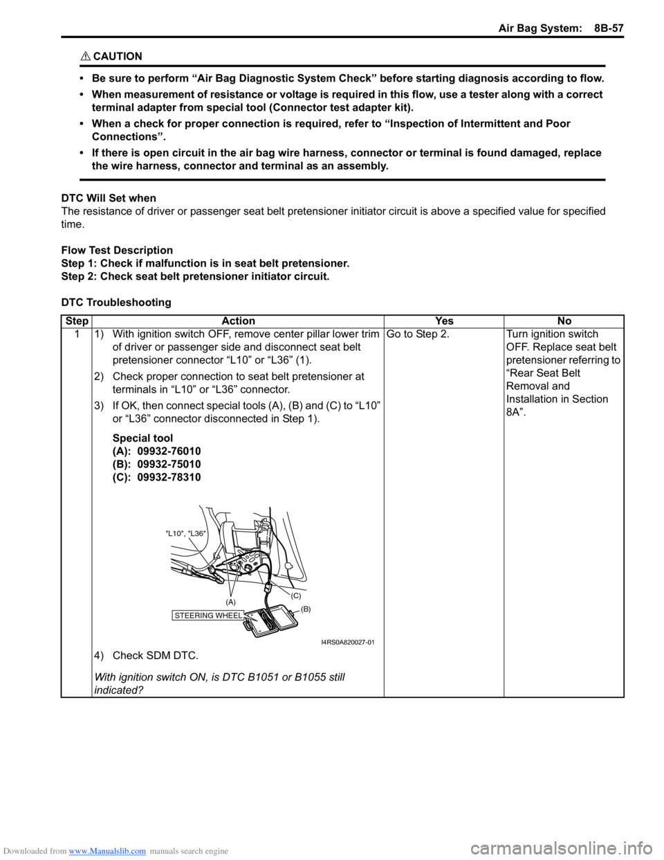
3) If OK, then connect special tools (A), (B) and (C) to “L10” or “L36” connector disconnected in Step 1).
Special tool
(A): 09932-76010
(B): 09932-75010
(C): 09932-78310
4) Check SDM DTC.
With ignition switch ON, is DTC B1051 or B1055 still
indicated? Go to Step 2.
Turn ignition switch
OFF. Replace seat belt
pretensioner referring to
“Rear Seat Belt
Removal and
Installation in Section
8A”.
STEERING WHEEL(B)
(C)
(A)
"L10", "L36"
I4RS0A820027-01
Page 1097 of 1496
Downloaded from www.Manualslib.com manuals search engine Air Bag System: 8B-59
CAUTION!
• Be sure to perform “Air Bag Diagnostic System Check” before starting diagnosis according to flow.
• When measurement of resistance or voltage is required in this flow, use a tester along with a correct terminal adapter from special tool (Connector test adapter kit).
• When a check for proper connection is required, refer to “Inspection of Intermittent and Poor Connections”.
• If there is open circuit in the air bag wire harnes s, connector or terminal is found damaged, replace
the wire harness, connector and terminal as an assembly.
DTC Will Set when
The resistance of driver or passenger seat belt pretensioner initiator circuit is below a specified value for specified
time.
Flow Test Description
Step 1: Check if malfunction is in seat belt pretensioner.
Step 2: Check seat belt pretensioner initiator circuit.
DTC Troubleshooting
Step Action YesNo
1 1) With ignition switch OFF, re move center pillar lower trim
of driver or passenger side and disconnect seat belt
pretensioner connector “L10” or “L36” (1).
2) Check proper connection to seat belt pretensioner at terminals in “L10” or “L36” connector.
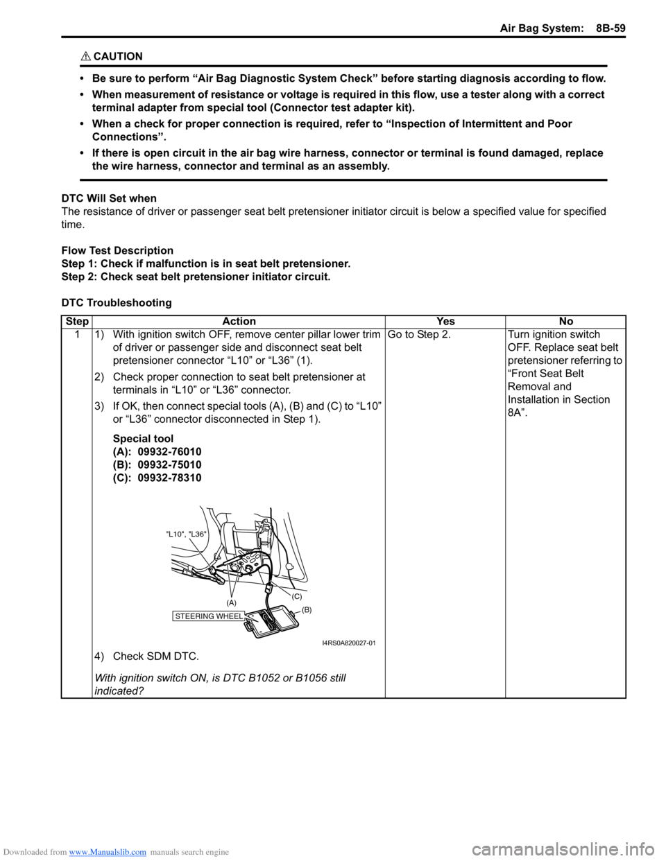
3) If OK, then connect special tools (A), (B) and (C) to “L10” or “L36” connector disconnected in Step 1).
Special tool
(A): 09932-76010
(B): 09932-75010
(C): 09932-78310
4) Check SDM DTC.
With ignition switch ON, is DTC B1052 or B1056 still
indicated? Go to Step 2.
Turn ignition switch
OFF. Replace seat belt
pretensioner referring to
“Front Seat Belt
Removal and
Installation in Section
8A”.
STEERING WHEEL(B)
(C)
(A)
"L10", "L36"
I4RS0A820027-01
Page 1099 of 1496
Downloaded from www.Manualslib.com manuals search engine Air Bag System: 8B-61
CAUTION!
• Be sure to perform “Air Bag Diagnostic System Check” before starting diagnosis according to flow.
• When measurement of resistance or voltage is required in this flow, use a tester along with a correct terminal adapter from special tool (Connector test adapter kit).
• When a check for proper connection is required, refer to “Inspection of Intermittent and Poor Connections”.
• If there is open circuit in the air bag wire harnes s, connector or terminal is found damaged, replace
the wire harness, connector and terminal as an assembly.
DTC Will Set when
The voltage measured at driver or passenger seat belt pr etensioner initiator circuit is below a specified value for
specified time.
Flow Test Description
Step 1: Check if malfunction is in seat belt pretensioner.
Step 2: Check seat belt pretensioner initiator circuit.
DTC Troubleshooting
Step Action YesNo
1 1) With ignition switch OFF, re move center pillar lower trim
of driver or passenger side and disconnect seat belt
pretensioner connector “L10” or “L36” (1).
2) Check proper connection to seat belt pretensioner at terminals in “L10” or “L36” connector.
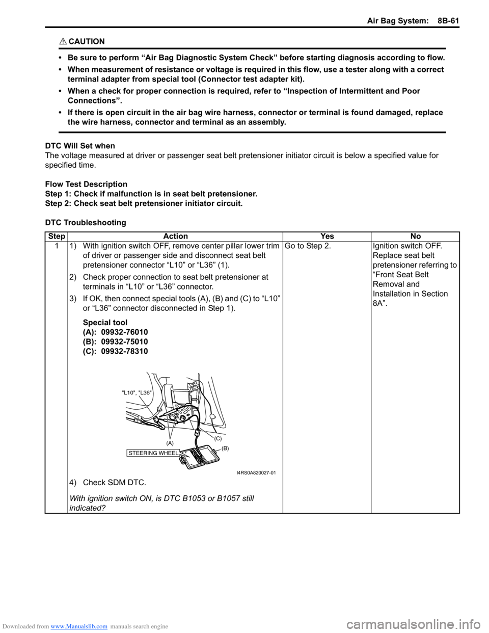
3) If OK, then connect special tools (A), (B) and (C) to “L10” or “L36” connector disconnected in Step 1).
Special tool
(A): 09932-76010
(B): 09932-75010
(C): 09932-78310
4) Check SDM DTC.
With ignition switch ON, is DTC B1053 or B1057 still
indicated? Go to Step 2.
Ignition switch OFF.
Replace seat belt
pretensioner referring to
“Front Seat Belt
Removal and
Installation in Section
8A”.
STEERING WHEEL(B)
(C)
(A)
"L10", "L36"
I4RS0A820027-01
Page 1101 of 1496
Downloaded from www.Manualslib.com manuals search engine Air Bag System: 8B-63
CAUTION!
• Be sure to perform “Air Bag Diagnostic System Check” before starting diagnosis according to flow.
• When measurement of resistance or voltage is required in this flow, use a tester along with a correct terminal adapter from special tool (Connector test adapter kit).
• When a check for proper connection is required, refer to “Inspection of Intermittent and Poor Connections”.
• If there is open circuit in the air bag wire harnes s, connector or terminal is found damaged, replace
the wire harness, connector and terminal as an assembly.
DTC Will Set when
The voltage measured at driver or passenger seat belt pr etensioner initiator circuit is above a specified value for
specified time.
Flow Test Description
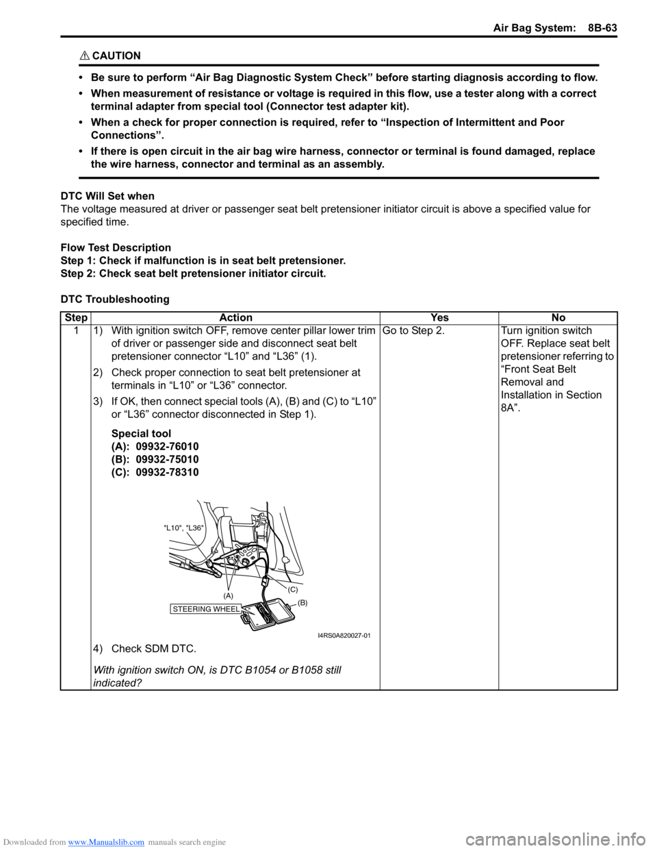
Step 1: Check if malfunction is in seat belt pretensioner.
Step 2: Check seat belt pretensioner initiator circuit.
DTC Troubleshooting
Step Action YesNo
1 1) With ignition switch OFF, re move center pillar lower trim
of driver or passenger side and disconnect seat belt
pretensioner connector “L10” and “L36” (1).
2) Check proper connection to seat belt pretensioner at terminals in “L10” or “L36” connector.
3) If OK, then connect special tools (A), (B) and (C) to “L10” or “L36” connector disconnected in Step 1).
Special tool
(A): 09932-76010
(B): 09932-75010
(C): 09932-78310
4) Check SDM DTC.
With ignition switch ON, is DTC B1054 or B1058 still
indicated? Go to Step 2.
Turn ignition switch
OFF. Replace seat belt
pretensioner referring to
“Front Seat Belt
Removal and
Installation in Section
8A”.
STEERING WHEEL(B)
(C)
(A)
"L10", "L36"
I4RS0A820027-01
Page 1103 of 1496
Downloaded from www.Manualslib.com manuals search engine Air Bag System: 8B-65
CAUTION!
• Be sure to perform “Air Bag Diagnostic System Check” before starting diagnosis according to flow.
• When measurement of resistance or voltage is required in this flow, use a tester along with a correct terminal adapter from special tool (Connector test adapter kit).
• When a check for proper connection is required, refer to “Inspection of Intermittent and Poor Connections”.
• If there is open circuit in the air bag wire harnes s, connector or terminal is found damaged, replace
the wire harness, connector and terminal as an assembly.
DTC Will Set when
The combined resistance of the side-air bag (inflator) module (driver or passenger), harness wiring and connector
terminal contact is above a spec ified value for specified time.
Flow Test Description
Step 1: Check whether malfunction is in side-air bag (inflator) module.
Step 2: Check side-air bag initiator circuit in floor harness.
Step 3: Check side-air bag init iator circuit in seat harness.
DTC Troubleshooting Step Action YesNo
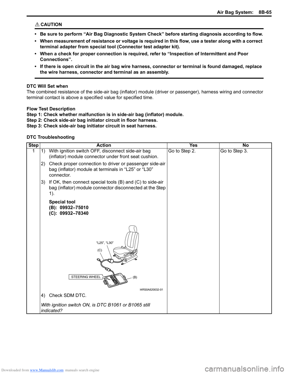
1 1) With ignition switch OFF, disconnect side-air bag (inflator) module connector under front seat cushion.
2) Check proper connection to driver or passenger side-air bag (inflator) module at terminals in “L25” or “L30”
connector.
3) If OK, then connect special tools (B) and (C) to side-air bag (inflator) module connector disconnected at the Step
1).
Special tool
(B): 09932–75010
(C): 09932–78340
4) Check SDM DTC.
With ignition switch ON, is DTC B1061 or B1065 still
indicated? Go to Step 2.
Go to Step 3.
“L25”, “L30”
(C)
(B)
STEERING WHEEL
I4RS0A820032-01