1-1 SUZUKI SWIFT 2008 2.G Service Owner's Guide
[x] Cancel search | Manufacturer: SUZUKI, Model Year: 2008, Model line: SWIFT, Model: SUZUKI SWIFT 2008 2.GPages: 1496, PDF Size: 34.44 MB
Page 1016 of 1496
Downloaded from www.Manualslib.com manuals search engine 7B-68 Air Conditioning System: Automatic Type
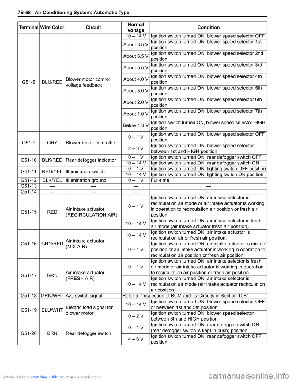
G51-8 BLU/REDBlower motor control
voltage feedback 10 – 14 V Ignition switch turned ON, blower speed selector OFF
About 8.5 V Ignition switch turned ON, blower speed selector 1st
position
About 6.5 V Ignition switch turned ON, blower speed selector 2nd
position
About 5.5 V Ignition switch turned ON, blower speed selector 3rd
position
About 4.0 V Ignition switch turned ON, blower speed selector 4th
position
About 3.0 V Ignition switch turned ON, blower speed selector 5th
position
About 2.0 V Ignition switch turned ON, blower speed selector 6th
position
About 1.0 V Ignition switch turned ON, blower speed selector 7th
position
Below 1.0 V Ignition switch turned ON, blower speed selector HIGH
position
G51-9 GRY Blower motor controller 0 – 1 V
Ignition switch turned ON, blower speed selector OFF
position
2 – 3 V Ignition switch turned ON, blower speed selector
between 1st and HIGH position
G51-10 BLK/RED Rear defogger indicator 0 – 1 V Ignition switch turned ON, rear defogger switch OFF
10 – 14 V Ignition switch turned ON, rear defogger switch ON
G51-11 RED/YEL Illumination switch 0 – 1 V Ignition switch turned ON, lighting switch OFF position
10 – 14 V Ignition switch turned ON, lighting switch ON position
G51-12 BLK/YEL Illumination ground 0 – 1 V Full-time
G51-13 — — — —
G51-14 — — — —
G51-15 RED Air intake actuator
(RECIRCULATION AIR) 0 – 1 VIgnition switch turned ON, air intake selector is
recirculation air mode or air intake actuator is working
in operation to recirculation air position or fresh air
position.
10 – 14 V Ignition switch turned ON, ai
r intake selector is fresh
air mode (air intake actuator fresh air position).
G51-16 GRN/RED Air intake actuator
(MIX AIR) 10 – 14 V
Ignition switch turned ON, air intake actuator is
recirculation air or fresh air position.
0 – 1 V Ignition switch turned ON, air intake actuator is mix air
position or air intake actuator is working in operation to
recirculation air position or fresh air position.
G51-17 GRN Air intake actuator
(FRESH AIR) 0 – 1 V
Ignition switch turned ON, ai
r intake selector is fresh
air mode or air intake actuator is working in operation
to recirculation air position or fresh air position.
10 – 14 V Ignition switch turned ON, air intake selector is
recirculation air mode (air intake actuator recirculation
air position).
G51-18 GRN/WHT A/C switch signal Refer to “Inspe ction of BCM and its Circuits in Section 10B”
G51-19 BLU/WHT Electric load signal for
blower motor 10 – 14 V
Ignition switch turned ON, blower speed selector OFF
or between 1st and 5th position
0 – 2 V Ignition switch turned ON, blower speed selector
between 6th and HIGH position
G51-20 BRN Rear defogger switch 0 – 1 V
Ignition switch turned ON, rear defogger switch ON
(rear defogger switch is kept in push) position
4 – 6 V Ignition switch turned ON, rear defogger switch OFF
position
Terminal Wire Color Circuit
Normal
Vo l ta g e Condition
Page 1120 of 1496
Downloaded from www.Manualslib.com manuals search engine 8B-82 Air Bag System:
CAUTION!
• Be sure to perform “Air Bag Diagnostic System Check” before starting diagnosis according to flow.
• When measurement of resistance or voltage is required in this flow, use a tester along with a correct terminal adapter from special tool (Connector test adapter kit).
• When a check for proper connection is required, refer to “Inspection of Intermittent and Poor Connections”.
• If there is open circuit in the air bag wire harnes s, connector or terminal is found damaged, replace
the wire harness, connector and terminal as an assembly.
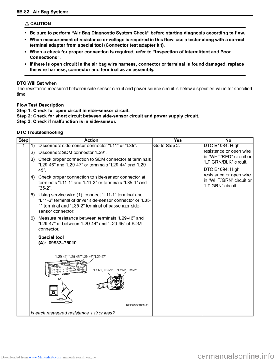
DTC Will Set when
The resistance measured between side-sensor circuit and power source circuit is below a specified value for specified
time.
Flow Test Description
Step 1: Check for open circuit in side-sensor circuit.
Step 2: Check for short circuit between side-sensor circuit and power supply circuit.
Step 3: Check if malfunction is in side-sensor.
DTC Troubleshooting
Step Action YesNo
1 1) Disconnect side-sensor connector “L11” or “L35”.
2) Disconnect SDM connector “L29”.
3) Check proper connection to SDM connector at terminals “L29-46” and “L29-47” or terminals “L29-44” and “L29-
45”.
4) Check proper connection to side-sensor connector at terminals “L11-1” and “L11-2” or terminals “L35-1” and
“35-2”.
5) Using service wire (1), connect “L11-1” terminal and “L11-2” terminal of driver side-sensor connector or “L35-
1” terminal and “L35-2” terminal of passenger side-
sensor connector.
6) Measure resistance between terminals “L29-46” and “L29-47” or between “L29-44” and “L29-45” of SDM
connector.
Special tool
(A): 09932–76010
Is each measured resistance 1
Ω or less? Go to Step 2. DTC B1084: High
resistance or open wire
in “WHT/RED” circuit or
“LT GRN/BLK” circuit.
DTC B1094: High
resistance or open wire
in “WHT/GRN” circuit or
“LT GRN” circuit.
(A)
"L11-1, L35-1" "L11-2, L35-2"1
"L29-45" "L29-46" "L29-47"
"L29-44"
I7RS0A820029-01
Page 1408 of 1496
Downloaded from www.Manualslib.com manuals search engine 10B-5 Body Electrical Control System:
GRY/RED
BLK/YEL
BLK/RED
12V
12V
+BB
BLU/YEL
BLU
12V
WHT/BLU
12V
+BB
RED/YEL
G34-7
YEL/REDYEL/BLK
5V
IG1
IG1
IG1
WASH
OFFINT ON
WASH, ON WR EWON
INT
BLU/BLK
YELE39-9
GRN
12V12V
YELL05-5
BLU/YEL
PPL/WHT
12V
G37-5PPL/WHTPPL/WHT
+B +B
GRN/RED
GRN
GRN
RED/BLU
L06-9
L06-10
L01-10L01-1
ON
DOOR
OFF+B
+B
IG1 WHT
K01-5
12V
12V
12V
5V
12V
12V
L04-2YEL
RED/BLK
WHT
GRN/WHT
BRN
LT GRN/BLK
BRN
GRY/WHT
GRY
12VLT GRN
12V
12V
12V
12V
RED/BLK
LT GRN
BRN/WHT
5V5V
5V
PNK
+BB
GRNG32-2
+B
BLKBLK/ORNG34-9
G33-3
BLK/ORNL05-4
BLU
G32-5
WHTE40-2
G34-11
E41-3G34-3BLU
REDWHTREDWHT
+BB
1
2 3
4
5 67
8
9
10
11 12
13 14 14 14 15
16
17
18
19
20
21
22
23
24
52
51 25
26
28
30
31
32
33
33 36 36
+B
GRN
RED/BLU
L06-9
L06-10
33
36 3635 34
35 34
37 50 38
39
40
45 46
47
48 49
[B] [A]
[C]
G37-21
E46-10
GRY
YEL
BRN/YEL
L01-12
L01-4
L01-8
L01-11
GRN
WHT
G37-22
E46-4
G37-8
E46-8
G37-16
E46-11
G37-11
G37-13
G37-14
G37-12
L01-7
L01-15
L01-3
L01-14
L01-16
E46-5
L01-6
L01-17
L01-5
G37-17
G37-18
E46-1E46-2
E46-9
+B
12V
12V
BLK/RED
BLK/REDL05-6
G33-7 54
BLK/REDL05-7
55
BLK/REDL05-842
43
44
27REDWHT
57
+B41
56
ORNL05-9
L04-3
REDWHTREDWHT
REDWHT
REDWHT
G37-4G37-2
RED/BLKWHT/BLKG37-3G37-1 58
59
29
53
I7RS0BA20003-02
Page 1434 of 1496
Downloaded from www.Manualslib.com manuals search engine 10B-31 Body Electrical Control System:
Inspection of BCM and its CircuitsS7RS0BA204018
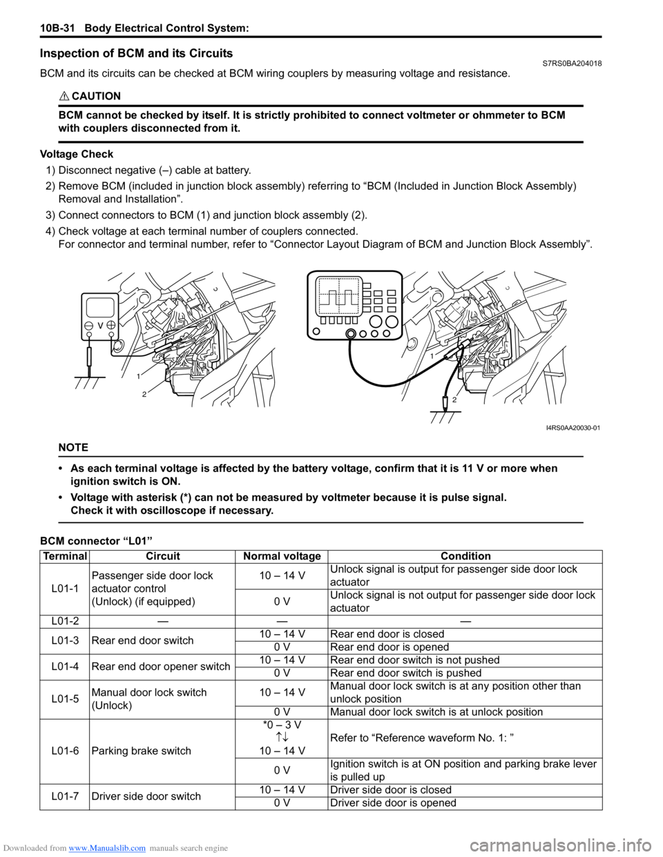
BCM and its circuits can be checked at BCM wiring couplers by measuring voltage and resistance.
CAUTION!
BCM cannot be checked by itself. It is strictly prohibited to connect voltmeter or ohmmeter to BCM
with couplers disconnected from it.
Voltage Check1) Disconnect negative (–) cable at battery.
2) Remove BCM (included in junction block assembly) refe rring to “BCM (Included in Junction Block Assembly)
Removal and Installation”.
3) Connect connectors to BCM (1) and junction block assembly (2).
4) Check voltage at each terminal number of couplers connected. For connector and terminal number, refer to “Connector Layout Diagram of BCM and Junction Block Assembly”.
NOTE
• As each terminal voltage is affected by the battery voltage, confirm that it is 11 V or more when
ignition switch is ON.
• Voltage with asterisk (*) can not be measured by voltmeter because it is pulse signal. Check it with oscilloscope if necessary.
BCM connector “L01”
1
2
1
2
I4RS0AA20030-01
Terminal CircuitNormal voltage Condition
L01-1 Passenger side door lock
actuator control
(Unlock) (if equipped) 10 – 14 V
Unlock signal is output fo
r passenger side door lock
actuator
0 V Unlock signal is not output for passenger side door lock
actuator
L01-2 — — —
L01-3 Rear end door switch 10 – 14 V Rear end door is closed
0 V Rear end door is opened
L01-4 Rear end door opener switch 10 – 14 V Rear end door switch is not pushed
0 V Rear end door switch is pushed
L01-5 Manual door lock switch
(Unlock) 10 – 14 V
Manual door lock switch is at any position other than
unlock position
0 V Manual door lock switch is at unlock position
L01-6 Parking brake switch *0 – 3 V
↑↓
10 – 14 V Refer to “Reference waveform No. 1: ”
0 V Ignition switch is at ON po
sition and parking brake lever
is pulled up
L01-7 Driver side door switch 10 – 14 V Driver side door is closed
0 V Driver side door is opened
Page 1435 of 1496
Downloaded from www.Manualslib.com manuals search engine Body Electrical Control System: 10B-32
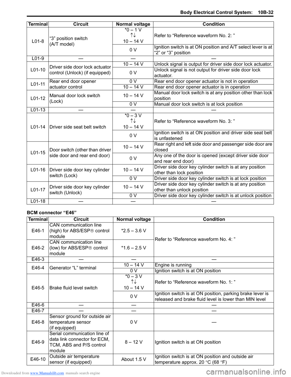
BCM connector “E46”L01-8
“3” position switch
(A/T model) *0 – 1 V
↑↓
10 – 14 V Refer to “Reference waveform No. 2: ”
0 V Ignition switch is at ON positi
on and A/T select lever is at
“2” or “3” position
L01-9 — — —
L01-10 Driver side door lock actuator
control (Unlock) (if equipped) 10 – 14 V Unlock signal is output for driver side door lock actuator.
0 V Unlock signal is not output for driver side door lock
actuator.
L01-11 Rear end door opener
actuator control 0 V Rear end door opener actuator is not in operation
10 – 14 V Rear end door opener actuator is in operation
L01-12 Manual door lock switch
(Lock) 10 – 14 V
Manual door lock switch is at any position other than lock
position
0 V Manual door lock swit ch is at lock position
L01-13 — — —
L01-14 Driver side seat belt switch *0 – 3 V
↑↓
10 – 14 V Refer to “Reference waveform No. 3: ”
0 V Ignition switch is at ON position and driver side seat belt
is unfastened
L01-15 Door switch (other than driver
side door and rear end door) 10 – 14 V
Rear right and left side door and passenger side door are
closed
0 V Any one of the door is opened (except driver side door
and rear end door)
L01-16 Driver side door key cylinder switch (Lock) 10 – 14 V
Driver side door key cylinder switch is at any position
other than lock position
0 V Driver side door key cylinder switch is at lock position
L01-17 Driver side door key cylinder
switch (Unlock) 10 – 14 V
Driver side door key cylinder switch is at any position
other than unlock position
0 V Driver side door key cylinder switch is at unlock position
L01-18 — — —
Terminal Circuit Normal voltage Condition
Terminal
CircuitNormal voltage Condition
E46-1 CAN communication line
(high) for ABS/ESP
® control
module *2.5 – 3.6 V
Refer to “Reference waveform No. 4: ”
E46-2 CAN communication line
(low) for ABS/ESP
® control
module *1.6 – 2.5 V
E46-3 — — —
E46-4 Generator “L” terminal 10 – 14 V Engine is running
0 V Ignition switch is at ON position
E46-5 Brake fluid level switch *0 – 3 V
↑↓
10 – 14 V Refer to “Reference waveform No. 1: ”
0 V Ignition switch is at ON position, parking brake lever is
released and brake fluid level is lower than MIN level
E46-6 — — —
E46-7 — — —
E46-8 Sensor ground for outside air
temperature sensor
(if equipped) 0 V
—
E46-9 Serial communication line of
data link connector for ECM,
TCM, ABS and
P/S control
module 8 – 12 V Ignition switch is at ON position
E46-10 Outside air temperature
sensor (if equipped) About 1.5 VIgnition switch is at ON position and outside air
temperature approx. 20
°C (68 °F)
Page 1439 of 1496
Downloaded from www.Manualslib.com manuals search engine Body Electrical Control System: 10B-36
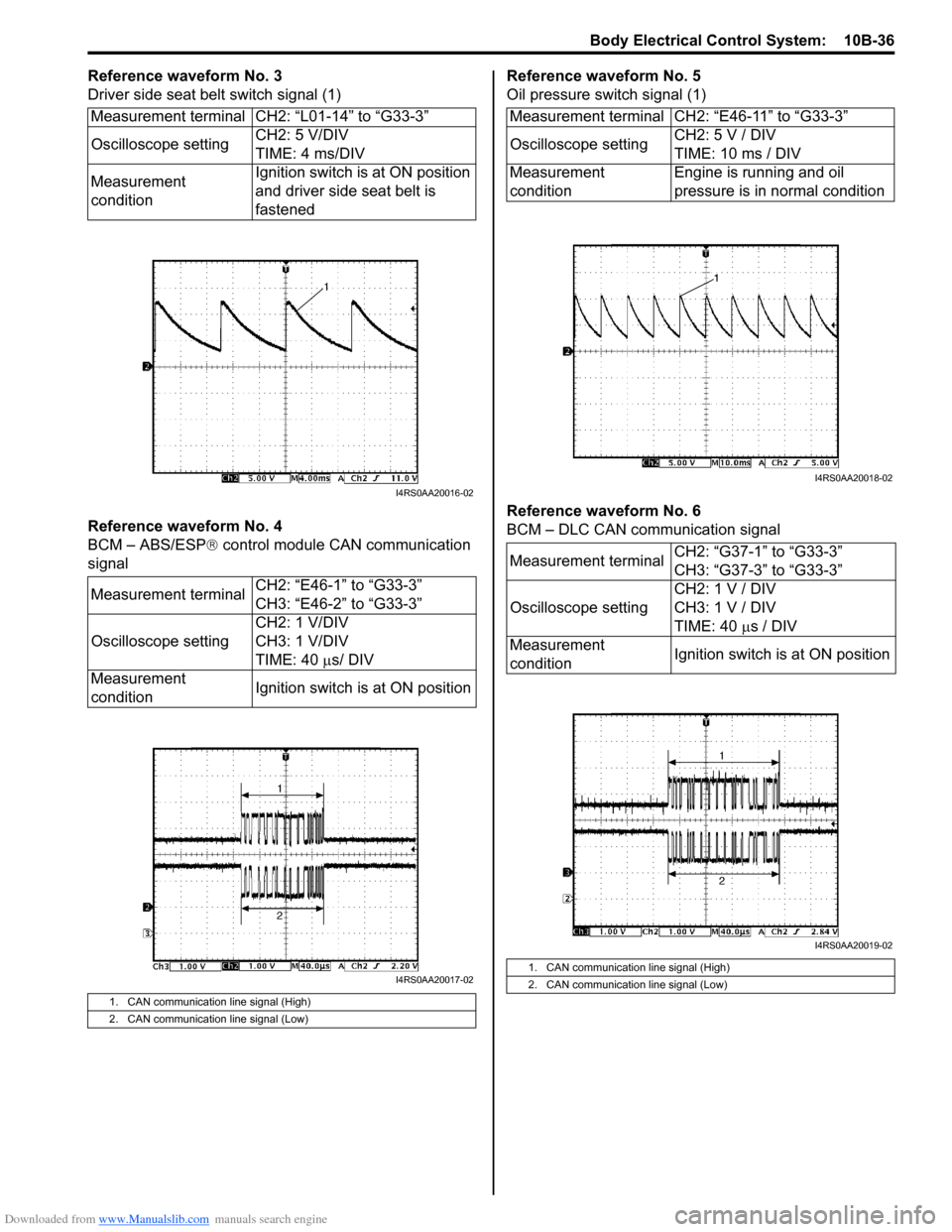
Reference waveform No. 3
Driver side seat belt switch signal (1)
Reference waveform No. 4
BCM – ABS/ESP® control module CAN communication
signal Reference waveform No. 5
Oil pressure switch signal (1)
Reference waveform No. 6
BCM – DLC CAN communication signal
Measurement terminal CH2: “L01-14” to “G33-3”
Oscilloscope setting
CH2: 5 V/DIV
TIME: 4 ms/DIV
Measurement
condition Ignition switch is at ON position
and driver side seat belt is
fastened
Measurement terminal CH2: “E46-1” to “G33-3”
CH3: “E46-2” to “G33-3”
Oscilloscope setting CH2: 1 V/DIV
CH3: 1 V/DIV
TIME: 40
µs/ DIV
Measurement
condition Ignition switch is at ON position
1. CAN communication line signal (High)
2. CAN communication line signal (Low)
I4RS0AA20016-02
I4RS0AA20017-02
Measurement terminal CH2: “E46-11” to “G33-3”
Oscilloscope settingCH2: 5 V / DIV
TIME: 10 ms / DIV
Measurement
condition Engine is running and oil
pressure is in normal condition
Measurement terminal CH2: “G37-1” to “G33-3”
CH3: “G37-3” to “G33-3”
Oscilloscope setting CH2: 1 V / DIV
CH3: 1 V / DIV
TIME: 40
µs / DIV
Measurement
condition Ignition switch is at ON position
1. CAN communication line signal (High)
2. CAN communication line signal (Low)
I4RS0AA20018-02
I4RS0AA20019-02