power SUZUKI SWIFT 2008 2.G Service Owner's Guide
[x] Cancel search | Manufacturer: SUZUKI, Model Year: 2008, Model line: SWIFT, Model: SUZUKI SWIFT 2008 2.GPages: 1496, PDF Size: 34.44 MB
Page 117 of 1496
Downloaded from www.Manualslib.com manuals search engine Engine General Information and Diagnosis: 1A-67
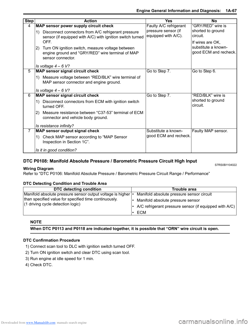
DTC P0108: Manifold Absolute Pressure / Barometric Pressure Circuit High InputS7RS0B1104022
Wiring Diagram
Refer to “DTC P0106: Manifold Absolute Pressure / Barometric Pressure Circuit Range / Performance”
DTC Detecting Condition and Trouble Area
NOTE
When DTC P0113 and P0118 are indicated together, it is possible that “ORN” wire circuit is open.
DTC Confirmation Procedure 1) Connect scan tool to DLC with ignition switch turned OFF.
2) Turn ON ignition switch and clear DTC using scan tool.
3) Run engine at idle speed for 1 min.
4) Check DTC. 4
MAP sensor power supply circuit check
1) Disconnect connectors from A/C refrigerant pressure
sensor (if equipped with A/C) with ignition switch turned
OFF.
2) Turn ON ignition switch, measure voltage between engine ground and “GRY/RED” wire terminal of MAP
sensor connector.
Is voltage 4 – 6 V? Faulty A/C refrigerant
pressure sensor (if
equipped with A/C).
“GRY/RED” wire is
shorted to ground
circuit.
If wires are OK,
substitute a known-
good ECM and recheck.
5 MAP sensor signal circuit check
1) Measure voltage between “RED/BLK” wire terminal of
MAP sensor connector and engine ground.
Is voltage 4 – 6 V? Go to Step 7. Go to Step 6.
6 MAP sensor signal circuit check
1) Disconnect connectors from ECM with ignition switch
turned OFF.
2) Measure resistance between “C37-53” terminal of ECM connector and vehicle body ground.
Is resistance infinity? Go to Step 7. “RED/BLK” wire is
shorted to ground
circuit.
7 MAP sensor output signal check
1) Check MAP sensor acco rding to “MAP Sensor
Inspection in Section 1C”.
Is it in good condition? Substitute a known-
good ECM and recheck.
Faulty MAP sensor.
Step Action Yes No
DTC detecting condition
Trouble area
Manifold absolute pressure sensor output voltage is higher
than specified value for s pecified time continuously.
(1 driving cycle detection logic) • Manifold absolute pressure sensor circuit
• Manifold absolute pressure sensor
• A/C refrigerant pressure sensor (if equipped with A/C)
•ECM
Page 118 of 1496
Downloaded from www.Manualslib.com manuals search engine 1A-68 Engine General Information and Diagnosis:
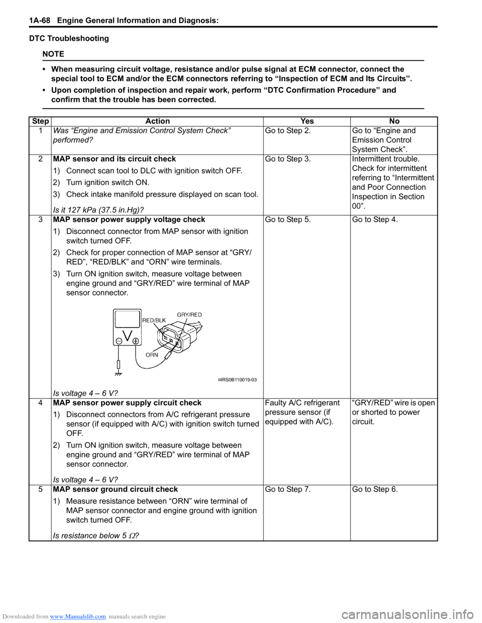
DTC Troubleshooting
NOTE
• When measuring circuit voltage, resistance and/or pulse signal at ECM connector, connect the
special tool to ECM and/or the ECM connectors re ferring to “Inspection of ECM and Its Circuits”.
• Upon completion of inspection and repair work, perform “DTC Confirmation Procedure” and confirm that the trouble has been corrected.
Step Action YesNo
1 Was “Engine and Emission Control System Check”
performed? Go to Step 2.
Go to “Engine and
Emission Control
System Check”.
2 MAP sensor and its circuit check
1) Connect scan tool to DLC with ignition switch OFF.
2) Turn ignition switch ON.
3) Check intake manifold pressure displayed on scan tool.
Is it 127 kPa (37.5 in.Hg)? Go to Step 3.
Intermittent trouble.
Check for intermittent
referring to “Intermittent
and Poor Connection
Inspection in Section
00”.
3 MAP sensor power supply voltage check
1) Disconnect connector from MAP sensor with ignition
switch turned OFF.
2) Check for proper connection of MAP sensor at “GRY/ RED”, “RED/BLK” and “ORN” wire terminals.
3) Turn ON ignition switch, measure voltage between engine ground and “GRY/RED” wire terminal of MAP
sensor connector.
Is voltage 4 – 6 V? Go to Step 5.
Go to Step 4.
4 MAP sensor power supply circuit check
1) Disconnect connectors from A/C refrigerant pressure
sensor (if equipped with A/C) with ignition switch turned
OFF.
2) Turn ON ignition switch, measure voltage between engine ground and “GRY/RED” wire terminal of MAP
sensor connector.
Is voltage 4 – 6 V? Faulty A/C refrigerant
pressure sensor (if
equipped with A/C).
“GRY/RED” wire is open
or shorted to power
circuit.
5 MAP sensor ground circuit check
1) Measure resistance between “ORN” wire terminal of
MAP sensor connector and engine ground with ignition
switch turned OFF.
Is resistance below 5
Ω? Go to Step 7.
Go to Step 6.
I4RS0B110019-03
Page 119 of 1496
Downloaded from www.Manualslib.com manuals search engine Engine General Information and Diagnosis: 1A-69
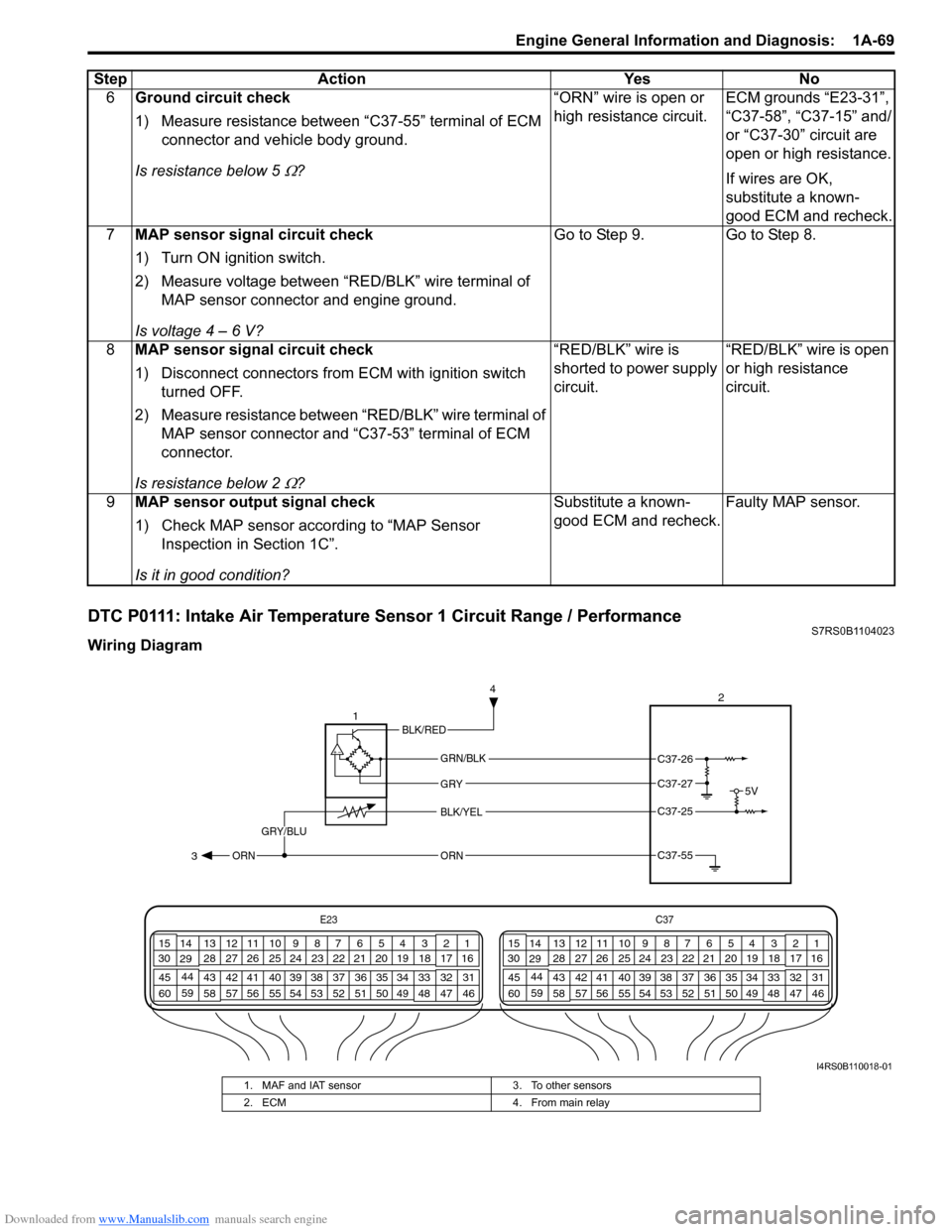
DTC P0111: Intake Air Temperature Sensor 1 Circuit Range / PerformanceS7RS0B1104023
Wiring Diagram6
Ground circuit check
1) Measure resistance between “C37-55” terminal of ECM
connector and vehicle body ground.
Is resistance below 5
Ω? “ORN” wire is open or
high resistance circuit.
ECM grounds “E23-31”,
“C37-58”, “C37-15” and/
or “C37-30” circuit are
open or high resistance.
If wires are OK,
substitute a known-
good ECM and recheck.
7 MAP sensor signal circuit check
1) Turn ON ignition switch.
2) Measure voltage between “RED/BLK” wire terminal of
MAP sensor connector and engine ground.
Is voltage 4 – 6 V? Go to Step 9. Go to Step 8.
8 MAP sensor signal circuit check
1) Disconnect connectors from ECM with ignition switch
turned OFF.
2) Measure resistance between “RED/BLK” wire terminal of MAP sensor connector and “C37-53” terminal of ECM
connector.
Is resistance below 2
Ω? “RED/BLK” wire is
shorted to power supply
circuit.
“RED/BLK” wire is open
or high resistance
circuit.
9 MAP sensor output signal check
1) Check MAP sensor acco rding to “MAP Sensor
Inspection in Section 1C”.
Is it in good condition? Substitute a known-
good ECM and recheck.
Faulty MAP sensor.
Step Action Yes No
E23
C37
34
1819
567
1011
17
20
47 46
495051
2122
52 16
25 9
24
14
29
55
57 54 53
59
60 58 2
262728
15
30
56 4832 31
34353637
40
42 39 38
44
45 43 41 331
1213
238
34
1819
567
1011
17
20
47 46
495051
2122
52 16
25 9
24
14
29
55
57 54 53
59
60 58 2
262728
15
30
56 4832 31
34353637
40
42 39 38
44
45 43 41 331
1213
238
5V
2
BLK/YEL
GRY/BLU
GRY
ORN
1
GRN/BLK
C37-25
C37-55 3 4ORN
C37-26
C37-27
BLK/RED
I4RS0B110018-01
1. MAF and IAT sensor
3. To other sensors
2. ECM 4. From main relay
Page 135 of 1496
Downloaded from www.Manualslib.com manuals search engine Engine General Information and Diagnosis: 1A-85
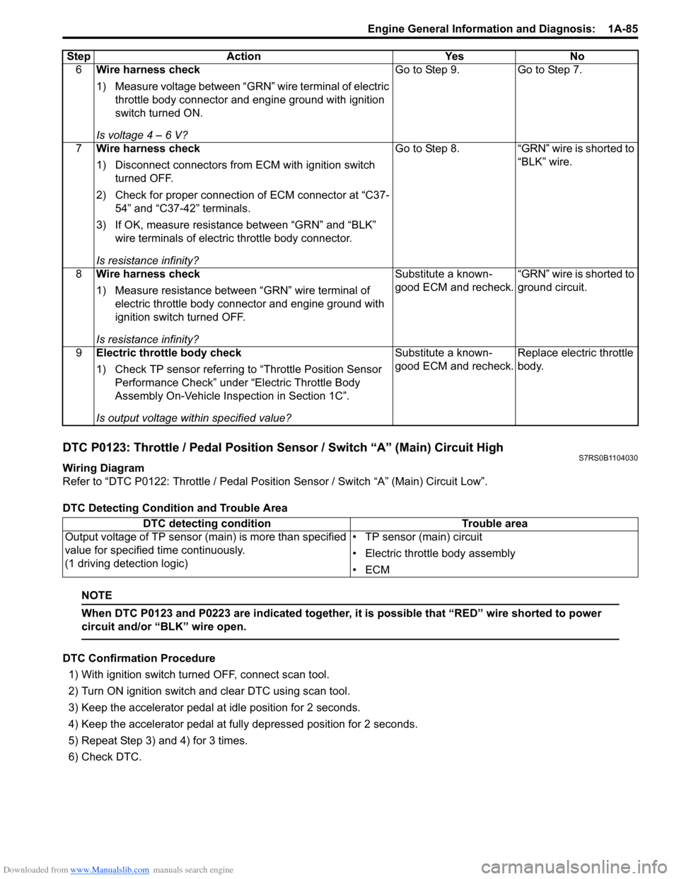
DTC P0123: Throttle / Pedal Position Sensor / Switch “A” (Main) Circuit HighS7RS0B1104030
Wiring Diagram
Refer to “DTC P0122: Throttle / Pedal Position Sensor / Switch “A” (Main) Circuit Low”.
DTC Detecting Condition and Trouble Area
NOTE
When DTC P0123 and P0223 are indicated together, it is possible that “RED” wire shorted to power
circuit and/or “BLK” wire open.
DTC Confirmation Procedure
1) With ignition switch turned OFF, connect scan tool.
2) Turn ON ignition switch and clear DTC using scan tool.
3) Keep the accelerator pedal at idle position for 2 seconds.
4) Keep the accelerator pedal at fully depressed position for 2 seconds.
5) Repeat Step 3) and 4) for 3 times.
6) Check DTC. 6
Wire harness check
1) Measure voltage between “GRN” wire terminal of electric
throttle body connector and engine ground with ignition
switch turned ON.
Is voltage 4 – 6 V? Go to Step 9. Go to Step 7.
7 Wire harness check
1) Disconnect connectors from ECM with ignition switch
turned OFF.
2) Check for proper connection of ECM connector at “C37- 54” and “C37-42” terminals.
3) If OK, measure resistance between “GRN” and “BLK” wire terminals of electric throttle body connector.
Is resistance infinity? Go to Step 8. “GRN” wire is shorted to
“BLK” wire.
8 Wire harness check
1) Measure resistance between “GRN” wire terminal of
electric throttle body connector and engine ground with
ignition switch turned OFF.
Is resistance infinity? Substitute a known-
good ECM and recheck.
“GRN” wire is shorted to
ground circuit.
9 Electric throttle body check
1) Check TP sensor referring to “Throttle Position Sensor
Performance Check” under “Electric Throttle Body
Assembly On-Vehicle Inspection in Section 1C”.
Is output voltage within specified value? Substitute a known-
good ECM and recheck.
Replace electric throttle
body.
Step Action Yes No
DTC detecting condition
Trouble area
Output voltage of TP sensor (main) is more than specified
value for specified time continuously.
(1 driving detection logic) • TP sensor (main) circuit
• Electric throttle body assembly
•ECM
Page 136 of 1496
Downloaded from www.Manualslib.com manuals search engine 1A-86 Engine General Information and Diagnosis:
DTC Troubleshooting
NOTE
• When measuring circuit voltage, resistance and/or pulse signal at ECM connector, connect the
special tool to ECM and/or the ECM connectors re ferring to “Inspection of ECM and Its Circuits”.
• Upon completion of inspection and repair work, perform “DTC Confirmation Procedure” and confirm that the trouble has been corrected.
Step Action YesNo
1 Was “Engine and Emission Control System Check”
performed? Go to Step 2.
Go to “Engine and
Emission Control
System Check”.
2 TP sensor and its circuit check
1) Connect scan tool to DLC with ignition switch turned
OFF.
2) Turn ON ignition switch, check “TP Sensor 1 Volt” displayed on scan tool when accelerator pedal is idle
position and fully depressed.
Is displayed TP sensor value as described voltage in “Scan
To o l D a t a ” ? Intermittent trouble.
Check for intermittent
referring to “Intermittent
and Poor Connection
Inspection in Section
00”.
Go to Step 3.
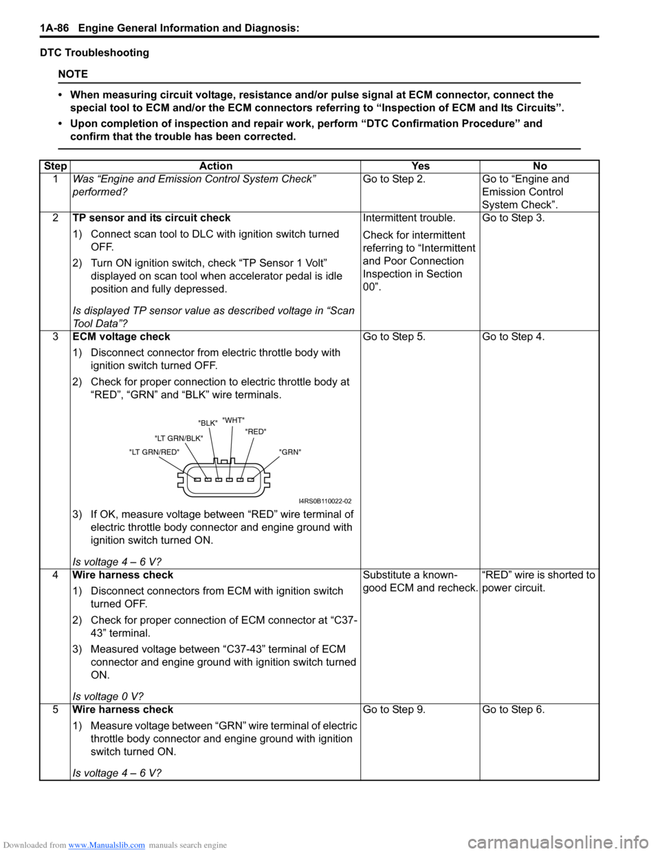
3 ECM voltage check
1) Disconnect connector from electric throttle body with
ignition switch turned OFF.
2) Check for proper connection to electric throttle body at “RED”, “GRN” and “BLK” wire terminals.
3) If OK, measure voltage between “RED” wire terminal of electric throttle body connector and engine ground with
ignition switch turned ON.
Is voltage 4 – 6 V? Go to Step 5.
Go to Step 4.
4 Wire harness check
1) Disconnect connectors from ECM with ignition switch
turned OFF.
2) Check for proper connection of ECM connector at “C37- 43” terminal.
3) Measured voltage between “C37-43” terminal of ECM connector and engine ground with ignition switch turned
ON.
Is voltage 0 V? Substitute a known-
good ECM and recheck.
“RED” wire is shorted to
power circuit.
5 Wire harness check
1) Measure voltage between “GRN” wire terminal of electric
throttle body connector and engine ground with ignition
switch turned ON.
Is voltage 4 – 6 V? Go to Step 9.
Go to Step 6.
"GRN"
"RED"
"WHT"
"BLK"
"LT GRN/BLK"
"LT GRN/RED"
I4RS0B110022-02
Page 137 of 1496
Downloaded from www.Manualslib.com manuals search engine Engine General Information and Diagnosis: 1A-87
6Wire harness check
1) Turn OFF ignition switch.
2) Remove ECM from its br acket with ECM connectors
connected.
3) Check for proper connection of ECM connector at “C37- 43” and “C37-54” terminals.
4) If OK, measure voltage between “C37-54” terminal of ECM connector and engine ground with ignition switch
turned ON.
Is voltage 4 -6 V? “GRN” wire is open or
high resistance circuit.
Go to Step 7.
7 Wire harness check
1) Disconnect connectors from ECM with ignition switch
turned OFF.
2) Measure resistance between “GRN” and “RED” wire terminals of electric th rottle body connector.
Is resistance infinity? Go to Step 8. “GRN” wire is shorted to
“RED” wire.
8 Wire harness check
1) Turn ON ignition switch.
2) Measure voltage between “C37-54” terminal of ECM
connector and engine ground.
Is voltage 0 V? Substitute a known-
good ECM and recheck.
“GRN” wire is shorted to
power circuit.
9 Ground circuit check
1) Turn OFF ignition switch.
2) Measure resistance between “BLK” wire terminal of
electric throttle body connector and engine ground.
Is resistance below 5
Ω? Go to Step 11. Go to Step 10.
10 Ground circuit check
1) Remove ECM from its br acket with ECM connectors
connected.
2) Check for proper connection of ECM connector at “C37- 42” terminal.
3) Measure resistance between “C37-42” terminal of ECM connector and engine ground with ignition switch turned
OFF.
Is resistance below 5
Ω? “BLK” wire is open or
high resistance circuit.
Faulty ECM ground
circuit. If circuit is OK,
substitute a known-
good ECM and recheck.
11 Electric throttle body check
1) Check TP sensor referring to “Throttle Position Sensor
Performance Check” under “Electric Throttle Body
Assembly On-Vehicle Inspection in Section 1C”.
Is output voltage within specified value? Substitute a known-
good ECM and recheck.
Replace electric throttle
body.
Step Action Yes No
Page 153 of 1496
Downloaded from www.Manualslib.com manuals search engine Engine General Information and Diagnosis: 1A-103
NOTE
When DTC P0123 and P0223 are indicated together, it is possible that “RED” wire shorted to power
circuit and/or “BLK” wire open.
DTC Confirmation Procedure
1) With ignition switch turned OFF, connect scan tool.
2) Turn ON ignition switch and clear DTC using scan tool.
3) Keep the accelerator pedal at idle position for 2 seconds.
4) Keep the accelerator pedal at fully depressed position for 2 seconds.
5) Repeat Step 3) and 4) for 3 times.
6) Check DTC.
DTC Troubleshooting
NOTE
• When measuring circuit voltage, resistance and/ or pulse signal at ECM connector, connect the
special tool to ECM and/or the ECM connectors re ferring to “Inspection of ECM and Its Circuits”.
• Upon completion of inspection and repair work, perform “DTC Confirmation Procedure” and confirm that the trouble has been corrected.
Step Action YesNo
1 Was “Engine and Emission Control System Check”
performed? Go to Step 2.
Go to “Engine and
Emission Control
System Check”.
2 TP sensor and its circuit check
1) Connect scan tool to DLC with ignition switch turned
OFF.
2) Turn ON ignition switch, check “TP Sensor 2 Volt” displayed on scan tool when accelerator pedal is idle
position and fully depressed.
Is displayed TP sensor value as described voltage in “Scan
To o l D a t a ” ? Intermittent trouble.
Check for intermittent
referring to “Intermittent
and Poor Connection
Inspection in Section
00”.
Go to Step 3.
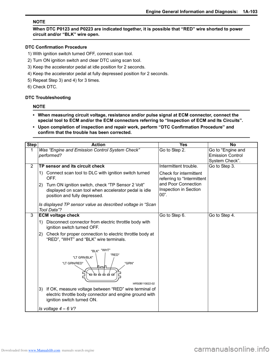
3 ECM voltage check
1) Disconnect connector from electric throttle body with
ignition switch turned OFF.
2) Check for proper connection to electric throttle body at “RED”, “WHT” and “BLK” wire terminals.
3) If OK, measure voltage between “RED” wire terminal of electric throttle body connector and engine ground with
ignition switch turned ON.
Is voltage 4 – 6 V? Go to Step 6.
Go to Step 4.
"GRN"
"RED"
"WHT"
"BLK"
"LT GRN/BLK"
"LT GRN/RED"
I4RS0B110022-02
Page 154 of 1496
Downloaded from www.Manualslib.com manuals search engine 1A-104 Engine General Information and Diagnosis:
4Wire harness check
1) Disconnect connectors from ECM with ignition switch
turned OFF.
2) Check for proper connection of ECM connector at “C37- 43” terminal.
3) Measure voltage between “C37-43” terminal of ECM connector and engine ground with ignition switch turned
ON.
Is voltage 0 V? Substitute a known-
good ECM and recheck.
“RED” wire is shorted to
power circuit.
5 Wire harness check
1) Measure voltage between “WHT” wire terminal of
electric throttle body connector and engine ground with
ignition switch turned ON.
Is voltage 4 – 6 V? Go to Step 9.
Go to Step 6.
6 Wire harness check
1) Turn OFF ignition switch.
2) Remove ECM from its br acket with ECM connectors
connected.
3) Check for proper connection of ECM connector at “C37- 43” and “C37-40” terminals.
4) If OK, measure voltage between “C37-40” terminal of ECM connector and engine ground with ignition switch
turned ON.
Is voltage 4 – 6 V? “WHT” wire is open or
high resistance circuit.
Go to Step 7.
7 Wire harness check
1) Disconnect connectors from ECM with ignition switch
turned OFF.
2) Measure resistance between “WHT” and “RED” wire terminals of electric thrott le body assembly connector.
Is resistance infinity? Go to Step 8.
“WHT” wire is shorted to
“RED” wire.
8 Wire harness check
1) Turn ON ignition switch.
2) Measure voltage between “C37-40” terminal of ECM
connector and engine ground.
Is voltage 0 V? Substitute a known-
good ECM and recheck.
“WHT” wire is shorted to
power circuit.
9 Ground circuit check
1) Turn OFF ignition switch.
2) Measure resistance between “BLK” wire terminal of
electric throttle body connector and engine ground.
Is resistance below 5
Ω? Go to Step 11. Go to Step 10.
10 Ground circuit check
1) Remove ECM from its br acket with ECM connectors
connected.
2) Check for proper connection of ECM connector at “C37- 42” terminal.
3) Measure resistance between “C37-42” terminal of ECM connector and engine ground with ignition switch turned
OFF.
Is resistance below 5
Ω? “BLK” wire is open or
high resistance circuit.
Faulty ECM ground
circuit. If circuit is OK,
substitute a known-
good ECM and recheck.
Step Action Yes No
Page 160 of 1496
Downloaded from www.Manualslib.com manuals search engine 1A-110 Engine General Information and Diagnosis:
DTC Troubleshooting
NOTE
• When measuring circuit voltage, resistance and/or pulse signal at ECM connector, connect the
special tool to ECM and/or the ECM connectors re ferring to “Inspection of ECM and Its Circuits”.
• Upon completion of inspection and repair work, perform “DTC Confirmation Procedure” and confirm that the trouble has been corrected.
Step Action YesNo
1 Was “Engine and Emission Control System Check”
performed? Go to Step 2.
Go to “Engine and
Emission Control
System Check”.
2 CKP sensor and connector for proper installation check
Is CKP sensor installed properly and connector connected
securely? Go to Step 3.
Correct.
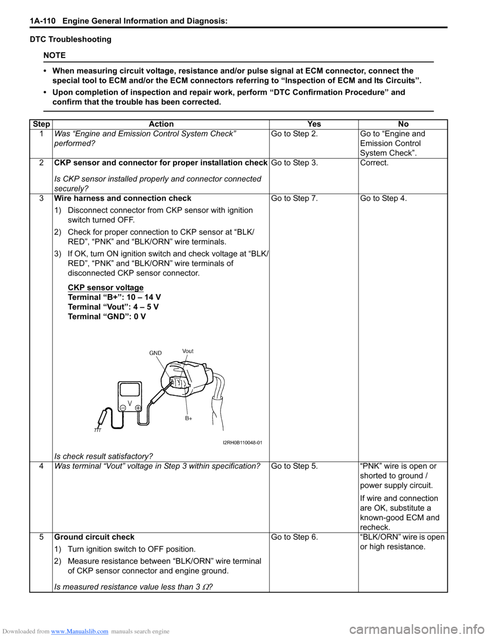
3 Wire harness and connection check
1) Disconnect connector from CKP sensor with ignition
switch turned OFF.
2) Check for proper connection to CKP sensor at “BLK/ RED”, “PNK” and “BLK/ORN” wire terminals.
3) If OK, turn ON ignition switch and check voltage at “BLK/ RED”, “PNK” and “BLK/ORN” wire terminals of
disconnected CKP sensor connector.
CKP sensor voltage
Terminal “B+”: 10 – 14 V
Terminal “Vout”: 4 – 5 V
Terminal “GND”: 0 V
Is check result satisfactory? Go to Step 7. Go to Step 4.
4 Was terminal “Vout” voltage in Step 3 within specification? Go to Step 5. “PNK” wire is open or
shorted to ground /
power supply circuit.
If wire and connection
are OK, substitute a
known-good ECM and
recheck.
5 Ground circuit check
1) Turn ignition switch to OFF position.
2) Measure resistance between “BLK/ORN” wire terminal
of CKP sensor connector and engine ground.
Is measured resistance value less than 3
Ω? Go to Step 6. “BLK/ORN” wire is open
or high resistance.
I2RH0B110048-01
Page 163 of 1496
Downloaded from www.Manualslib.com manuals search engine Engine General Information and Diagnosis: 1A-113
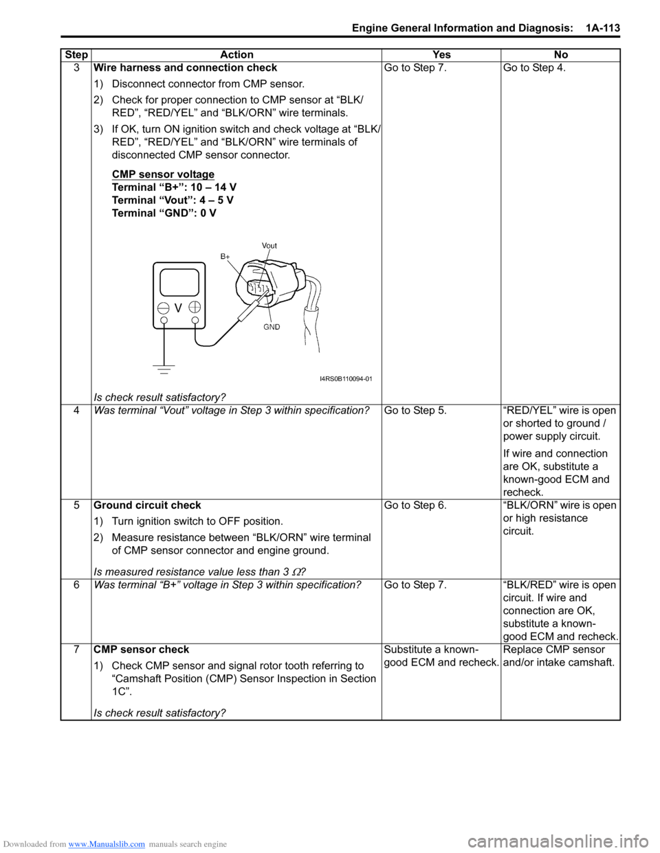
3Wire harness and connection check
1) Disconnect connector from CMP sensor.
2) Check for proper connection to CMP sensor at “BLK/
RED”, “RED/YEL” and “B LK/ORN” wire terminals.
3) If OK, turn ON ignition switch and check voltage at “BLK/ RED”, “RED/YEL” and “BLK/ORN” wire terminals of
disconnected CMP sensor connector.
CMP sensor voltage
Terminal “B+”: 10 – 14 V
Terminal “Vout”: 4 – 5 V
Terminal “GND”: 0 V
Is check result satisfactory? Go to Step 7. Go to Step 4.
4 Was terminal “Vout” voltage in Step 3 within specification? Go to Step 5. “RED/YEL” wire is open
or shorted to ground /
power supply circuit.
If wire and connection
are OK, substitute a
known-good ECM and
recheck.
5 Ground circuit check
1) Turn ignition switch to OFF position.
2) Measure resistance between “BLK/ORN” wire terminal
of CMP sensor connector and engine ground.
Is measured resistance value less than 3
Ω? Go to Step 6. “BLK/ORN” wire is open
or high resistance
circuit.
6 Was terminal “B+” voltage in Step 3 within specification? Go to Step 7. “BLK/RED” wire is open
circuit. If wire and
connection are OK,
substitute a known-
good ECM and recheck.
7 CMP sensor check
1) Check CMP sensor and signal rotor tooth referring to
“Camshaft Position (CMP) Sensor Inspection in Section
1C”.
Is check result satisfactory? Substitute a known-
good ECM and recheck.
Replace CMP sensor
and/or intake camshaft.
Step Action Yes No
I4RS0B110094-01