steering parts SUZUKI SWIFT 2008 2.G Service Owner's Guide
[x] Cancel search | Manufacturer: SUZUKI, Model Year: 2008, Model line: SWIFT, Model: SUZUKI SWIFT 2008 2.GPages: 1496, PDF Size: 34.44 MB
Page 1402 of 1496

Downloaded from www.Manualslib.com manuals search engine 10-ii Table of Contents
DTC P1615: ID Code Does Not Registered (Vehicle equipped with keyless start system
only) ................................................................10C-9
DTC P1616: Different Registration ID Codes (Vehicle equipped with keyless start system
only) ..............................................................10C-10
DTC P1618: CAN Communication Error (Reception Error for Keyless Start Control
Module) (Vehicle equipped with keyless
start system only) ..........................................10C-11
DTC P1621: Immobilizer Communication Line Error ......................................................10C-12
DTC P1622: EEPROM Reading / Writing Error ..............................................................10C-13
DTC P1623: Unregistered Transponder .........10C-13
DTC P1625: Immobilizer An tenna Error..........10C-14
DTC P1636: Immobilizer Information Registration Failure .......................................10C-14
DTC P1638: Immobilizer Information Mismatched ...................................................10C-15
Inspection of Immobilizer Control Module (ICM) and Its Circuit ....... ...............................10C-16
Repair Instructions ........... ...............................10C-18
Immobilizer Control Mo dule (ICM) Removal
and Installation ..............................................10C-18
Registration of the Ignition Key .......................10C-18
Procedure after ECM Replacement ................10C-18
Special Tools and Equipmen t .........................10C-19
Special Tool ....................................................10C-19
Keyless Start System ....... ......................10E-1
General Description ........................................... 10E-1
Keyless Start System Description ..................... 10E-1
Parts and Functions .......................................... 10E-2
Keyless Engine Start Function .......................... 10E-3
Door Lock Function of Keyless Start System .... 10E-4
Operation Area of Remote Controller................ 10E-5
Alarm Function .................................................. 10E-6
CAN Communication System Description......... 10E-6
Schematic and Routing Diagram ...................... 10E-7 Keyless Start System El ectric Wiring Circuit
Diagram .......................................................... 10E-7
Diagnostic Information and Procedures .......... 10E-8 Precautions in Diagnosing Troubles ................. 10E-8
Self-Diagnosis Function .................................... 10E-8
Keyless Start System Diagn osis Introduction ... 10E-8 Keyless Start System Chec
k ............................. 10E-8
Customer Questionnaire (E xample) .................. 10E-9
Key Indicator Lamp Check .............................. 10E-10
DTC Check...................................................... 10E-10
DTC Table ....................................................... 10E-11
DTC Clearance ............................................... 10E-12
Keyless Start System Symp tom Diagnosis ..... 10E-12
Keyless Start System Operation Inspection .... 10E-13
Door Lock Operation (Keyless Start System) . 10E-14
Inspection of Keyless Start Control Module and Its Circuits .............................................. 10E-14
No DTC Detection After Performing DTC Check ............................................................ 10E-18
Key Indicator Lamp Circuit Check (Key indicator lamp doesn’t light when ignition
knob switch is pushed.) ................................. 10E-20
Keyless Start Control Module Power and Ground Circuit Check .................................... 10E-22
DTC No. 11: Communi cation Error with
Steering Lock Unit ......................................... 10E-23
DTC No. 13 / No. 14: Release Signal Error from Steering Lock Unit / Steering Lock Unit
Malfunction .................................................... 10E-24
DTC No. 21 / No. 22: Internal Error of Keyless Start Control Module (EEPROM reading
error) / (EEPROM writing error) ............ ........ 10E-24
DTC No. 31: Lost Commun ication with BCM .. 10E-25
DTC No. 33: Control Module Communication
Bus Off .......................................................... 10E-27
DTC No. 51 / No. 52 / No. 53: Driver Side / Passenger Side / Rear End Door Request
Switch Failure................................................ 10E-28
Repair Instructions ............ .............................. 10E-30
Antennas and Request Switches Removal and Installation .............................................. 10E-30
Front Door (Driver and Passenger Side), Rear End Door Request Switch Inspection............ 10E-31
Steering Lock Unit Removal and Installation .. 10E-31
Steering Lock Unit Inspection ......................... 10E-31
Front Door Lock Switch In spection ................. 10E-31
Keyless Start Control Module Removal and Installation ..................................................... 10E-32
Remote Controller Inspection.......................... 10E-32
Replacement of Remote Controller Battery .... 10E-32
Registration Procedure for Remote Controller
ID Code ......................................................... 10E-33
Page 1463 of 1496

Downloaded from www.Manualslib.com manuals search engine Keyless Start System: 10E-1
Control Systems
Keyless Start System
General Description
Keyless Start System DescriptionS7RS0BA501001
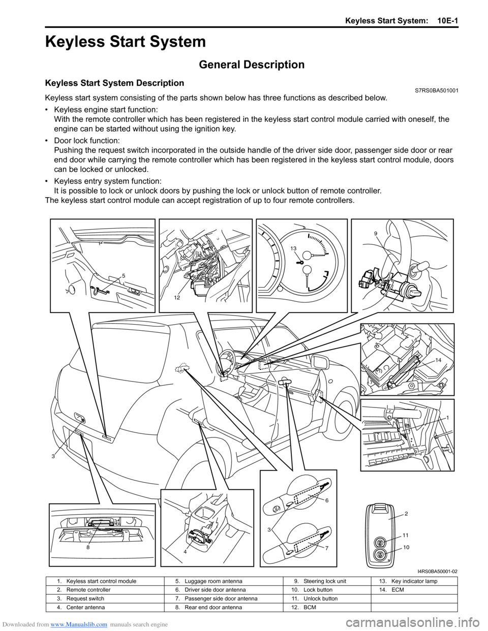
Keyless start system consisting of the parts shown below has three functions as described below.
• Keyless engine start function:With the remote controller which has been registered in the keyless start control module carried with oneself, the
engine can be started without using the ignition key.
• Door lock function: Pushing the request switch incorporated in the outside handl e of the driver side door, passenger side door or rear
end door while carrying the remote controller which has been registered in the keyless start control module, doors
can be locked or unlocked.
• Keyless entry system function: It is possible to lock or unlock doors by push ing the lock or unlock button of remote controller.
The keyless start control module can accept regi stration of up to four remote controllers.
5
12
13
9
14
1
2
6
3
748
3
11
10
I4RS0BA50001-02
1. Keyless start control module 5. Luggage room antenna 9. Steering lock unit13. Key indicator lamp
2. Remote controller 6. Driver side door antenna10. Lock button14. ECM
3. Request switch 7. Passenger side door antenna11. Unlock button
4. Center antenna 8. Rear end door antenna12. BCM
Page 1464 of 1496

Downloaded from www.Manualslib.com manuals search engine 10E-2 Keyless Start System:
Parts and FunctionsS7RS0BA501002
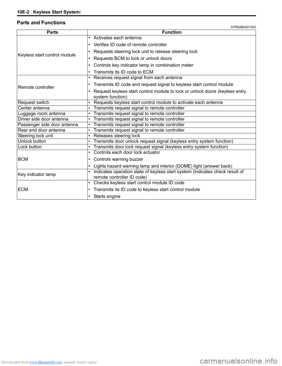
PartsFunction
Keyless start control module • Activates each antenna
• Verifies ID code of remote controller
• Requests steering lock unit to release steering lock
• Requests BCM to lock or unlock doors
• Controls key indicator la
mp in combination meter
• Transmits its ID code to ECM
Remote controller • Receives request signal from each antenna
• Transmits ID code and request signal to keyless start control module
• Request keyless start control module to lock or unlock doors (keyless entry
system function)
Request switch • Requests keyless start control module to activate each antenna
Center antenna • Transmits request signal to remote controller
Luggage room antenna • Transmits request signal to remote controller
Driver side door antenna • Transmits request signal to remote controller
Passenger side door antenna • Transmits request signal to remote controller
Rear end door antenna • Transmits request signal to remote controller
Steering lock unit • Releases steering lock
Unlock button • Transmits door unlock request signal (keyless entry system function)
Lock button • Transmits door lock request signal (keyless entry system function)
BCM • Controls each door lock actuator
• Controls warning buzzer
• Lights hazard warning lamp and interior (DOME) light (answer back)
Key indicator lamp • Indicates operation state of keyless start system (indicates check result of
remote controller ID code)
ECM • Checks keyless start control module ID code
• Transmits its ID code to keyless start control module
• Starts engine
Page 1473 of 1496

Downloaded from www.Manualslib.com manuals search engine Keyless Start System: 10E-11
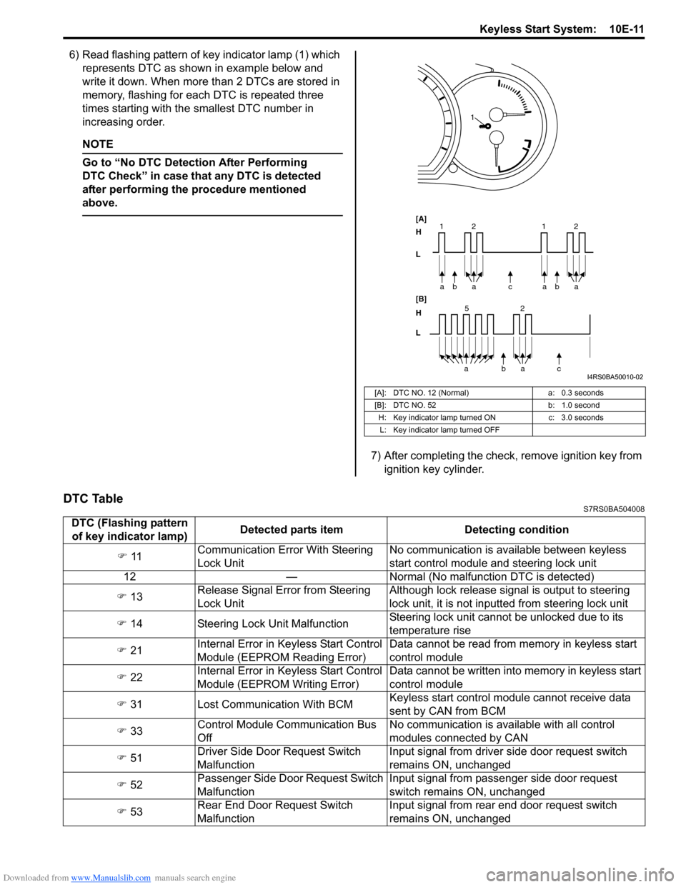
6) Read flashing pattern of key indicator lamp (1) which represents DTC as shown in example below and
write it down. When more than 2 DTCs are stored in
memory, flashing for each DTC is repeated three
times starting with the smallest DTC number in
increasing order.
NOTE
Go to “No DTC Detect ion After Performing
DTC Check” in case that any DTC is detected
after performing the procedure mentioned
above.
7) After completing the check, remove ignition key from ignition key cylinder.
DTC TableS7RS0BA504008
[A]: DTC NO. 12 (Normal)
a: 0.3 seconds
[B]: DTC NO. 52 b: 1.0 second
H: Key indicator lamp tu rned ONc: 3.0 seconds
L: Key indicator lamp turned OFF
bc
a
a
[A]
H
L
H
L [B]
52
bac
a
2
11baa 2
1
I4RS0BA50010-02
DTC (Flashing pattern
of key indicator lamp) Detected parts item Detecting condition
�) 11 Communication Error With Steering
Lock Unit No communication is available between keyless
start control module and steering lock unit
12 — Normal (No malfunct ion DTC is detected)
�) 13 Release Signal Error from Steering
Lock Unit Although lock release signal is output to steering
lock unit, it is not inputt
ed from steering lock unit
�) 14 Steering Lock Unit Malfunction Steering lock unit cannot be unlocked due to its
temperature rise
�) 21 Internal Error in Ke
yless Start Control
Module (EEPROM Reading Error) Data cannot be read from memory in keyless start
control module
�) 22 Internal Error in Ke
yless Start Control
Module (EEPROM Writing Error) Data cannot be written into memory in keyless start
control module
�) 31 Lost Communication With BCM Keyless start control module cannot receive data
sent by CAN from BCM
�) 33 Control Module Communication Bus
Off No communication is available with all control
modules connected by CAN
�) 51 Driver Side Door Request Switch
Malfunction Input signal from driver side door request switch
remains ON, unchanged
�) 52 Passenger Side Door Request Switch
Malfunction Input signal from passenger side door request
switch remains ON, unchanged
�) 53 Rear End Door Request Switch
Malfunction Input signal from rear end door request switch
remains ON, unchanged