replace brake fluid SUZUKI SWIFT 2008 2.G Service Service Manual
[x] Cancel search | Manufacturer: SUZUKI, Model Year: 2008, Model line: SWIFT, Model: SUZUKI SWIFT 2008 2.GPages: 1496, PDF Size: 34.44 MB
Page 1168 of 1496

Downloaded from www.Manualslib.com manuals search engine 9-ii Table of Contents
List of Connectors ........................................... 9A-103
C Connector .................................................... 9A-103
D Connector (M16A engine) ........................... 9A-104
E Connector .................................................... 9A-104
G Connector .................................................... 9A-106
J Connector ..................................................... 9A-108
K Connector .................................................... 9A-109
L Connector..................................................... 9A-109
M Connector (SPORT model) ......................... 9A-111
O Connector .................................................... 9A-111
R Connector .................................................... 9A-111
Lighting Systems .................................... 9B-1
Component Location ........... ................................9B-1
Lighting System Component s Location............... 9B-1
Interior Light System Location............................. 9B-2
Diagnostic Information and Procedures ............ 9B-2 Headlight Symptom Diagnosis ............................ 9B-2
Headlight Leveling System Symptom Diagnosis (If Equipped) ..................................... 9B-2
Turn Signal and Hazard Warning Light Symptom Diagnosis .......................................... 9B-3
Clearance, Tail and License Plate Light Symptom Diagnosis .......................................... 9B-3
Back-Up Light Symptom Diagnosis..................... 9B-4
Brake Light Symptom Diagnosis ......................... 9B-4
Front Fog Light Symptom Diagnosis (If Equipped) .......................................................... 9B-4
Interior Light Symptom Diagnosis ....................... 9B-5
Repair Instructions ..............................................9B-5 Headlight Housing Removal and Installation ...... 9B-5
Headlight Bulb Replacemen t............................... 9B-6
Headlight Aiming Adjustment with Screen .......... 9B-6
Headlight Switch (in Lighting Switch) Removal and Installation ................................... 9B-8
Headlight Switch (in Lighting Switch) Inspection .......................................................... 9B-8
Hazard Warning Switch Removal and Installation ......................................................... 9B-8
Hazard Warning Switch Inspection ..................... 9B-9
Brake Light Switch Inspection ............................. 9B-9
Turn Signal Light Switch (in Lighting Switch) Removal and Installation ................................... 9B-9
Turn Signal Light Switch (in Lighting Switch) Inspection .......................................................... 9B-9
Turn Signal and Hazard Warning Relay Removal and Installation ................................... 9B-9
Turn Signal and Hazard Warning Relay Inspection ........................................................ 9B-10
License Light Removal and Installation............. 9B-10
Front Fog Light Removal and Installation (If Equipped) ........................................................ 9B-11
Front Fog Light Bulb Replacement (If Equipped) ........................................................ 9B-11
Front Fog Light Switch Inspection (If Equipped) ........................................................ 9B-11
Front Fog Light Relay Inspection (If Equipped) ........................................................ 9B-11
Front Fog Light Aiming Adjustment with Screen (If Equipped) ....................................... 9B-12 Headlight Leveling Switch Inspection (If
Equipped) ........................................................ 9B-13
Headlight Leveling Actuator Inspection (If Equipped) ........................................................ 9B-13
Instrumentation / Driver Info. / Horn ...... 9C-1
Precautions ...........................................................9C-1 Precautions in Diagnosing Troubles for Combination Meter ............................................9C-1
General Description .............................................9C-1 CAN Communication System Description...........9C-1
Auto Volume Co ntrol System Description (If
Equipped) ..........................................................9C-3
Schematic and Routing Diagram ........................9C-4 Combination Meter Circuit Diagram ....................9C-4
Component Location ............ ...............................9C-6
Audio System Component Location ....................9C-6
Diagnostic Information and Procedures ............9C-6 Speedometer and VSS Symp tom Diagnosis ......9C-6
Tachometer Symptom Diagnosis ........................9C-6
Engine Coolant Temperature (ECT) Meter Symptom Diagnosis ..........................................9C-7
Fuel Meter Symptom Diagnosis ..........................9C-7
Low Fuel Warning Light Symptom Diagnosis .....9C-7
Oil Pressure Warning Light Symptom Diagnosis ..........................................................9C-8
Brake and Parking Brake Warning Light Symptom Diagnosis ..........................................9C-8
Seat Belt Reminder Light Symptom Diagnosis (If Equipped)......................................................9C-8
A/T Shift Position Indicator Symptom Diagnosis (A/T Model).......................................9C-9
Charge Warning Light Sy mptom Diagnosis ........9C-9
Main Beam (High Beam) Indicator Symptom Diagnosis ..........................................................9C-9
Warning Buzzer Circuit Sy mptom Diagnosis ....9C-10
Cigarette Lighter Symptom Diagnosis (If Equipped) ........................................................9C-10
Horn Symptom Diagnosis .................................9C-10
Information Display Symptom Diagnosis (If Equipped) ........................................................9C-11
Clock Symptom Diagnosis (If Equipped)...........9C-12
Audio System Symptom Diagnosis (If Equipped) ........................................................9C-12
Remote Audio Control Switch Symptom Diagnosis (If Equipped) ...................................9C-13
Navigation Symptom Diagnosis (If Equipped)...9C-14
Repair Instructions ............ ................................9C-14
Ignition Switch Removal and Installation...........9C-14
Ignition Switch Inspection..................................9C-14
Combination Meter Removal and Installation ...9C-15
Fuel Level Sensor Removal and Installation .....9C-15
Fuel Level Sensor Inspection ............................9C-15
Oil Pressure Switch Remova l and Installation ..9C-15
Oil Pressure Switch Inspec tion .........................9C-16
Engine Coolant Temperature (ECT) Sensor Inspection ........................................................9C-16
Brake Fluid Level Switch Inspection .................9C-16
Parking Brake Switch Inspec tion.......................9C-16
Page 1303 of 1496

Downloaded from www.Manualslib.com manuals search engine Instrumentation / Driver Info. / Horn: 9C-8
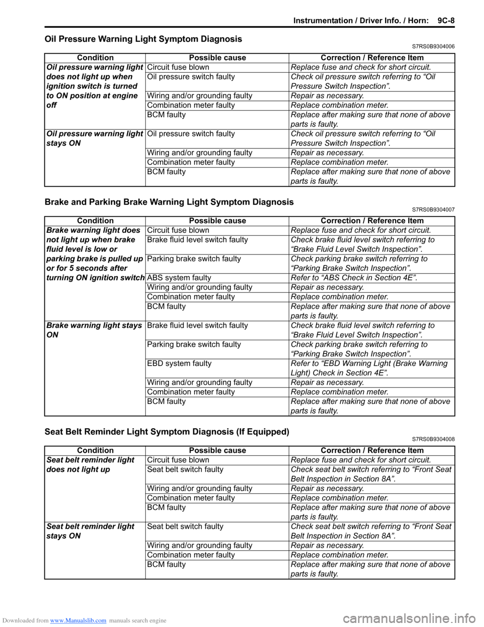
Oil Pressure Warning Light Symptom DiagnosisS7RS0B9304006
Brake and Parking Brake Warning Light Symptom DiagnosisS7RS0B9304007
Seat Belt Reminder Light Symptom Diagnosis (If Equipped)S7RS0B9304008
Condition Possible cause Correction / Reference Item
Oil pressure warning light
does not light up when
ignition switch is turned
to ON position at engine
off Circuit fuse blown
Replace fuse and check for short circuit.
Oil pressure switch faulty Check oil pressure switch referring to “Oil
Pressure Switch Inspection”.
Wiring and/or grounding faulty Repair as necessary.
Combination meter faulty Replace combination meter.
BCM faulty Replace after making sure that none of above
parts is faulty.
Oil pressure warning light
stays ON Oil pressure switch faulty
Check oil pressure switch referring to “Oil
Pressure Switch Inspection”.
Wiring and/or grounding faulty Repair as necessary.
Combination meter faulty Replace combination meter.
BCM faulty Replace after making sure that none of above
parts is faulty.
ConditionPossible cause Correction / Reference Item
Brake warning light does
not light up when brake
fluid level is low or
parking brake is pulled up
or for 5 seconds after
turning ON ignition switch Circuit fuse blown
Replace fuse and check for short circuit.
Brake fluid level switch faulty Check brake fluid level switch referring to
“Brake Fluid Level Switch Inspection”.
Parking brake switch faulty Check parking brake switch referring to
“Parking Brake Switch Inspection”.
ABS system faulty Refer to “ABS Check in Section 4E”.
Wiring and/or grounding faulty Repair as necessary.
Combination meter faulty Replace combination meter.
BCM faulty Replace after making sure that none of above
parts is faulty.
Brake warning light stays
ON Brake fluid level switch faulty
Check brake fluid level switch referring to
“Brake Fluid Level Switch Inspection”.
Parking brake switch faulty Check parking brake switch referring to
“Parking Brake Switch Inspection”.
EBD system faulty Refer to “EBD Warning Light (Brake Warning
Light) Check in Section 4E”.
Wiring and/or grounding faulty Repair as necessary.
Combination meter faulty Replace combination meter.
BCM faulty Replace after making sure that none of above
parts is faulty.
ConditionPossible cause Correction / Reference Item
Seat belt reminder light
does not light up Circuit fuse blown
Replace fuse and check for short circuit.
Seat belt switch faulty Check seat belt switch referring to “Front Seat
Belt Inspection in Section 8A”.
Wiring and/or grounding faulty Repair as necessary.
Combination meter faulty Replace combination meter.
BCM faulty Replace after making sure that none of above
parts is faulty.
Seat belt reminder light
stays ON Seat belt switch faulty
Check seat belt switch referring to “Front Seat
Belt Inspection in Section 8A”.
Wiring and/or grounding faulty Repair as necessary.
Combination meter faulty Replace combination meter.
BCM faulty Replace after making sure that none of above
parts is faulty.
Page 1311 of 1496

Downloaded from www.Manualslib.com manuals search engine Instrumentation / Driver Info. / Horn: 9C-16
Oil Pressure Switch InspectionS7RS0B9306007
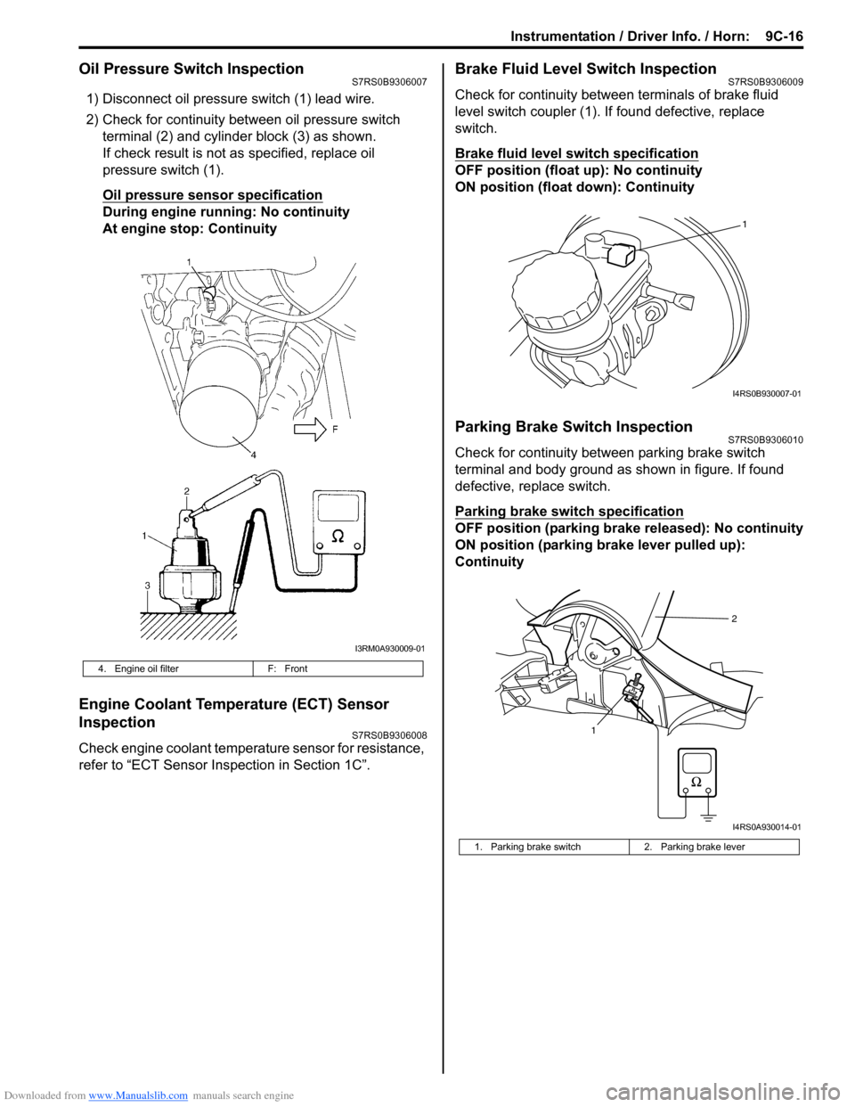
1) Disconnect oil pressure switch (1) lead wire.
2) Check for continuity between oil pressure switch terminal (2) and cylinder block (3) as shown.
If check result is not as specified, replace oil
pressure switch (1).
Oil pressure sensor specification
During engine running: No continuity
At engine stop: Continuity
Engine Coolant Temperature (ECT) Sensor
Inspection
S7RS0B9306008
Check engine coolant temperat ure sensor for resistance,
refer to “ECT Sensor Inspection in Section 1C”.
Brake Fluid Level Switch InspectionS7RS0B9306009
Check for continuity between terminals of brake fluid
level switch coupler (1). If found defective, replace
switch.
Brake fluid level switch specification
OFF position (float up): No continuity
ON position (float down): Continuity
Parking Brake Switch InspectionS7RS0B9306010
Check for continuity between parking brake switch
terminal and body ground as shown in figure. If found
defective, replace switch.
Parking brake switch specification
OFF position (parking brake released): No continuity
ON position (parking brake lever pulled up):
Continuity
4. Engine oil filter F: Front
I3RM0A930009-01
1. Parking brake switch 2. Parking brake lever
1
I4RS0B930007-01
12
I4RS0A930014-01