Tach SUZUKI SWIFT 2008 2.G Service Repair Manual
[x] Cancel search | Manufacturer: SUZUKI, Model Year: 2008, Model line: SWIFT, Model: SUZUKI SWIFT 2008 2.GPages: 1496, PDF Size: 34.44 MB
Page 696 of 1496
Downloaded from www.Manualslib.com manuals search engine 5A-52 Automatic Transmission/Transaxle:
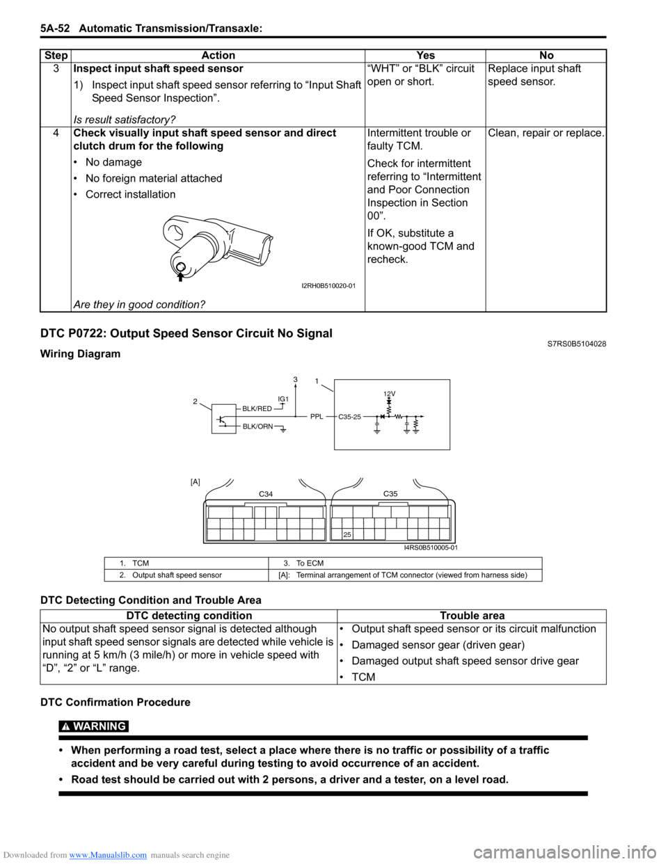
DTC P0722: Output Speed Sensor Circuit No SignalS7RS0B5104028
Wiring Diagram
DTC Detecting Condition and Trouble Area
DTC Confirmation Procedure
WARNING!
• When performing a road test, select a place where there is no traffic or possibility of a traffic
accident and be very careful during testing to avoid occurrence of an accident.
• Road test should be carried out with 2 persons, a driver and a tester, on a level road.
3 Inspect input shaft speed sensor
1) Inspect input shaft speed sensor referring to “Input Shaft
Speed Sensor Inspection”.
Is result satisfactory? “WHT” or “BLK” circuit
open or short.
Replace input shaft
speed sensor.
4 Check visually input shaft speed sensor and direct
clutch drum for the following
• No damage
• No foreign material attached
• Correct installation
Are they in good condition? Intermittent trouble or
faulty TCM.
Check for intermittent
referring to “Intermittent
and Poor Connection
Inspection in Section
00”.
If OK, substitute a
known-good TCM and
recheck.
Clean, repair or replace.
Step Action Yes No
I2RH0B510020-01
1. TCM
3. To ECM
2. Output shaft speed sensor [A]: Terminal arrangement of TCM connector (viewed from harness side)
DTC detecting condition Trouble area
No output shaft speed sensor signal is detected although
input shaft speed sensor signal s are detected while vehicle is
running at 5 km/h (3 mile/h) or more in vehicle speed with
“D”, “2” or “L” range. • Output shaft speed sensor or its circuit malfunction
• Damaged sensor gear (driven gear)
• Damaged output shaft speed sensor drive gear
•TCM
IG112V
PPLC35-25
2
C34
25
C35
[A]
1
BLK/RED
BLK/ORN
3
I4RS0B510005-01
Page 736 of 1496
Downloaded from www.Manualslib.com manuals search engine 5A-92 Automatic Transmission/Transaxle:
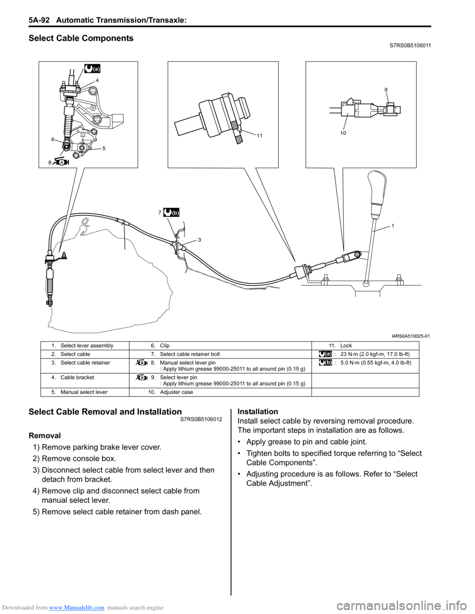
Select Cable ComponentsS7RS0B5106011
Select Cable Removal and InstallationS7RS0B5106012
Removal
1) Remove parking brake lever cover.
2) Remove console box.
3) Disconnect select cable from select lever and then detach from bracket.
4) Remove clip and disconnect select cable from manual select lever.
5) Remove select cable retainer from dash panel. Installation
Install select cable by reversing removal procedure.
The important steps in inst
allation are as follows.
• Apply grease to pin and cable joint.
• Tighten bolts to specified torque referring to “Select Cable Components”.
• Adjusting procedure is as follows. Refer to “Select Cable Adjustment”.
(a)
11
3
10
9
6
8 4
5
(b)
7
1
I4RS0A510025-01
1. Select lever assembly
6. Clip 11. Lock
2. Select cable 7. Select cable retainer bolt : 23 N⋅m (2.0 kgf-m, 17.0 lb-ft)
3. Select cable retainer 8. Manual select lever pin
: Apply lithium grease 99000-25011 to all around pin (0.15 g) :5.0 N
⋅m (0.55 kgf-m, 4.0 lb-ft)
4. Cable bracket 9. Select lever pin
: Apply lithium grease 99000-25011 to all around pin (0.15 g)
5. Manual select lever 10. Adjuster case
Page 738 of 1496
Downloaded from www.Manualslib.com manuals search engine 5A-94 Automatic Transmission/Transaxle:
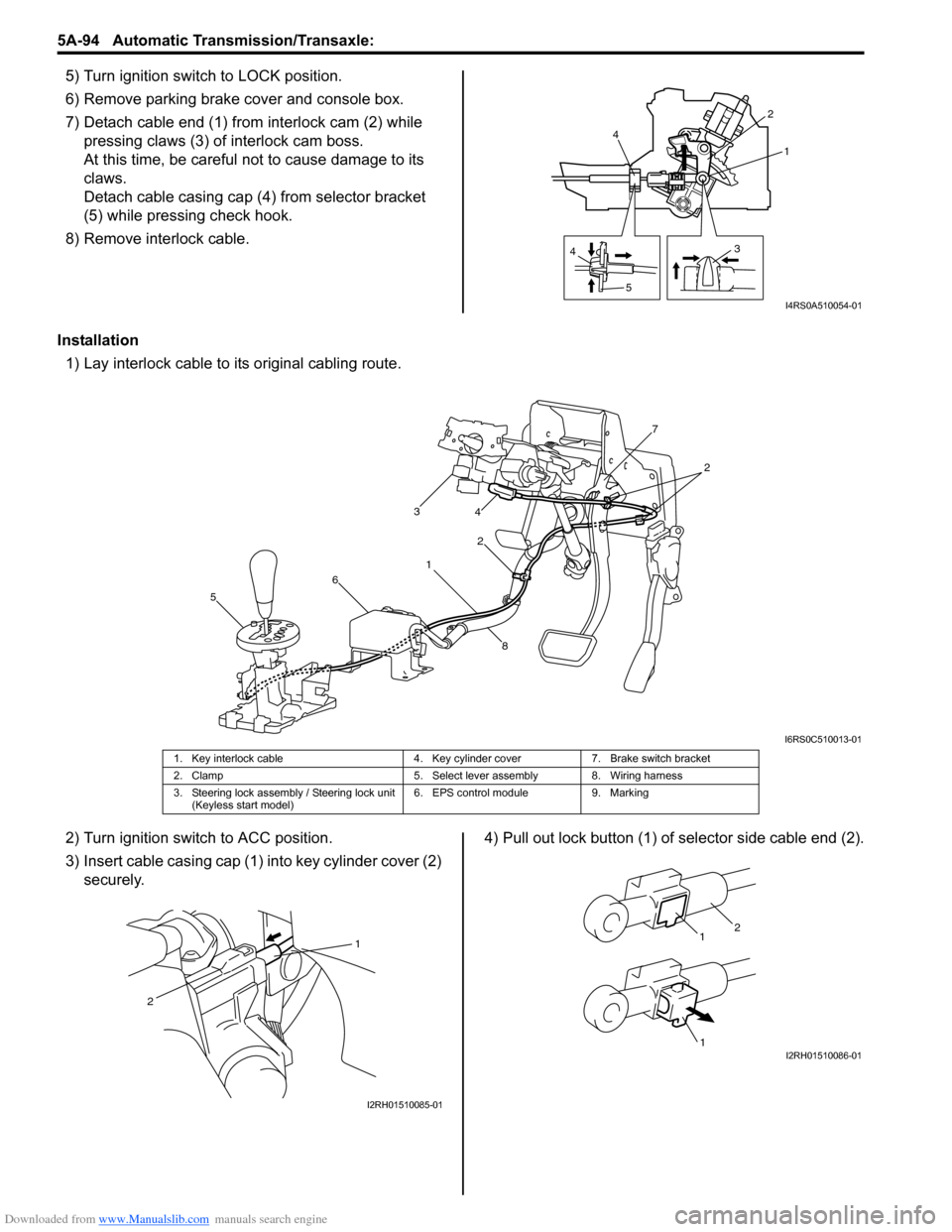
5) Turn ignition switch to LOCK position.
6) Remove parking brake cover and console box.
7) Detach cable end (1) from interlock cam (2) while
pressing claws (3) of interlock cam boss.
At this time, be careful no t to cause damage to its
claws.
Detach cable casing cap (4 ) from selector bracket
(5) while pressing check hook.
8) Remove interlock cable.
Installation 1) Lay interlock cable to its original cabling route.
2) Turn ignition switch to ACC position.
3) Insert cable casing cap (1) into key cylinder cover (2) securely. 4) Pull out lock button (1) of selector side cable end (2).
4
5 31
2
4
I4RS0A510054-01
1 2
3
4
5 6 7
8
2
I6RS0C510013-01
1. Key interlock cable 4. Key cylinder cover7. Brake switch bracket
2. Clamp 5. Select lever assembly 8. Wiring harness
3. Steering lock assembly / Steering lock unit (Keyless start model) 6. EPS control module
9. Marking
1
2
I2RH01510085-01
1
1
2
I2RH01510086-01
Page 750 of 1496
Downloaded from www.Manualslib.com manuals search engine 5A-106 Automatic Transmission/Transaxle:
Automatic Transaxle Unit Dismounting and
Remounting
S7RS0B5106031
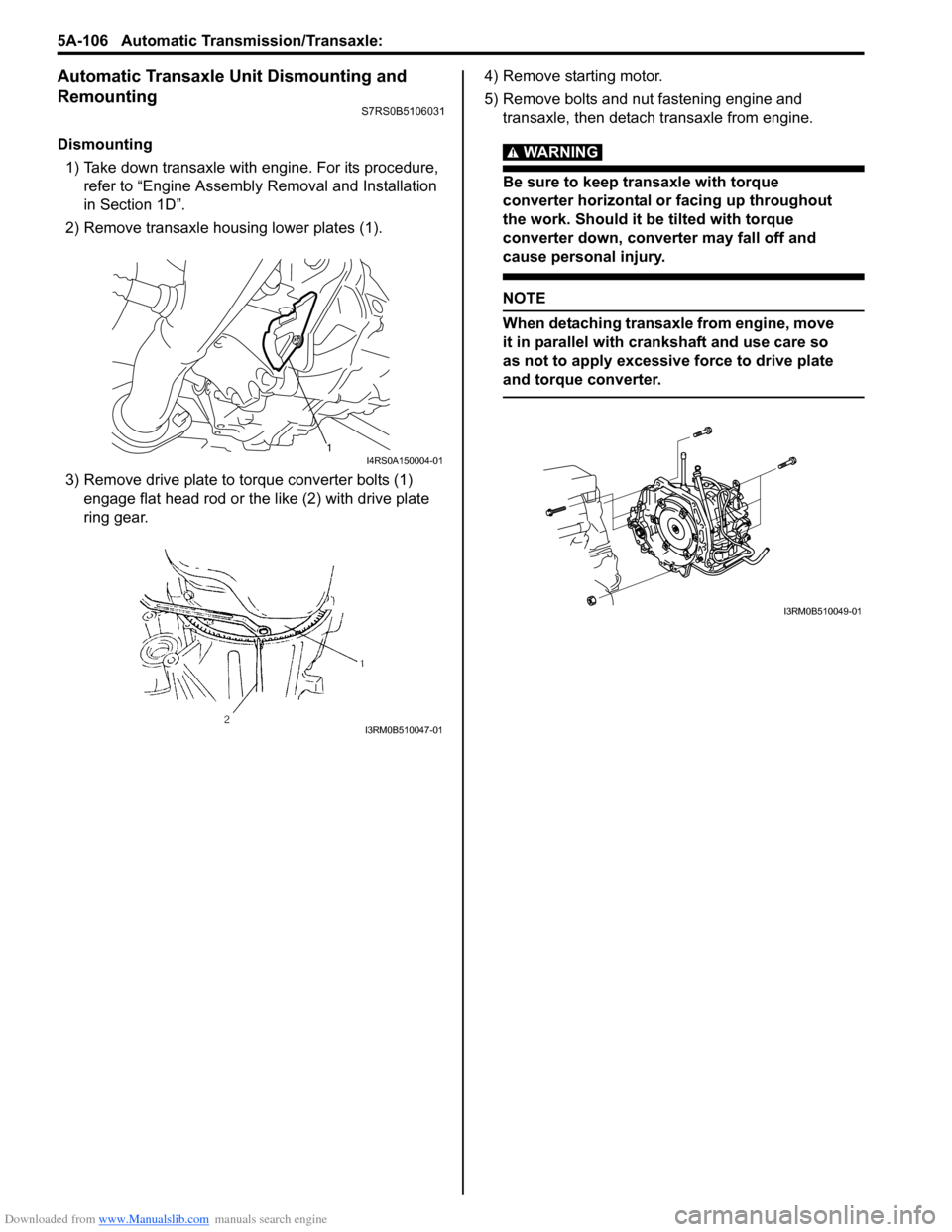
Dismounting1) Take down transaxle with engine. For its procedure, refer to “Engine Assembly Removal and Installation
in Section 1D”.
2) Remove transaxle housing lower plates (1).
3) Remove drive plate to torque converter bolts (1) engage flat head rod or the like (2) with drive plate
ring gear. 4) Remove starting motor.
5) Remove bolts and nut fastening engine and
transaxle, then detach transaxle from engine.WARNING!
Be sure to keep transaxle with torque
converter horizontal or facing up throughout
the work. Should it be tilted with torque
converter down, converter may fall off and
cause personal injury.
NOTE
When detaching transaxle from engine, move
it in parallel with cranks haft and use care so
as not to apply excessive force to drive plate
and torque converter.
1I4RS0A150004-01
I3RM0B510047-01
I3RM0B510049-01
Page 751 of 1496
Downloaded from www.Manualslib.com manuals search engine Automatic Transmission/Transaxle: 5A-107
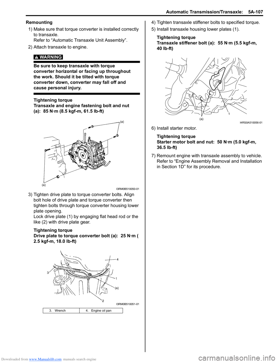
Remounting1) Make sure that torque converter is installed correctly to transaxle.
Refer to “Automatic Transaxle Unit Assembly”.
2) Attach transaxle to engine.
WARNING!
Be sure to keep transaxle with torque
converter horizontal or facing up throughout
the work. Should it be tilted with torque
converter down, converter may fall off and
cause personal injury.
Tightening torque
Transaxle and engine fastening bolt and nut
(a): 85 N·m (8.5 kgf-m, 61.5 lb-ft)
3) Tighten drive plate to torque converter bolts. Align bolt hole of drive plate and torque converter then
tighten bolts through torque converter housing lower
plate opening.
Lock drive plate (1) by engaging flat head rod or the
like (2) with drive plate gear.
Tightening torque
Drive plate to torque converter bolt (a): 25 N·m (
2.5 kgf-m, 18.0 lb-ft) 4) Tighten transaxle stiffener bolts to specified torque.
5) Install transaxle housing lower plates (1).
Tightening torque
Transaxle stiffener bolt (a): 55 N·m (5.5 kgf-m,
40 lb-ft)
6) Install starter motor. Tightening torque
Starter motor bolt and nut: 50 N·m (5.0 kgf-m,
36.5 lb-ft)
7) Remount engine with transaxle assembly to vehicle. Refer to “Engine Assembly Removal and Installation
in Section 1D” for its procedure.
3. Wrench 4. Engine oil pan
I3RM0B510050-01
I3RM0B510051-01
1
(a)
I4RS0A510056-01
Page 768 of 1496
Downloaded from www.Manualslib.com manuals search engine 5A-124 Automatic Transmission/Transaxle:
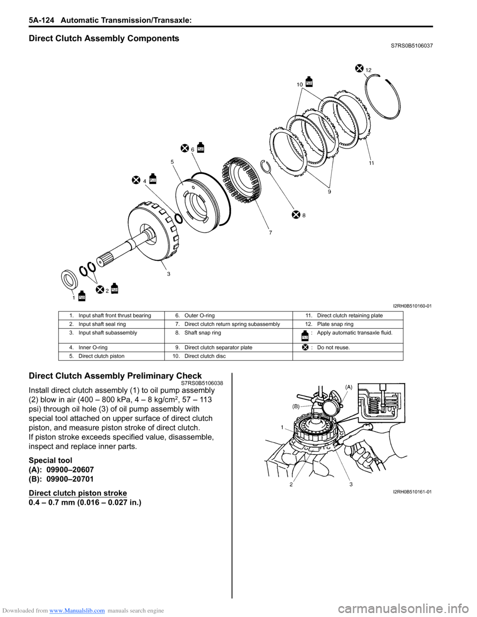
Direct Clutch Assembly ComponentsS7RS0B5106037
Direct Clutch Assembly Preliminary CheckS7RS0B5106038
Install direct clutch assembly (1) to oil pump assembly
(2) blow in air (400 – 800 kPa, 4 – 8 kg/cm2, 57 – 113
psi) through oil hole (3) of oil pump assembly with
special tool attached on uppe r surface of direct clutch
piston, and measure piston stroke of direct clutch.
If piston stroke exceeds sp ecified value, disassemble,
inspect and replace inner parts.
Special tool
(A): 09900–20607
(B): 09900–20701
Direct clutch piston stroke
0.4 – 0.7 mm (0.016 – 0.027 in.)
I2RH0B510160-01
1. Input shaft front thrust bearing 6. Outer O-ring 11. Direct clutch retaining plate
2. Input shaft seal ring 7. Direct clutch return spring subassembly 12. Plate snap ring
3. Input shaft subassembly 8. Shaft snap ring : Apply automatic transaxle fluid.
4. Inner O-ring 9. Direct clutch separator plate : Do not reuse.
5. Direct clutch piston 10. Direct clutch disc
I2RH0B510161-01
Page 773 of 1496
Downloaded from www.Manualslib.com manuals search engine Automatic Transmission/Transaxle: 5A-129
Forward and Reverse Clutch Assembly
Preliminary Check
S7RS0B5106042
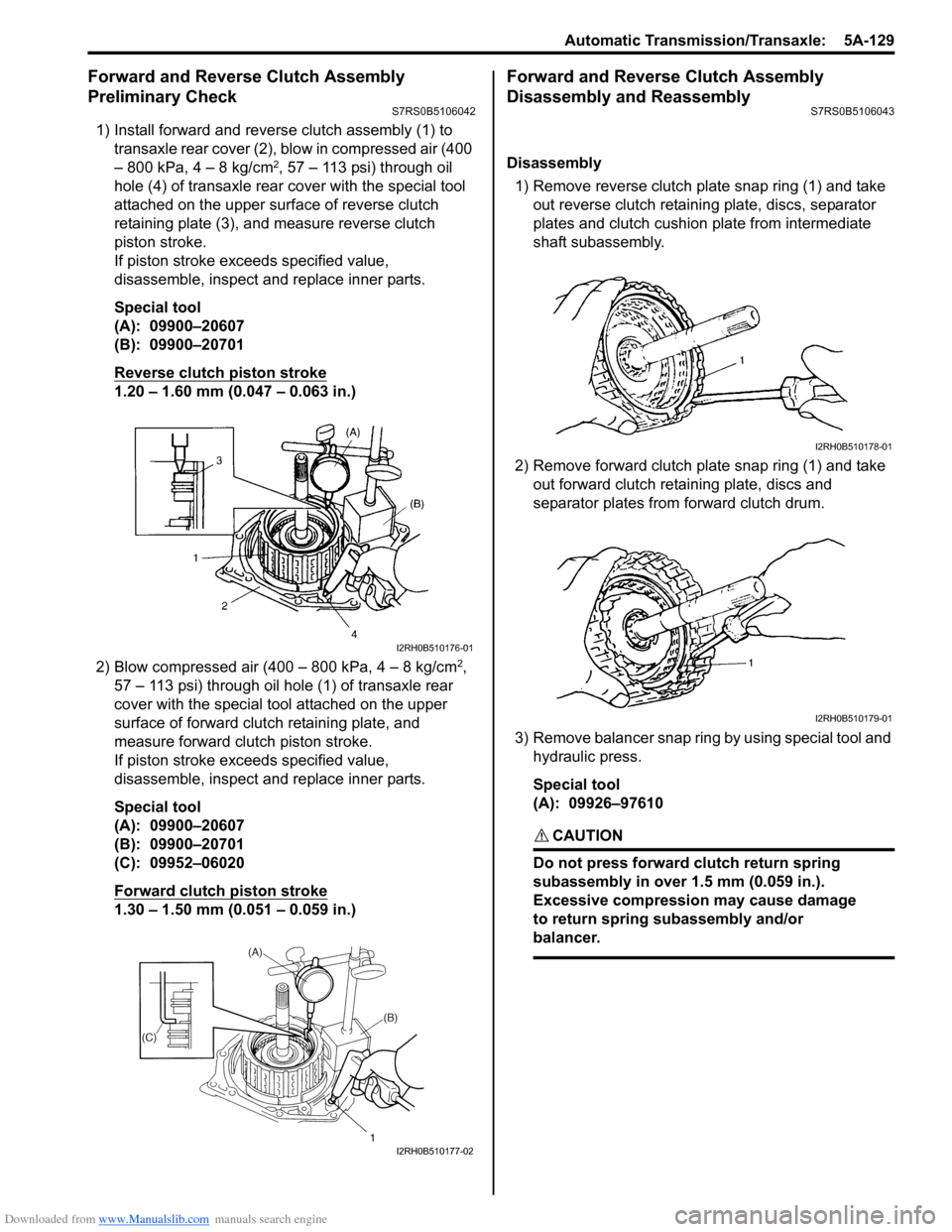
1) Install forward and reverse clutch assembly (1) to
transaxle rear cover (2), blow in compressed air (400
– 800 kPa, 4 – 8 kg/cm
2, 57 – 113 psi) through oil
hole (4) of transaxle rear cover with the special tool
attached on the upper surf ace of reverse clutch
retaining plate (3), and measure reverse clutch
piston stroke.
If piston stroke exce eds specified value,
disassemble, inspect and replace inner parts.
Special tool
(A): 09900–20607
(B): 09900–20701
Reverse clutch piston stroke
1.20 – 1.60 mm (0.047 – 0.063 in.)
2) Blow compressed air (400 – 800 kPa, 4 – 8 kg/cm
2,
57 – 113 psi) through oil hole (1) of transaxle rear
cover with the special tool attached on the upper
surface of forward clutch retaining plate, and
measure forward clutch piston stroke.
If piston stroke exce eds specified value,
disassemble, inspect and replace inner parts.
Special tool
(A): 09900–20607
(B): 09900–20701
(C): 09952–06020
Forward clutch piston stroke
1.30 – 1.50 mm (0.051 – 0.059 in.)
Forward and Reverse Clutch Assembly
Disassembly and Reassembly
S7RS0B5106043
Disassembly
1) Remove reverse clutch plate snap ring (1) and take out reverse clutch retaini ng plate, discs, separator
plates and clutch cushion plate from intermediate
shaft subassembly.
2) Remove forward clutch plate snap ring (1) and take out forward clutch retaining plate, discs and
separator plates from forward clutch drum.
3) Remove balancer snap ring by using special tool and hydraulic press.
Special tool
(A): 09926–97610
CAUTION!
Do not press forward clutch return spring
subassembly in over 1.5 mm (0.059 in.).
Excessive compression may cause damage
to return spring subassembly and/or
balancer.
I2RH0B510176-01
I2RH0B510177-02
I2RH0B510178-01
I2RH0B510179-01
Page 781 of 1496
Downloaded from www.Manualslib.com manuals search engine Automatic Transmission/Transaxle: 5A-137
Reassembly
Reverse disassembly procedure for assembly, noting the
following points.
• Use new seal rings and O-rings. Apply A/T fluid to seal rings and O-rings before installation.
• Tighten rear cover plugs to specified torque.
Tightening torque
Rear cover plug: 7.5 N·m (0.75 kgf-m, 5.5 lb-ft)
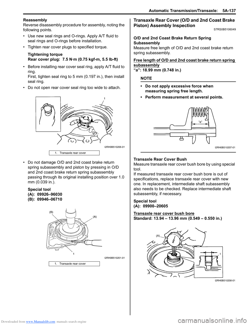
• Before installing rear cover seal ring, apply A/T fluid to ring.
First, tighten seal ring to 5 mm (0.197 in.), then install
seal ring.
• Do not open rear cover seal ring too wide to attach.
• Do not damage O/D and 2nd coast brake return spring subassembly and piston by pressing in O/D
and 2nd coast brake return spring subassembly
passing through its original installing position over 1.0
mm (0.039 in.).
Special tool
(A): 09926–96030
(B): 09946–06710Transaxle Rear Cover (O/D and 2nd Coast Brake
Piston) Assembly Inspection
S7RS0B5106049
O/D and 2nd Coast Brake Return Spring
Subassembly
Measure free length of O/D and 2nd coast brake return
spring subassembly.
Free length of O/D and 2nd coast brake return spring
subassembly
“a”: 18.99 mm (0.748 in.)
NOTE
• Do not apply excessive force when measuring spring free length.
• Perform measurement at several points.
Transaxle Rear Cover Bush
Measure transaxle rear cover bush bore by using special
tool.
If measured transaxle rear cover bush bore is out of
specifications, replace transaxle rear cover with new
one. In replacement, inte rmediate shaft subassembly
also needs to be checked. Replace intermediate shaft
subassembly, if necessary.
Special tool
(A): 09900–20605
Transaxle rear cover bush bore
Standard: 13.94 – 13.96 mm (0.549 – 0.550 in.)
1. Transaxle rear cover
1. Transaxle rear cover
I2RH0B510206-01
I2RH0B510201-01
I2RH0B510207-01
I2RH0B510208-01
Page 795 of 1496
Downloaded from www.Manualslib.com manuals search engine Automatic Transmission/Transaxle: 5A-151
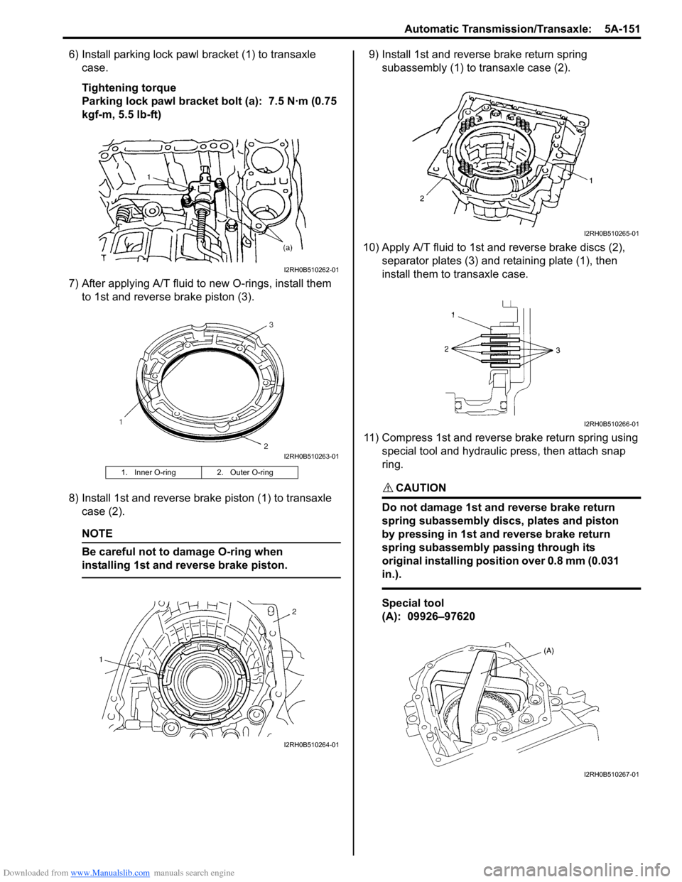
6) Install parking lock pawl bracket (1) to transaxle
case.
Tightening torque
Parking lock pawl bracket bolt (a): 7.5 N·m (0.75
kgf-m, 5.5 lb-ft)
7) After applying A/T fluid to new O-rings, install them to 1st and reverse brake piston (3).
8) Install 1st and reverse brake piston (1) to transaxle case (2).
NOTE
Be careful not to damage O-ring when
installing 1st and reverse brake piston.
9) Install 1st and reverse brake return spring subassembly (1) to transaxle case (2).
10) Apply A/T fluid to 1st and reverse brake discs (2), separator plates (3) and retaining plate (1), then
install them to transaxle case.
11) Compress 1st and reverse brake return spring using special tool and hydraulic press, then attach snap
ring.
CAUTION!
Do not damage 1st and reverse brake return
spring subassembly discs, plates and piston
by pressing in 1st and reverse brake return
spring subassembly passing through its
original installing position over 0.8 mm (0.031
in.).
Special tool
(A): 09926–97620
1. Inner O-ring 2. Outer O-ring
I2RH0B510262-01
I2RH0B510263-01
I2RH0B510264-01
I2RH0B510265-01
I2RH0B510266-01
I2RH0B510267-01
Page 802 of 1496
Downloaded from www.Manualslib.com manuals search engine 5A-158 Automatic Transmission/Transaxle:
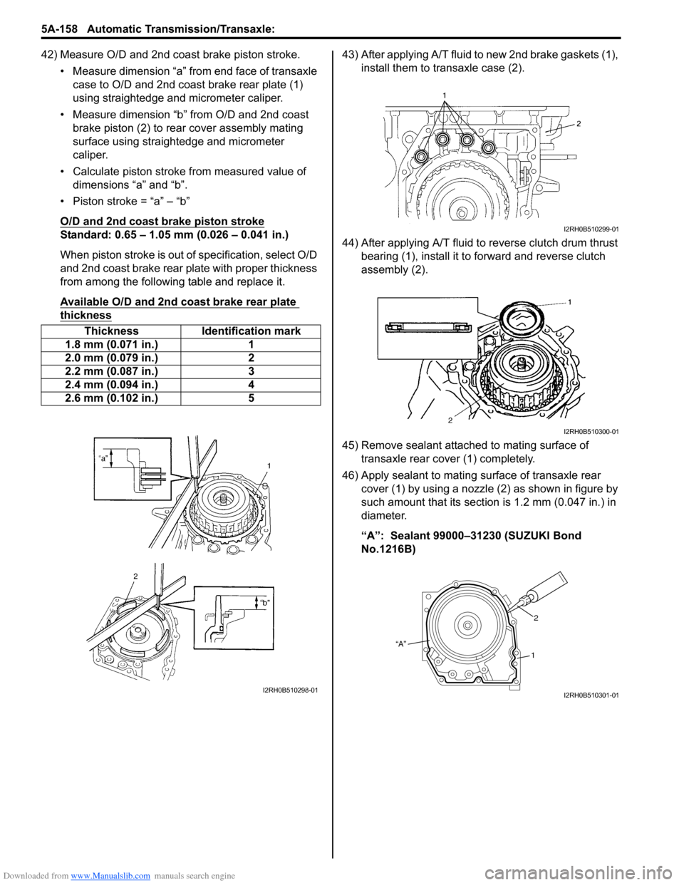
42) Measure O/D and 2nd coast brake piston stroke.• Measure dimension “a” from end face of transaxle case to O/D and 2nd coast brake rear plate (1)
using straightedge and micrometer caliper.
• Measure dimension “b” from O/D and 2nd coast brake piston (2) to rear cover assembly mating
surface using straightedge and micrometer
caliper.
• Calculate piston stroke from measured value of dimensions “a” and “b”.
• Piston stroke = “a” – “b”
O/D and 2nd coast brake piston stroke
Standard: 0.65 – 1.05 mm (0.026 – 0.041 in.)
When piston stroke is out of specification, select O/D
and 2nd coast brake rear plate with proper thickness
from among the following table and replace it.
Available O/D and 2nd coast brake rear plate
thickness
43) After applying A/T fluid to new 2nd brake gaskets (1), install them to transaxle case (2).
44) After applying A/T fluid to reverse clutch drum thrust bearing (1), install it to forward and reverse clutch
assembly (2).
45) Remove sealant attached to mating surface of transaxle rear cover (1) completely.
46) Apply sealant to mating surface of transaxle rear cover (1) by using a nozzle (2) as shown in figure by
such amount that its section is 1.2 mm (0.047 in.) in
diameter.
“A”: Sealant 99000–31230 (SUZUKI Bond
No.1216B)
Thickness Identification mark
1.8 mm (0.071 in.) 1
2.0 mm (0.079 in.) 2
2.2 mm (0.087 in.) 3
2.4 mm (0.094 in.) 4
2.6 mm (0.102 in.) 5
I2RH0B510298-01
I2RH0B510299-01
I2RH0B510300-01
“A” 2
1
I2RH0B510301-01