Vehicle speed sensor SUZUKI SWIFT 2008 2.G Service Repair Manual
[x] Cancel search | Manufacturer: SUZUKI, Model Year: 2008, Model line: SWIFT, Model: SUZUKI SWIFT 2008 2.GPages: 1496, PDF Size: 34.44 MB
Page 570 of 1496
Downloaded from www.Manualslib.com manuals search engine 4E-31 ABS:
2) Bleed air from brake system referring to “Air Bleeding of Brake System in Section 4A”.
3) Check each installed part for fluid leakage and perform “ABS Hydraulic Un it Operation Check”.
NOTE
For new ABS hydraulic unit / control module
assembly, if “ABS Hydraulic Unit Operation
Check” has not been performed, ABS
warning light may flash when ignition switch
is turned ON position.
Accordingly preform “ABS Hydraulic Unit
Operation Check” to stop flashing of ABS
warning light.
Front / Rear Wheel Speed Sensor On-Vehicle
Inspection
S7RS0B4506005
Output Voltage Inspection
1) Disconnect negative cable from battery.
2) Hoist vehicle a little.
3) Disconnect wheel speed sensor connector.
4) Disconnect wheel speed grommet from vehicle body.
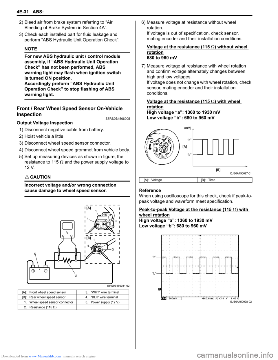
5) Set up measuring devices as shown in figure, the resistance to 115 Ω and the power supply voltage to
12 V.
CAUTION!
Incorrect voltage and/or wrong connection
cause damage to wheel speed sensor.
6) Measure voltage at resistance without wheel rotation.
If voltage is out of specification, check sensor,
mating encoder and their installation conditions.
Voltage at the resistance (115
Ω) without wheel
rotation
680 to 960 mV
7) Measure voltage at resistance with wheel rotation and confirm voltage alternately changes between
high and low voltages.
If voltage does not change with wheel rotation, check
sensor, mating encoder and their installation
conditions.
Voltage at the resistance (115
Ω) with wheel
rotation
High voltage “a”: 1360 to 1930 mV
Low voltage “b”: 680 to 960 mV
Reference
When using oscilloscope for this check, check if peak-to-
peak voltage and waveform meet specification.
Peak-to-peak Voltage at the resistance (115
Ω) with
wheel rotation
High voltage “a”: 1360 to 1930 mV
Low voltage “b”: 680 to 960 mV
[A]: Front wheel speed sensor 3. “WHT” wire terminal
[B]: Rear wheel speed sensor 4. “BLK” wire terminal
1. Wheel speed sensor connector 5. Power supply (12 V)
2. Resistance (115 Ω )
V
2
5
41
3
43
1
[A]
[B]
I6RS0B460031-02
[A]: Voltage [B]: Time
I5JB0A450027-01
I5JB0A450028-02
Page 571 of 1496
Downloaded from www.Manualslib.com manuals search engine ABS: 4E-32
Front Wheel Speed Sensor Removal and
Installation
S7RS0B4506006
Removal1) Disconnect negative cable from battery.
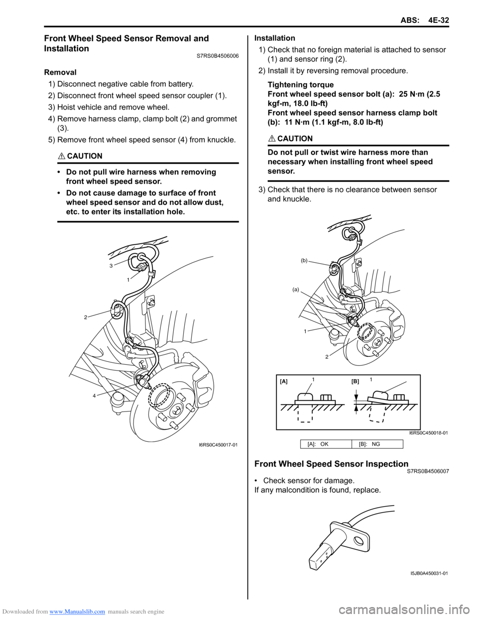
2) Disconnect front wheel speed sensor coupler (1).
3) Hoist vehicle and remove wheel.
4) Remove harness clamp, clamp bolt (2) and grommet (3).
5) Remove front wheel speed sensor (4) from knuckle.
CAUTION!
• Do not pull wire ha rness when removing
front wheel speed sensor.
• Do not cause damage to surface of front wheel speed sensor and do not allow dust,
etc. to enter its installation hole.
Installation
1) Check that no foreign material is attached to sensor (1) and sensor ring (2).
2) Install it by reversing removal procedure.
Tightening torque
Front wheel speed sensor bolt (a): 25 N·m (2.5
kgf-m, 18.0 lb-ft)
Front wheel speed sensor harness clamp bolt
(b): 11 N·m (1.1 kgf-m, 8.0 lb-ft)
CAUTION!
Do not pull or twist wire harness more than
necessary when installing front wheel speed
sensor.
3) Check that there is no clearance between sensor
and knuckle.
Front Wheel Speed Sensor InspectionS7RS0B4506007
• Check sensor for damage.
If any malcondition is found, replace.
3
1
2
4
I6RS0C450017-01[A]: OK [B]: NG
[A][B]
11
(a)
(b)
1
2
I6RS0C450018-01
I5JB0A450031-01
Page 572 of 1496
Downloaded from www.Manualslib.com manuals search engine 4E-33 ABS:
Rear Wheel Speed Sensor Removal and
Installation
S7RS0B4506008
Removal1) Disconnect negative (–) cable from battery.
2) Remove quarter inner trim to brake referring to “Floor Carpet Removal a nd Installation in Section
9H”.
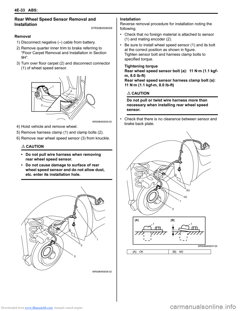
3) Turn over floor carpet (2) and disconnect connector (1) of wheel speed sensor.
4) Hoist vehicle and remove wheel.
5) Remove harness clamp (1) and clamp bolts (2).
6) Remove rear wheel speed sensor (3) from knuckle.
CAUTION!
• Do not pull wire harness when removing rear wheel speed sensor.
• Do not cause damage to surface of rear wheel speed sensor and do not allow dust,
etc. enter its installation hole.
Installation
Reverse removal procedure for installation noting the
following.
• Check that no foreign material is attached to sensor (1) and mating encoder (2).
• Be sure to install wheel speed sensor (1) and its bolt at the correct position as shown in figure.
Tighten sensor bolt and harness clamp bolts to
specified torque.
Tightening torque
Rear wheel speed sensor bolt (a): 11 N·m (1.1 kgf-
m, 8.0 lb-ft)
Rear wheel speed sensor harness clamp bolt (a):
11 N·m (1.1 kgf-m, 8.0 lb-ft)
CAUTION!
Do not pull or twist wire harness more than
necessary when installing rear wheel speed
sensor.
• Check that there is no clearance between sensor and brake back plate.
2
2
1
I6RS0B460035-02
3
2
1
I6RS0B460036-02
[A]: OK [B]: NG
1
(b)
[A][B]
11
(a)
2
I6RS0B460037-02
Page 573 of 1496
Downloaded from www.Manualslib.com manuals search engine ABS: 4E-34
Rear Wheel Speed Sensor InspectionS7RS0B4506009
Refer to “Front Wheel Speed Sensor Inspection” since
rear wheel speed sensor is the same as front wheel
speed sensor.
Front Wheel Encoder On-Vehicle InspectionS7RS0B4506010
Before inspect front wheel encoder, remove front drive
shaft or front wheel spindle referring to “Front Drive Shaft
Assembly Removal and Installation in Section 3A”.
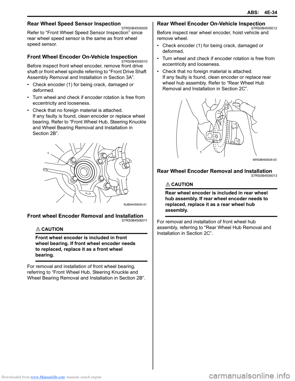
• Check encoder (1) for being crack, damaged or deformed.
• Turn wheel and check if encoder rotation is free from eccentricity and looseness.
• Check that no foreign material is attached. If any faulty is found, cl ean encoder or replace wheel
bearing. Refer to “Front Wheel Hub, Steering Knuckle
and Wheel Bearing Removal and Installation in
Section 2B”.
Front wheel Encoder Removal and InstallationS7RS0B4506011
CAUTION!
Front wheel encoder is included in front
wheel bearing. If front wheel encoder needs
to replaced, replace it as a front wheel
bearing.
For removal and installation of front wheel bearing,
referring to “Front Wheel Hub, Steering Knuckle and
Wheel Bearing Removal and Installation in Section 2B”.
Rear Wheel Encoder On-Vehicle InspectionS7RS0B4506012
Before inspect rear wheel encoder, hoist vehicle and
remove wheel.
• Check encoder (1) for being crack, damaged or deformed.
• Turn wheel and check if encoder rotation is free from eccentricity and looseness.
• Check that no foreign material is attached. If any faulty is found, clean encoder or replace rear
wheel hub assembly. Refer to “Rear Wheel Hub
Removal and Installati on in Section 2C”.
Rear Wheel Encoder Removal and InstallationS7RS0B4506013
CAUTION!
Rear wheel encoder is included in rear wheel
hub assembly. If rear wheel encoder needs to
replaced, replace it as a rear wheel hub
assembly.
For removal and installation of front wheel hub
assembly, referring to “Rear Wheel Hub Removal and
Installation in Section 2C”.
1
I5JB0A450034-01
1
I6RS0B460038-03
Page 576 of 1496
Downloaded from www.Manualslib.com manuals search engine 4F-2 Electronic Stability Program:
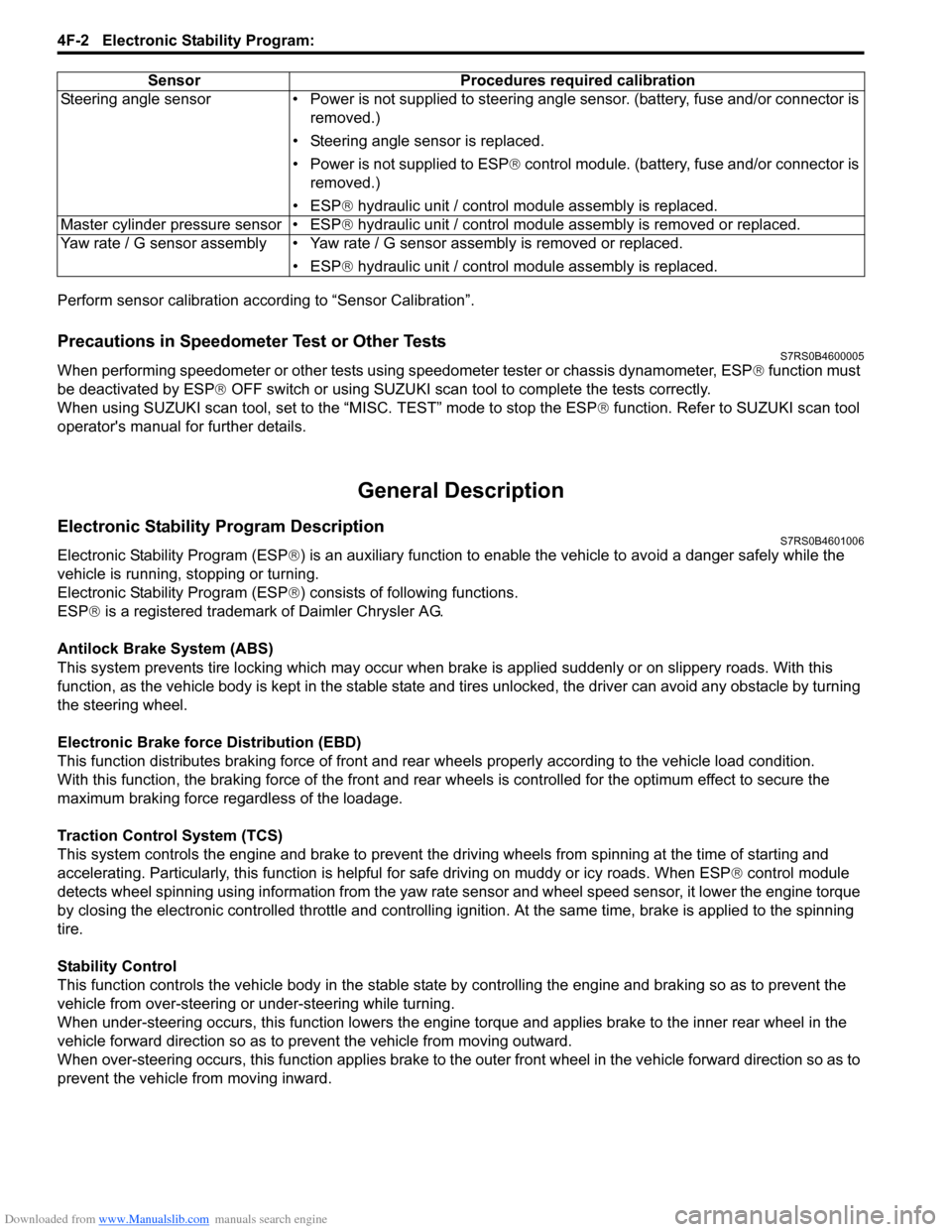
Perform sensor calibration according to “Sensor Calibration”.
Precautions in Speedometer Test or Other TestsS7RS0B4600005
When performing speedometer or other tests using speedometer tester or chassis dynamometer, ESP® function must
be deactivated by ESP ® OFF switch or using SUZUKI scan to ol to complete the tests correctly.
When using SUZUKI scan tool, set to the “MISC. TEST” mode to stop the ESP ® function. Refer to SUZUKI scan tool
operator's manual for further details.
General Description
Electronic Stability Program DescriptionS7RS0B4601006
Electronic Stability Program (ESP ®) is an auxiliary function to enable the vehicle to av oid a danger safely while the
vehicle is running, stopping or turning.
Electronic Stability Program (ESP ®) consists of following functions.
ESP ® is a registered trademark of Daimler Chrysler AG.
Antilock Brake System (ABS)
This system prevents tire locking which may occur when br ake is applied suddenly or on slippery roads. With this
function, as the vehicle body is kept in the stable state an d tires unlocked, the driver can avoid any obstacle by turning
the steering wheel.
Electronic Brake force Distribution (EBD)
This function distributes braking force of front and rear wheels properly according to the vehicle load condition.
With this function, the braking force of the front and rear wheels is controlled for the optimum effect to secure the
maximum braking force regardless of the loadage.
Traction Control System (TCS)
This system controls the engine and brake to prevent the dr iving wheels from spinning at the time of starting and
accelerating. Particularly, this fu nction is helpful for safe driving on muddy or icy roads. When ESP ® control module
detects wheel spinning using information from the yaw rate sensor and wheel speed sensor, it lower the engine torque
by closing the electronic controlled thro ttle and controlling ignition. At the same time, brake is applied to the spinning
tire.
Stability Control
This function controls the vehicle body in the stable state by controlling the engine and braking so as to prevent the
vehicle from over-steering or under-steering while turning.
When under-steering occurs, this function lowers the engine torque and applies brake to the inner rear wheel in the
vehicle forward direction so as to pr event the vehicle from moving outward.
When over-steering occurs, this function applies brake to the outer front wheel in the vehicle forward direction so as to
prevent the vehicle from moving inward. Sensor Procedures required calibration
Steering angle sensor • Power is not su pplied to steering angle sensor. (battery, fuse and/or connector is
removed.)
• Steering angle sensor is replaced.
• Power is not supplied to ESP ® control module. (battery, fuse and/or connector is
removed.)
• ESP® hydraulic unit / control module assembly is replaced.
Master cylinder pressure sensor • ESP® hydraulic unit / control module assembly is removed or replaced.
Yaw rate / G sensor assembly • Yaw rate / G sensor assembly is removed or replaced.
• ESP® hydraulic unit / control module assembly is replaced.
Page 577 of 1496
Downloaded from www.Manualslib.com manuals search engine Electronic Stability Program: 4F-3
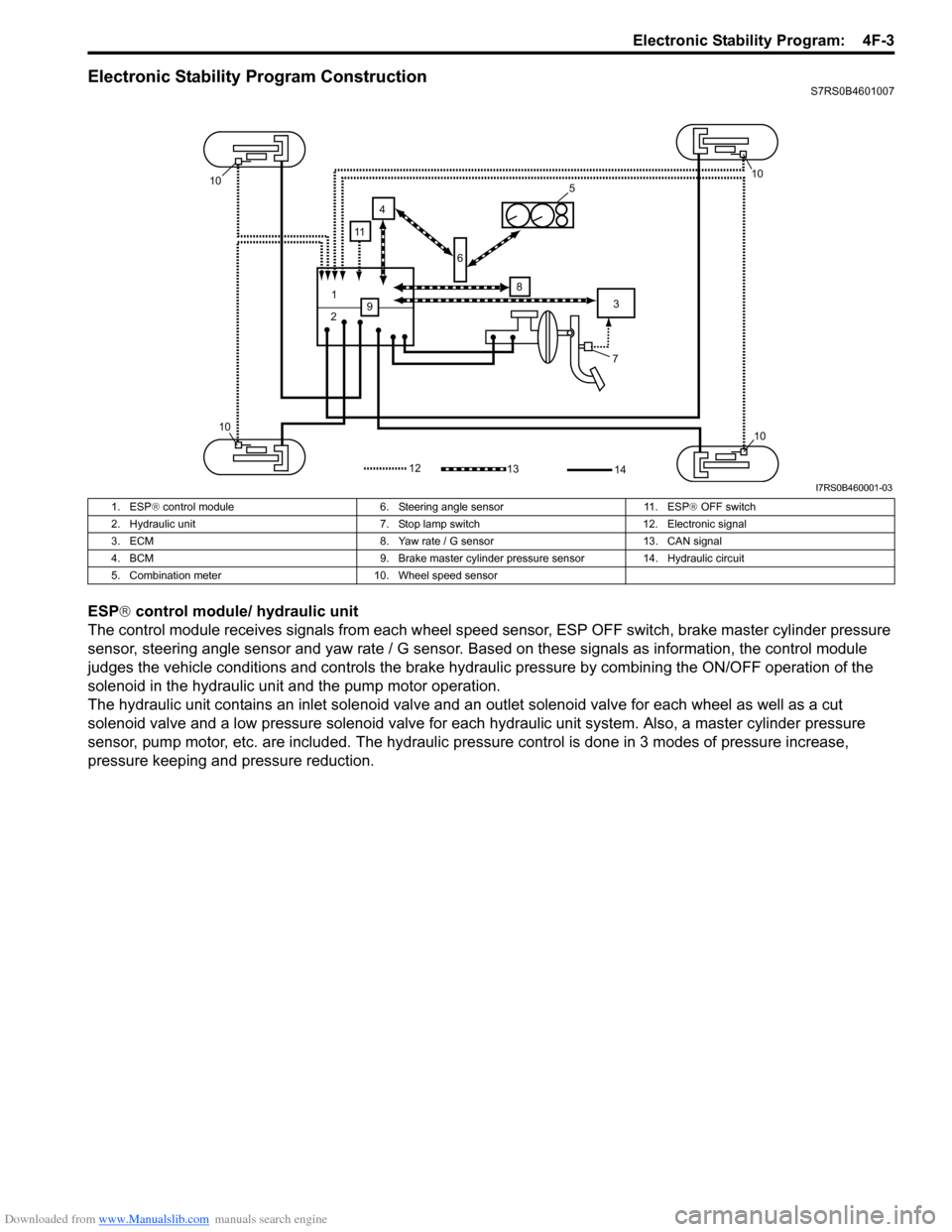
Electronic Stability Program ConstructionS7RS0B4601007
ESP® control module/ hydraulic unit
The control module receives signals from each wheel speed sensor, ESP O FF switch, brake master cylinder pressure
sensor, steering angle sensor and yaw rate / G sensor. Ba sed on these signals as information, the control module
judges the vehicle conditions and controls the brake hydraulic pressure by combining the ON/OFF operation of the
solenoid in the hydraulic unit and the pump motor operation.
The hydraulic unit contains an inlet so lenoid valve and an outlet solenoid valve for each wheel as well as a cut
solenoid valve and a low pressure solenoid valve for each hydraulic unit system. Also, a master cylinder pressure
sensor, pump motor, etc. are included. The hydraulic pre ssure control is done in 3 modes of pressure increase,
pressure keeping and pressure reduction.
7
1
2 3
4
5
6
8
9
10
1010
10
1312
11
14
I7RS0B460001-03
1. ESP ® control module 6. Steering angle sensor 11. ESP ® OFF switch
2. Hydraulic unit 7. Stop lamp switch 12. Electronic signal
3. ECM 8. Yaw rate / G sensor 13. CAN signal
4. BCM 9. Brake master cylinder pre ssure sensor 14. Hydraulic circuit
5. Combination meter 10. Wheel speed sensor
Page 579 of 1496
Downloaded from www.Manualslib.com manuals search engine Electronic Stability Program: 4F-5
Yaw rate / G sensor
The yaw rate / G sensor consists of the yaw rate (angular velocity in the vehicle turning direction) sensor and right-left
G (acceleration in right-left direction) sensor and is mounted to the P/S controller B/K at the lower part of the center
console. It detects the angular velocity in the vehicle turn ing direction and movement in the right-left direction, and
then it sends that information to ESP ® control module.
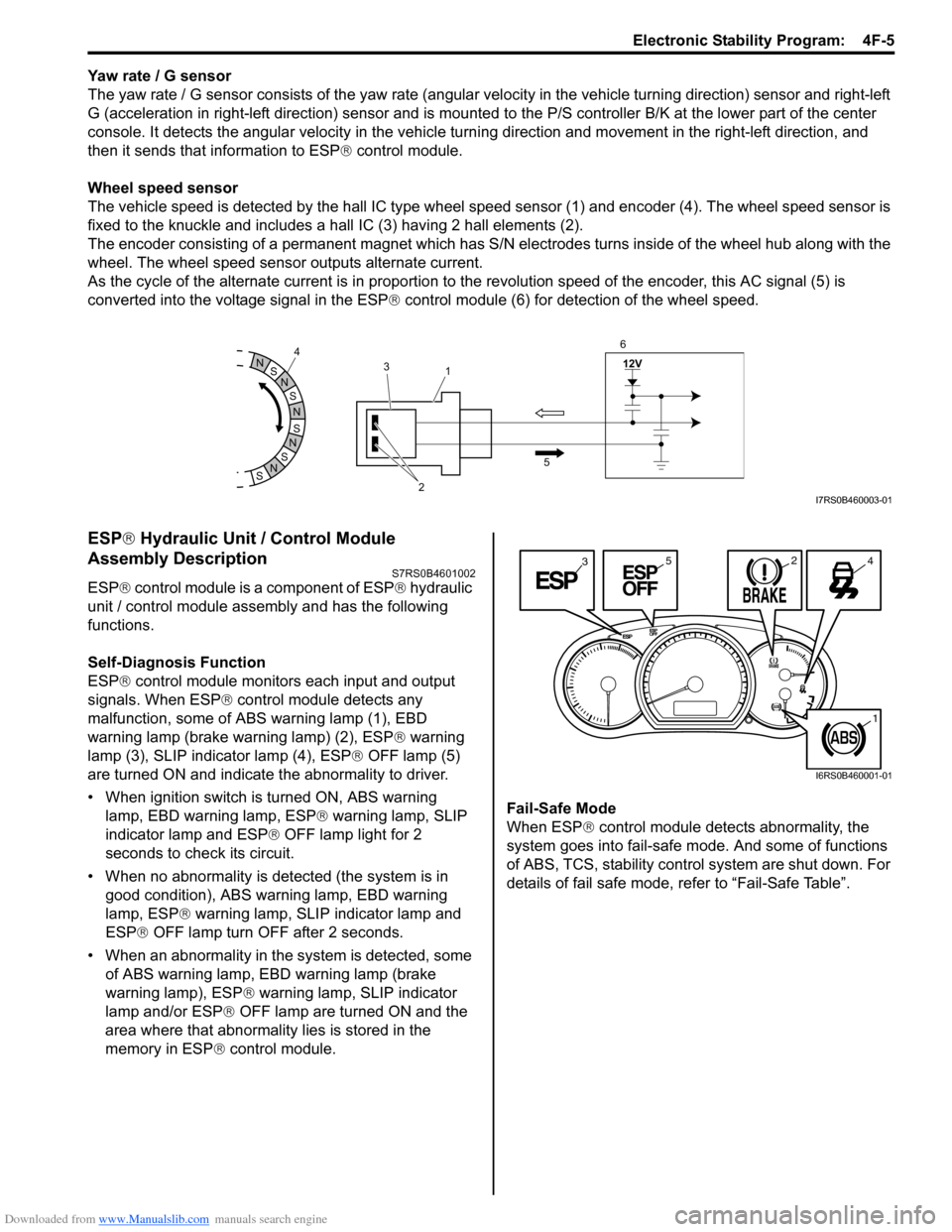
Wheel speed sensor
The vehicle speed is detected by the hall IC type wheel speed sensor (1) and encoder (4). The wheel speed sensor is
fixed to the knuckle and includes a hall IC (3) having 2 hall elements (2).
The encoder consisting of a permanent ma gnet which has S/N electrodes turns inside of the wheel hub along with the
wheel. The wheel speed sensor outputs alternate current.
As the cycle of the alternate current is in proportion to the revolution speed of the encoder, this AC signal (5) is
converted into the voltage signal in the ESP ® control module (6) for detection of the wheel speed.
ESP ® Hydraulic Unit / Control Module
Assembly Description
S7RS0B4601002
ESP ® control module is a component of ESP ® hydraulic
unit / control module assembly and has the following
functions.
Self-Diagnosis Function
ESP ® control module monitors each input and output
signals. When ESP ® control module detects any
malfunction, some of ABS warning lamp (1), EBD
warning lamp (brake warning lamp) (2), ESP ® warning
lamp (3), SLIP indicator lamp (4), ESP ® OFF lamp (5)
are turned ON and indicate the abnormality to driver.
• When ignition switch is turned ON, ABS warning lamp, EBD warning lamp, ESP ® warning lamp, SLIP
indicator lamp and ESP ® OFF lamp light for 2
seconds to check its circuit.
• When no abnormality is detected (the system is in good condition), ABS warning lamp, EBD warning
lamp, ESP ® warning lamp, SLIP indicator lamp and
ESP ® OFF lamp turn OFF after 2 seconds.
• When an abnormality in the system is detected, some of ABS warning lamp, EBD warning lamp (brake
warning lamp), ESP ® warning lamp, SLIP indicator
lamp and/or ESP ® OFF lamp are turned ON and the
area where that abnormality lies is stored in the
memory in ESP ® control module. Fail-Safe Mode
When ESP
® control module detects abnormality, the
system goes into fail-safe mode. And some of functions
of ABS, TCS, stability control system are shut down. For
details of fail safe mode, re fer to “Fail-Safe Table”.
S
N
S
N
S
N
N
S
N
S
12V
2
3
1
5
4
6I7RS0B460003-01
3245
1
I6RS0B460001-01
Page 581 of 1496
Downloaded from www.Manualslib.com manuals search engine Electronic Stability Program: 4F-7
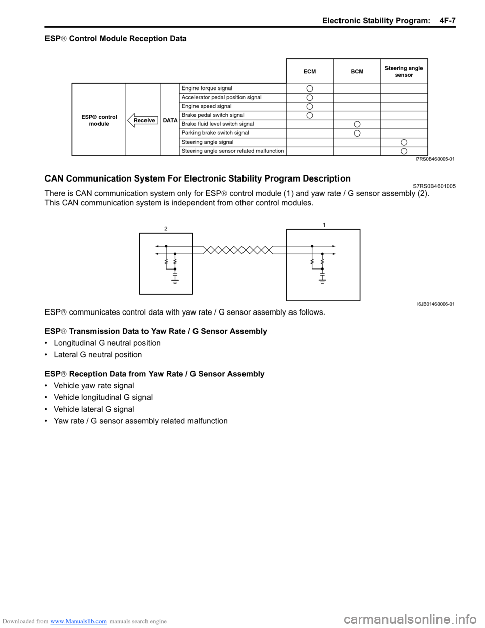
ESP® Control Module Reception Data
CAN Communication System For Electronic Stability Program DescriptionS7RS0B4601005
There is CAN communication system only for ESP ® control module (1) and yaw rate / G sensor assembly (2).
This CAN communication system is independent from other control modules.
ESP ® communicates control data with yaw rate / G sensor assembly as follows.
ESP ® Transmission Data to Yaw Rate / G Sensor Assembly
• Longitudinal G neutral position
• Lateral G neutral position
ESP ® Reception Data from Yaw Rate / G Sensor Assembly
• Vehicle yaw rate signal
• Vehicle longitudinal G signal
• Vehicle lateral G signal
• Yaw rate / G sensor assembly related malfunction
BCM
Receive DATA
ESP® control
moduleECMSteering angle sensor
Engine torque signal
Accelerator pedal position signal
Engine speed signal
Brake pedal switch signal
Brake fluid level switch signal
Parking brake switch signal
Steering angle signal
Steering angle sensor related malfunction
I7RS0B460005-01
2 1
I6JB01460006-01
Page 589 of 1496
Downloaded from www.Manualslib.com manuals search engine Electronic Stability Program: 4F-15
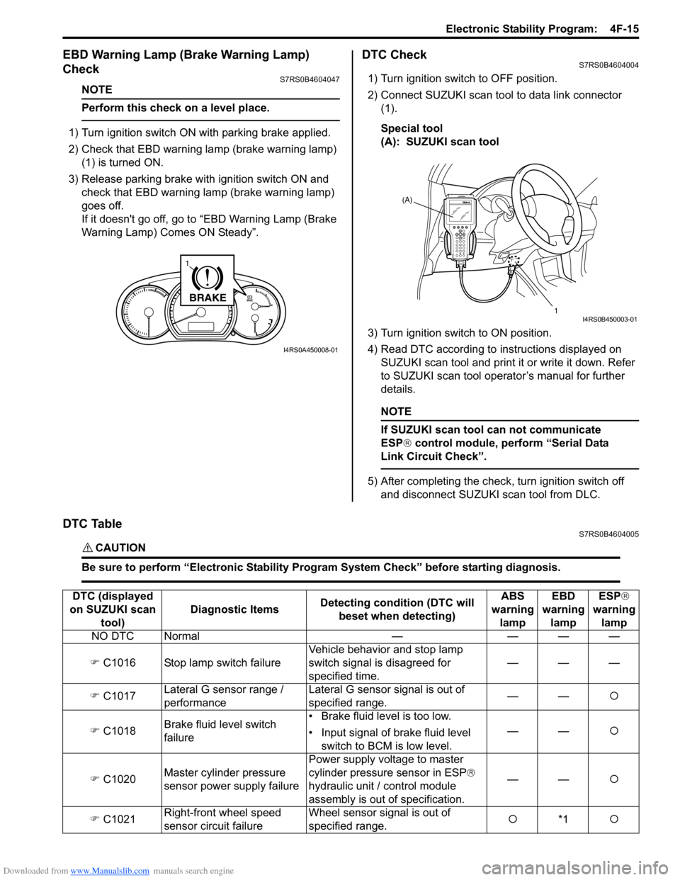
EBD Warning Lamp (Brake Warning Lamp)
Check
S7RS0B4604047
NOTE
Perform this check on a level place.
1) Turn ignition switch ON with parking brake applied.
2) Check that EBD warning lamp (brake warning lamp)
(1) is turned ON.
3) Release parking brake with ignition switch ON and check that EBD warning lamp (brake warning lamp)
goes off.
If it doesn't go off, go to “EBD Warning Lamp (Brake
Warning Lamp) Comes ON Steady”.
DTC CheckS7RS0B4604004
1) Turn ignition switch to OFF position.
2) Connect SUZUKI scan tool to data link connector (1).
Special tool
(A): SUZUKI scan tool
3) Turn ignition switch to ON position.
4) Read DTC according to instructions displayed on
SUZUKI scan tool and print it or write it down. Refer
to SUZUKI scan tool operator’s manual for further
details.
NOTE
If SUZUKI scan tool can not communicate
ESP® control module, perform “Serial Data
Link Circuit Check”.
5) After completing the check, turn ignition switch off and disconnect SUZUKI scan tool from DLC.
DTC TableS7RS0B4604005
CAUTION!
Be sure to perform “Electronic Stability Program System Check” before starting diagnosis.
BRAKE
1
I4RS0A450008-01
(A)
1
I4RS0B450003-01
DTC (displayed
on SUZUKI scan tool) Diagnostic Items
Detecting condition (DTC will
beset when detecting) ABS
warning lamp EBD
warning lamp ESP
®
warning lamp
NO DTC Normal — — — —
�) C1016 Stop lamp switch failure Vehicle behavior and stop lamp
switch signal is disagreed for
specified time.———
�) C1017 Lateral G sensor range /
performance Lateral G sensor signal is out of
specified range.
——
�{
�) C1018 Brake fluid level switch
failure • Brake fluid level is too low.
• Input signal of brake fluid level
switch to BCM is low level. ——
�{
�) C1020 Master cylinder pressure
sensor power supply failure Power supply volt
age to master
cylinder pressure sensor in ESP ®
hydraulic unit / control module
assembly is out of specification. ——
�{
�) C1021 Right-front wheel speed
sensor circuit failure Wheel sensor signal is out of
specified range.
�{
*1 �{
Page 590 of 1496
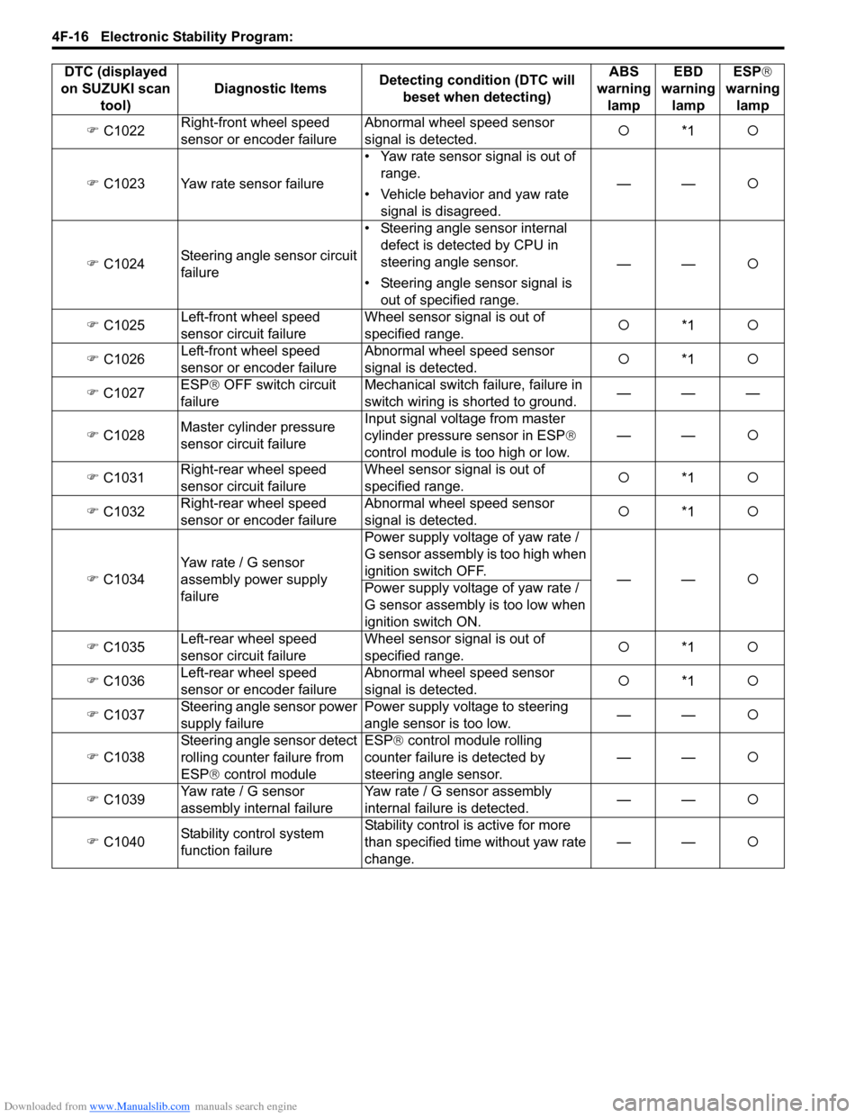
Downloaded from www.Manualslib.com manuals search engine 4F-16 Electronic Stability Program:
�) C1022 Right-front wheel speed
sensor or encoder failure Abnormal wheel speed sensor
signal is detected.
�{
*1 �{
�) C1023 Yaw rate sensor failure • Yaw rate sensor signal is out of
range.
• Vehicle behavior and yaw rate signal is disagreed. ——
�{
�) C1024 Steering angle sensor circuit
failure • Steering angle sensor internal
defect is detected by CPU in
steering angle sensor.
• Steering angle sensor signal is out of specified range. ——
�{
�) C1025 Left-front wheel speed
sensor circuit failure Wheel sensor signal is out of
specified range.
�{
*1 �{
�) C1026 Left-front wheel speed
sensor or encoder failure Abnormal wheel speed sensor
signal is detected.
�{
*1 �{
�) C1027 ESP
® OFF switch circuit
failure Mechanical switch failure, failure in
switch wiring is shorted to ground.
———
�) C1028 Master cylinder pressure
sensor circuit failure Input signal voltage from master
cylinder pressure sensor in ESP
®
control module is too high or low. ——
�{
�) C1031 Right-rear wheel speed
sensor circuit failure Wheel sensor signal is out of
specified range.
�{
*1 �{
�) C1032 Right-rear wheel speed
sensor or encoder failure Abnormal wheel speed sensor
signal is detected.
�{
*1 �{
�) C1034 Yaw rate / G sensor
assembly power supply
failure Power supply voltage of yaw rate /
G sensor assembly is too high when
ignition switch OFF.
——�{
Power supply voltage of yaw rate /
G sensor assembly is too low when
ignition switch ON.
�) C1035 Left-rear wheel speed
sensor circuit failure Wheel sensor signal is out of
specified range.
�{
*1 �{
�) C1036 Lef
t-rear wheel speed
sensor or encoder failure Abnormal wheel speed sensor
signal is detected.
�{
*1 �{
�) C1037 Steering angle sensor power
supply failure Power supply voltage to steering
angle sensor is too low.
——
�{
�) C1038 Steering angle sensor detect
rolling counter failure from
ESP
® control module ESP
® control module rolling
counter failure is detected by
steering angle sensor. ——
�{
�) C1039 Yaw rate / G sensor
assembly internal failure Yaw rate / G sensor assembly
internal failure is detected.
——
�{
�) C1040 Stability control system
function failure Stability control is active for more
than specified time
without yaw rate
change. ——
�{
DTC (displayed
on SUZUKI scan tool) Diagnostic Items
Detecting condition (DTC will
beset when detecting) ABS
warning lamp EBD
warning lamp ESP
®
warning lamp