low pressure SUZUKI SWIFT 2008 2.G Service Repair Manual
[x] Cancel search | Manufacturer: SUZUKI, Model Year: 2008, Model line: SWIFT, Model: SUZUKI SWIFT 2008 2.GPages: 1496, PDF Size: 34.44 MB
Page 227 of 1496
Downloaded from www.Manualslib.com manuals search engine Engine General Information and Diagnosis: 1A-177
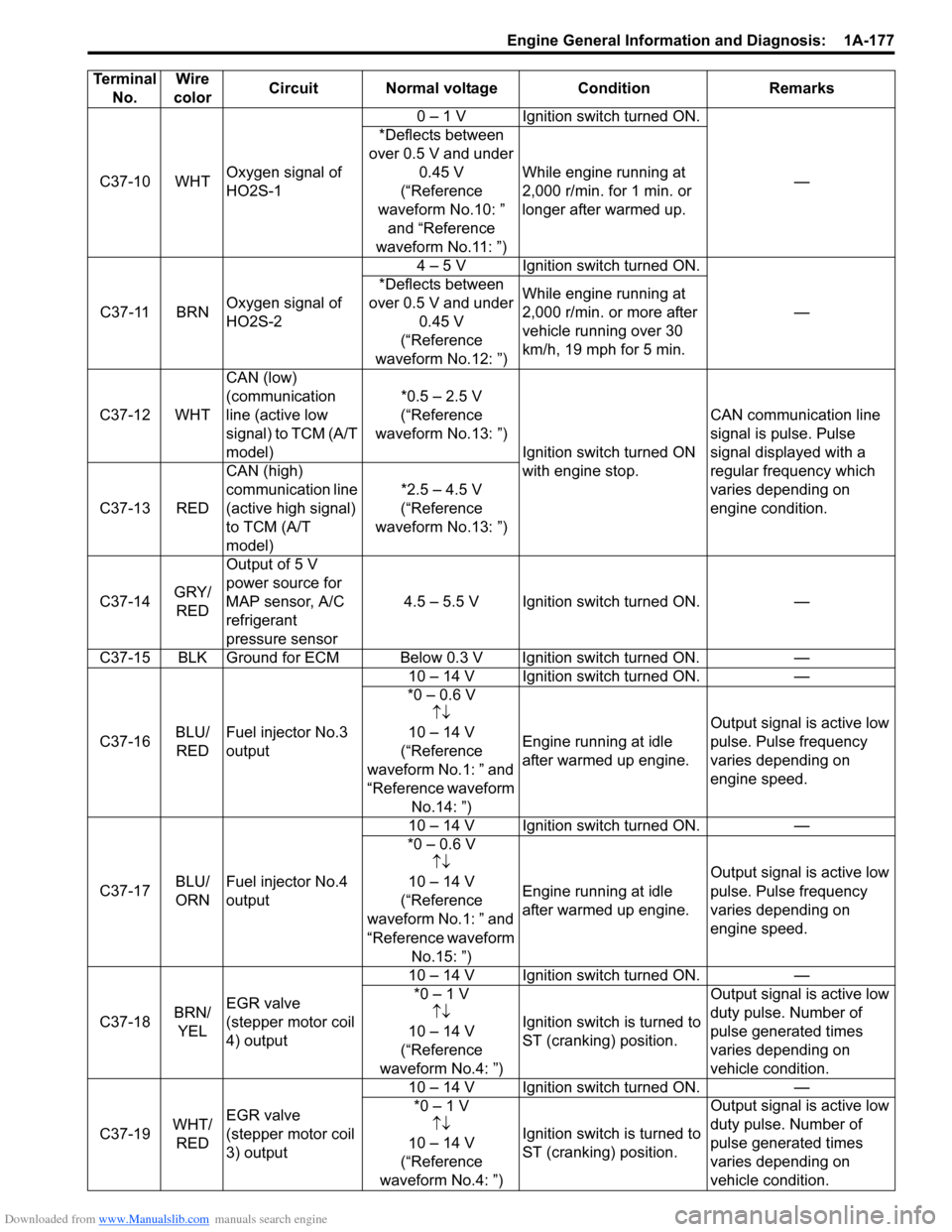
C37-10 WHTOxygen signal of
HO2S-1 0 – 1 V Ignition switch turned ON.
—
*Deflects between
over 0.5 V and under 0.45 V
(“Reference
waveform No.10: ” and “Reference
waveform No.11: ”) While engine running at
2,000 r/min. for 1 min. or
longer after warmed up.
C37-11 BRN Oxygen signal of
HO2S-2 4 – 5 V Ignition switch turned ON.
—
*Deflects between
over 0.5 V and under 0.45 V
(“Reference
waveform No.12: ”) While engine running at
2,000 r/min. or more after
vehicle running over 30
km/h, 19 mph for 5 min.
C37-12 WHT CAN (low)
(communication
line (active low
signal) to TCM (A/T
model) *0.5 – 2.5 V
(“Reference
waveform No.13: ”) Ignition switch turned ON
with engine stop. CAN communication line
signal is pulse. Pulse
signal displayed with a
regular frequency which
varies depending on
engine condition.
C37-13 RED CAN (high)
communication line
(active high signal)
to TCM (A/T
model) *2.5 – 4.5 V
(“Reference
waveform No.13: ”)
C37-14 GRY/
RED Output of 5 V
power source for
MAP sensor, A/C
refrigerant
pressure sensor
4.5 – 5.5 V Ignition switch turned ON. —
C37-15 BLK Ground for ECM Below 0.3 V Ignition switch turned ON. —
C37-16 BLU/
RED Fuel injector No.3
output 10 – 14 V Ignition switch turned ON. —
*0 – 0.6 V ↑↓
10 – 14 V
(“Reference
waveform No.1: ” and
“Reference waveform No.14: ”) Engine running at idle
after warmed up engine.
Output signal is active low
pulse. Pulse frequency
varies depending on
engine speed.
C37-17 BLU/
ORNFuel injector No.4
output 10 – 14 V Ignition switch turned ON. —
*0 – 0.6 V ↑↓
10 – 14 V
(“Reference
waveform No.1: ” and
“Reference waveform No.15: ”) Engine running at idle
after warmed up engine.
Output signal is active low
pulse. Pulse frequency
varies depending on
engine speed.
C37-18 BRN/
YEL EGR valve
(stepper motor coil
4) output 10 – 14 V Ignition switch turned ON. —
*0 – 1 V ↑↓
10 – 14 V
(“Reference
waveform No.4: ”) Ignition switch is turned to
ST (cranking) position. Output signal is active low
duty pulse. Number of
pulse generated times
varies depending on
vehicle condition.
C37-19 WHT/
RED EGR valve
(stepper motor coil
3) output 10 – 14 V Ignition switch turned ON. —
*0 – 1 V ↑↓
1
0 – 14 V
(“Reference
waveform No.4: ”) Ignition switch is turned to
ST (cranking) position. Output signal is active low
duty pulse. Number of
pulse generated times
varies depending on
vehicle condition.
Terminal
No. Wire
color Circuit Normal voltage
ConditionRemarks
Page 230 of 1496
Downloaded from www.Manualslib.com manuals search engine 1A-180 Engine General Information and Diagnosis:
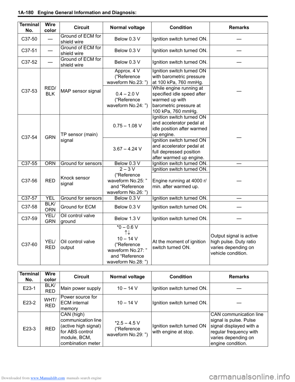
C37-50 —Ground of ECM for
shield wire Below 0.3 V Ignition switch turned ON. —
C37-51 — Ground of ECM for
shield wire Below 0.3 V Ignition switch turned ON. —
C37-52 — Ground of ECM for
shield wire Below 0.3 V Ignition switch turned ON. —
C37-53 RED/
BLK MAP sensor signal Approx. 4 V
(“Reference
waveform No.23: ”) Ignition switch turned ON
with barometric pressure
at 100 kPa, 760 mmHg.
—
0.4 – 2.0 V
(“Reference
waveform No.24: ”) While engine running at
specified idle speed after
warmed up with
barometric pressure at
100 kPa, 760 mmHg.
C37-54 GRN TP sensor (main)
signal 0.75 – 1.08 V
Ignition switch turned ON
and accelerator pedal at
idle position after warmed
up engine.
—
3.67 – 4.24 V Ignition switch turned ON
and accelerator pedal at
full depressed position
after warmed up engine.
C37-55 ORN Ground for sensors Below 0.3 V Ignition switch turned ON. —
C37-56 RED Knock sensor
signal 2 – 3 V
(“Reference
waveform No.25: ” and “Reference
waveform No.26: ”) Ignition switch turned ON.
—
Engine running at 4000 r/
min. after warmed up.
C37-57 YEL Ground for sensors Below 0.3 V Ignition switch turned ON. —
C37-58 BLK/
ORN Ground for ECM Below 0.3 V Ignition switch turned ON.
—
C37-59 YEL/
GRN Oil control valve
ground
Below 1.3 V Ignition switch turned ON.
—
C37-60 YEL/
RED Oil control valve
output *0 – 0.6 V
↑↓
10 – 14 V
(“Reference
waveform No.27: ” and “Reference
waveform No.28: ”) At the moment of ignition
switch turned ON.
Output signal is active
high pulse. Duty ratio
varies depending on
vehicle condition.
Terminal
No. Wire
color Circuit Normal voltage
ConditionRemarks
Terminal
No. Wire
color Circuit Normal voltage Condition Remarks
E23-1 BLK/
RED Main power supply 10 – 14 V Ignition switch turned ON. —
E23-2 WHT/
RED Power source for
ECM internal
memory
10 – 14 V Ignition switch turned ON. —
E23-3 RED CAN (high)
communication line
(active high signal)
for ABS control
module, BCM,
combination meter *2.5 – 4.5 V
(“Reference
waveform No.29: ”) Ignition switch turned ON
with engine at stop. CAN communication line
signal is pulse. Pulse
signal displayed with a
regular frequency with
varies depending on
engine condition.
Page 233 of 1496
Downloaded from www.Manualslib.com manuals search engine Engine General Information and Diagnosis: 1A-183
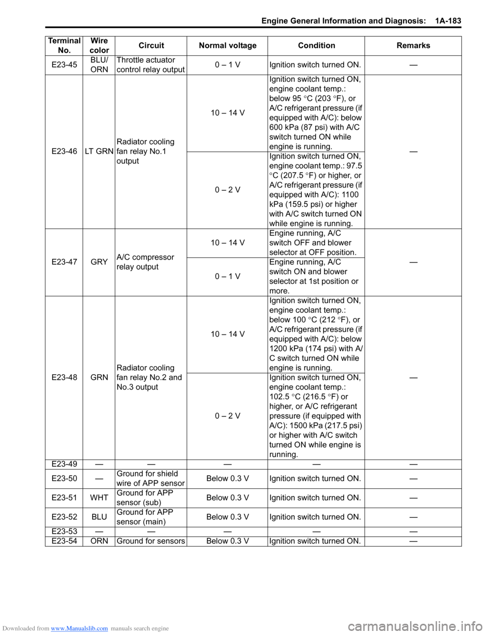
E23-45BLU/
ORNThrottle actuator
control relay output
0 – 1 V Ignition switch turned ON. —
E23-46 LT GRN Radiator cooling
fan relay No.1
output 10 – 14 V
Ignition switch turned ON,
engine coolant temp.:
below 95
°C (203 ° F), or
A/C refrigerant pressure (if
equipped with A/C): below
600 kPa (87 psi) with A/C
switch turned ON while
engine is running. —
0 – 2 V Ignition switch turned ON,
engine coolant temp.: 97.5
°
C (207.5 ° F) or higher, or
A/C refrigerant pressure (if
equipped with A/C): 1100
kPa (159.5 psi) or higher
with A/C switch turned ON
while engine is running.
E23-47 GRY A/C compressor
relay output 10 – 14 V
Engine running, A/C
switch OFF and blower
selector at OFF position.
—
0 – 1 V Engine running, A/C
switch ON and blower
selector at 1st position or
more.
E23-48 GRN Radiator cooling
fan relay No.2 and
No.3 output 10 – 14 V
Ignition switch turned ON,
engine coolant temp.:
below 100
°C (212 °F), or
A/C refrigerant pressure (if
equipped with A/C): below
1200 kPa (174 psi) with A/
C switch turned ON while
engine is running. —
0 – 2 V Ignition switch turned ON,
engine coolant temp.:
102.5
°C (216.5 °F) or
higher, or A/C refrigerant
pressure (if equipped with
A/C): 1500 kPa (217.5 psi)
or higher with A/C switch
turned ON while engine is
running.
E23-49 — — — — —
E23-50 — Ground for shield
wire of APP sensor Below 0.3 V Ignition switch turned ON. —
E23-51 WHT Ground for APP
sensor (sub) Below 0.3 V Ignition switch turned ON. —
E23-52 BLU Ground for APP
sensor (main) Below 0.3 V Ignition switch turned ON. —
E23-53 — — — — —
E23-54 ORN Ground for sensors Below 0.3 V Ignition switch turned ON. —
Terminal
No. Wire
color Circuit Normal voltage Condition Remarks
Page 234 of 1496
Downloaded from www.Manualslib.com manuals search engine 1A-184 Engine General Information and Diagnosis:
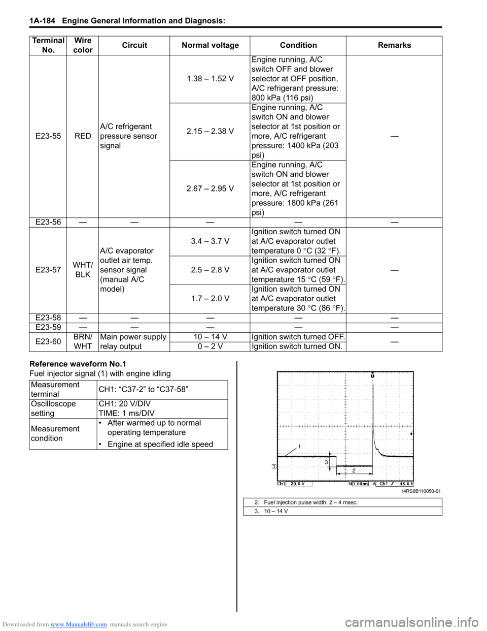
Reference waveform No.1
Fuel injector signal (1) with engine idling
E23-55 RED
A/C refrigerant
pressure sensor
signal 1.38 – 1.52 V
Engine running, A/C
switch OFF and blower
selector at OFF position,
A/C refrigerant pressure:
800 kPa (116 psi)
—
2.15 – 2.38 V Engine running, A/C
switch ON and blower
selector at 1st position or
more, A/C refrigerant
pressure: 1400 kPa (203
psi)
2.67 – 2.95 V Engine running, A/C
switch ON and blower
selector at 1st position or
more, A/C refrigerant
pressure: 1800 kPa (261
psi)
E23-56 — — — — —
E23-57 WHT/
BLK A/C evaporator
outlet air temp.
sensor signal
(manual A/C
model) 3.4 – 3.7 V
Ignition switch turned ON
at A/C evaporator outlet
temperature 0
°C (32 °F).
—
2.5 – 2.8 V Ignition switch turned ON
at A/C evaporator outlet
temperature 15
°C (59 °F).
1.7 – 2.0 V Ignition switch turned ON
at A/C evaporator outlet
temperature 30
°C (86 °F).
E23-58 — — — — —
E23-59 — — — — —
E23-60 BRN/
WHT Main power supply
relay output 10 – 14 V Ignition switch turned OFF.
—
0 – 2 V Ignition switch turned ON.
Terminal
No. Wire
color Circuit Normal voltage Condition Remarks
Measurement
terminal CH1: “C37-2” to “C37-58”
Oscilloscope
setting CH1: 20 V/DIV
TIME: 1 ms/DIV
Measurement
condition • After warmed up to normal
operating temperature
• Engine at specified idle speed
2. Fuel injection pulse width: 2 – 4 msec.
3. 10 – 14 V
I4RS0B110050-01
Page 254 of 1496
Downloaded from www.Manualslib.com manuals search engine 1A-204 Engine General Information and Diagnosis:
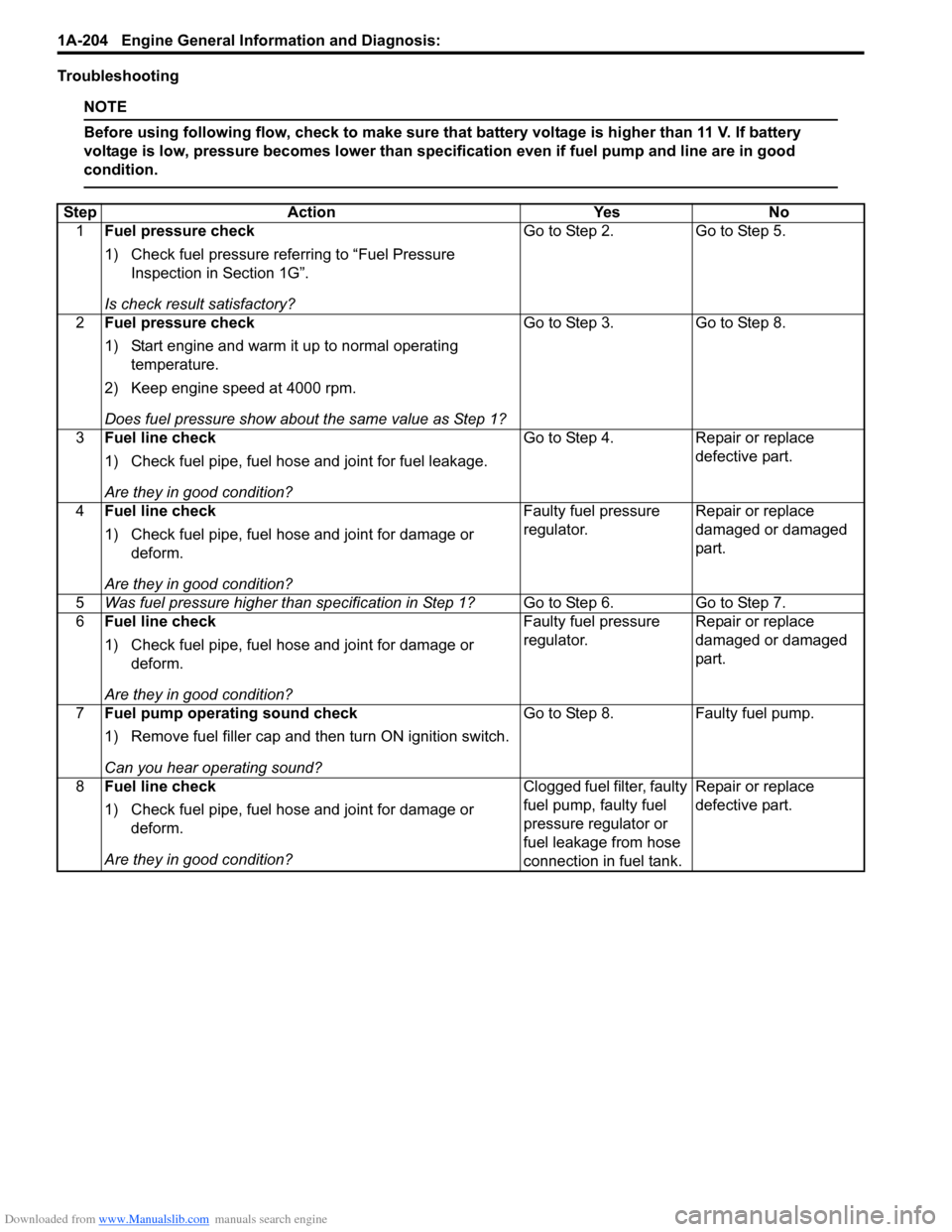
Troubleshooting
NOTE
Before using following flow, check to make sure that battery voltage is higher than 11 V. If battery
voltage is low, pressure becomes lower than specification even if fuel pump and line are in good
condition.
StepAction YesNo
1 Fuel pressure check
1) Check fuel pressure referring to “Fuel Pressure
Inspection in Section 1G”.
Is check result satisfactory? Go to Step 2.
Go to Step 5.
2 Fuel pressure check
1) Start engine and warm it up to normal operating
temperature.
2) Keep engine speed at 4000 rpm.
Does fuel pressure show about the same value as Step 1? Go to Step 3.
Go to Step 8.
3 Fuel line check
1) Check fuel pipe, fuel hose and joint for fuel leakage.
Are they in good condition? Go to Step 4.
Repair or replace
defective part.
4 Fuel line check
1) Check fuel pipe, fuel hose and joint for damage or
deform.
Are they in good condition? Faulty fuel pressure
regulator.
Repair or replace
damaged or damaged
part.
5 Was fuel pressure higher than specification in Step 1? Go to Step 6.Go to Step 7.
6 Fuel line check
1) Check fuel pipe, fuel hose and joint for damage or
deform.
Are they in good condition? Faulty fuel pressure
regulator.
Repair or replace
damaged or damaged
part.
7 Fuel pump operating sound check
1) Remove fuel filler cap and th en turn ON ignition switch.
Can you hear operating sound? Go to Step 8.
Faulty fuel pump.
8 Fuel line check
1) Check fuel pipe, fuel hose and joint for damage or
deform.
Are they in good condition? Clogged fuel filter, faulty
fuel pump, faulty fuel
pressure regulator or
fuel leakage from hose
connection in fuel tank.Repair or replace
defective part.
Page 255 of 1496
Downloaded from www.Manualslib.com manuals search engine Engine General Information and Diagnosis: 1A-205
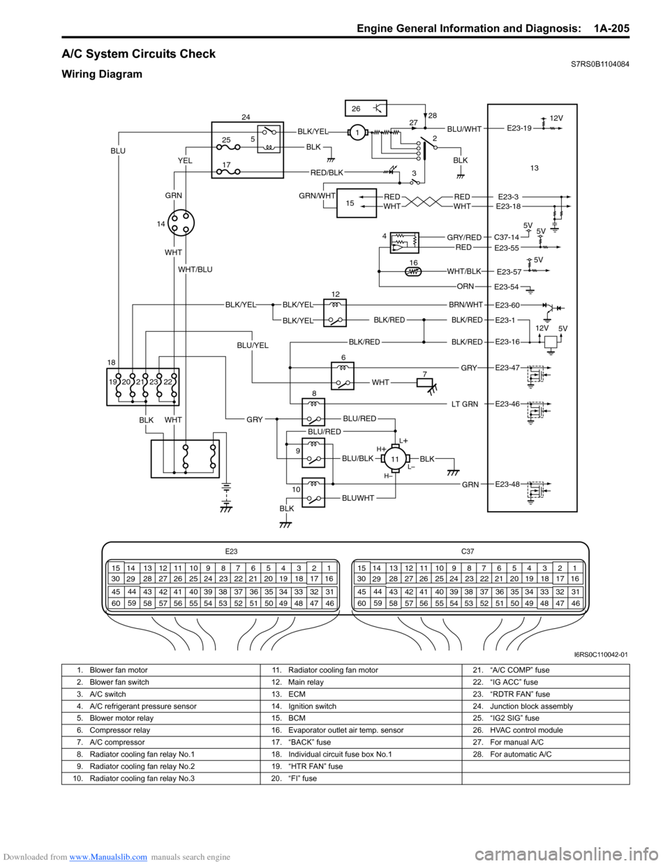
A/C System Circuits CheckS7RS0B1104084
Wiring Diagram
E23C37
34
1819
567
1011
17
20
47 46
495051
2122
52 16
25 9
24
14
29
55
57 54 53
59
60 58 2
262728
15
30
56 4832 31
34353637
40
42 39 38
44
45 43 41 331
1213
238
34
1819
567
1011
17
20
47 46
495051
2122
52 16
25 9
24
14
29
55
57 54 53
59
60 58 2
262728
15
30
56 4832 31
34353637
40
42 39 38
44
45 43 41 331
1213
238
BLK/REDBLK/RED
BLK/YELBLK/YEL
BLK/YEL
BRN/WHT
12V
5V
12
E23-1
E23-60
BLK/RED
LT GRN
BLK/REDE23-16
E23-46
L+
L–
H–
H
+
BLU/RED
BLK
BLUWHTBLK
BLU/BLK
BLU/RED
GRN
GRY
E23-48
8
11
2
3BLU/WHT
REDWHTREDWHTE23-3E23-18
E23-19
6
BLK
WHT
BLK 12V
E23-47 GRY
WHT
YELBLU
WHT
BLK/YEL
RED/BLK
GRN/WHT
WHT/BLU1
713
14
5V
5V
4
E23-55C37-14GRY/REDRED
E23-54ORN 5V
E23-57WHT/BLK16
9
10
25
17
5
24
15
22
BLU/YEL
23212019
GRN
BLK
18
26
28
27
I6RS0C110042-01
1. Blower fan motor 11. Radiator cooling fan motor 21. “A/C COMP” fuse
2. Blower fan switch 12. Main relay 22. “IG ACC” fuse
3. A/C switch 13. ECM 23. “RDTR FAN” fuse
4. A/C refrigerant pressure sensor 14. Ignition switch 24. Junction block assembly
5. Blower motor relay 15. BCM 25. “IG2 SIG” fuse
6. Compressor relay 16. Evaporator outlet air temp. sensor 26. HVAC control module
7. A/C compressor 17. “BACK” fuse 27. For manual A/C
8. Radiator cooling fan relay No.1 18. Individual circuit fuse box No.1 28. For automatic A/C
9. Radiator cooling fan relay No.2 19. “HTR FAN” fuse
10. Radiator cooling fan relay No.3 20. “FI” fuse
Page 257 of 1496
Downloaded from www.Manualslib.com manuals search engine Engine General Information and Diagnosis: 1A-207
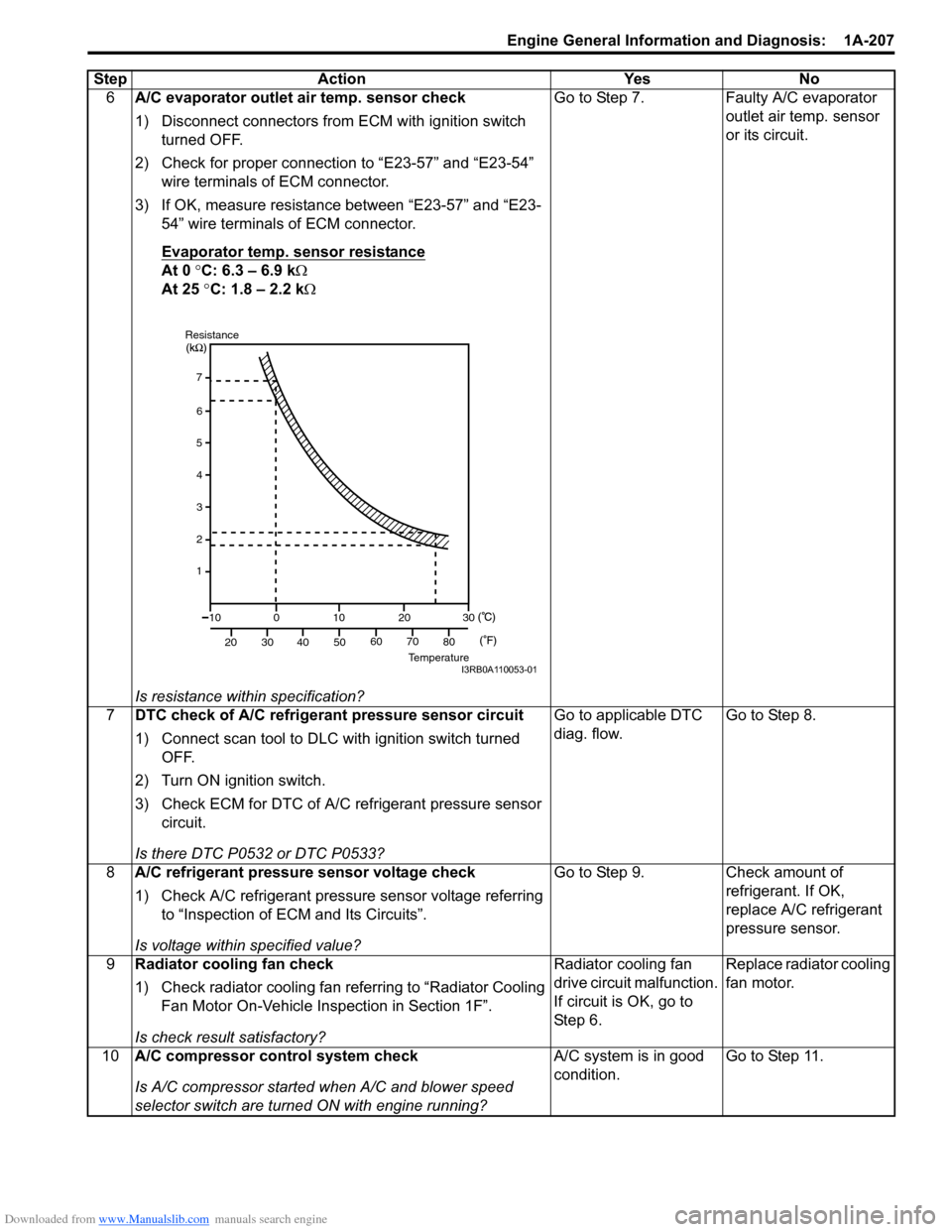
6A/C evaporator outlet air temp. sensor check
1) Disconnect connectors from ECM with ignition switch
turned OFF.
2) Check for proper connection to “E23-57” and “E23-54” wire terminals of ECM connector.
3) If OK, measure resistance between “E23-57” and “E23- 54” wire terminals of ECM connector.
Evaporator temp. sensor resistance
At 0 °C: 6.3 – 6.9 k Ω
At 25 °C: 1.8 – 2.2 k Ω
Is resistance within specification? Go to Step 7. Faulty A/C evaporator
outlet air temp. sensor
or its circuit.
7 DTC check of A/C refrigerant pressure sensor circuit
1) Connect scan tool to DLC with ignition switch turned
OFF.
2) Turn ON ignition switch.
3) Check ECM for DTC of A/C refrigerant pressure sensor circuit.
Is there DTC P0532 or DTC P0533? Go to applicable DTC
diag. flow.
Go to Step 8.
8 A/C refrigerant pressure sensor voltage check
1) Check A/C refrigerant pressure sensor voltage referring
to “Inspection of ECM and Its Circuits”.
Is voltage within specified value? Go to Step 9. Check amount of
refrigerant. If OK,
replace A/C refrigerant
pressure sensor.
9 Radiator cooling fan check
1) Check radiator cooling fan referring to “Radiator Cooling
Fan Motor On-Vehicle Inspection in Section 1F”.
Is check result satisfactory? Radiator cooling fan
drive circuit malfunction.
If circuit is OK, go to
St ep 6 .
Replace radiator cooling
fan motor.
10 A/C compressor control system check
Is A/C compressor started when A/C and blower speed
selector switch are turned ON with engine running? A/C system is in good
condition.
Go to Step 11.
Step Action Yes No
7
6
5
4
3
2
1
10
20 30
40 50
0
10
2030
60 70 80
ResistanceTemperatureI3RB0A110053-01
Page 267 of 1496
Downloaded from www.Manualslib.com manuals search engine Engine General Information and Diagnosis: 1A-217
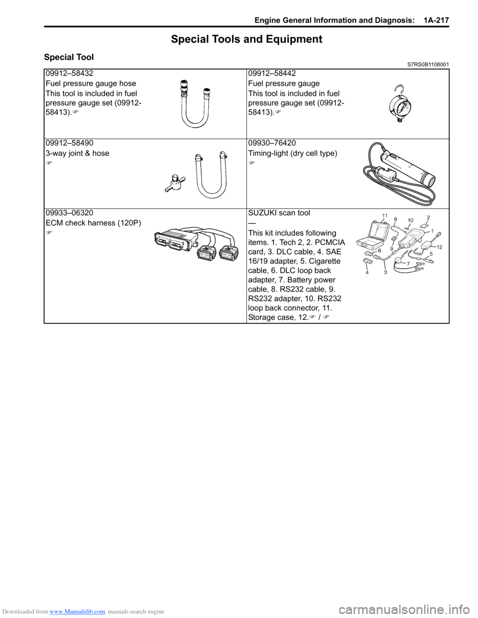
Special Tools and Equipment
Special ToolS7RS0B1108001
09912–5843209912–58442
Fuel pressure gauge hose Fuel pressure gauge
This tool is included in fuel
pressure gauge set (09912-
58413). �) This tool is included in fuel
pressure gauge set (09912-
58413).
�)
09912–58490 09930–76420
3-way joint & hose Timing-light (dry cell type)
�)�)
09933–06320 SUZUKI scan tool
ECM check harness (120P) —
�) This kit includes following
items. 1. Tech 2, 2. PCMCIA
card, 3. DLC cable, 4. SAE
16/19 adapter, 5. Cigarette
cable, 6. DLC loop back
adapter, 7. Battery power
cable, 8. RS232 cable, 9.
RS232 adapter, 10. RS232
loop back connector, 11.
Storage case, 12.�) / �)
Page 278 of 1496
Downloaded from www.Manualslib.com manuals search engine 1C-6 Engine Electrical Devices:
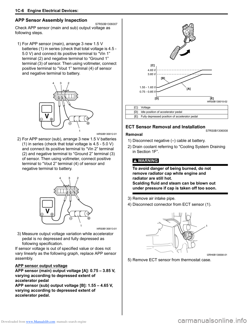
APP Sensor Assembly InspectionS7RS0B1306007
Check APP sensor (main and sub) output voltage as
following steps.
1) For APP sensor (main) , arrange 3 new 1.5 V
batteries (1) in series (check that total voltage is 4.5 -
5.0 V) and connect its positive terminal to “Vin 1”
terminal (2) and negative terminal to “Ground 1”
terminal (3) of sensor. Then using voltmeter, connect
positive terminal to “Vout 1” terminal (4) of sensor
and negative terminal to battery.
2) For APP sensor (s ub), arrange 3 new 1.5 V batteries
(1) in series (check that total voltage is 4.5 - 5.0 V)
and connect its positive terminal to “Vin 2” terminal
(2) and negative terminal to “Ground 2” terminal (3)
of sensor. Then using volt meter, connect positive
terminal to “Vout 2” terminal (4) of sensor and
negative termin al to battery.
3) Measure output voltage variation while accelerator pedal is no depressed and fully depressed as
following specification.
If sensor voltage is out of specified value or does not
vary linearly as the followin g graph, replace APP sensor
assembly.
APP sensor output voltage
APP sensor (main) output voltage [A]: 0.75 – 3.85 V,
varying according to depressed extent of
accelerator pedal
APP sensor (sub) output voltage [B]: 1.55 – 4.65 V,
varying according to depressed extent of
accelerator pedal.
ECT Sensor Removal and InstallationS7RS0B1306008
Removal
1) Disconnect negative (–) cable at battery.
2) Drain coolant referring to “Cooling System Draining in Section 1F”.
WARNING!
To avoid danger of being burned, do not
remove radiator cap while engine and
radiator are still hot.
Scalding fluid and steam can be blown out
under pressure if cap is taken off too soon.
3) Remove air intake pipe.
4) Disconnect connector from ECT sensor (1).
5) Remove ECT sensor from thermostat case.
1
234I4RS0B130012-01
1
234I4RS0B130013-01
[C]: Voltage
[D]: Idle position of accelerator pedal
[E]: Fully depressed position of accelerator pedal
[C]
[B]
[D] [E] [A]
4.65 V
3.85 V
1.55 - 1.65 V
0.75 - 0.85 V
I4RS0B130010-02
1
I2RH0B130008-01
Page 287 of 1496
Downloaded from www.Manualslib.com manuals search engine Engine Mechanical: 1D-2
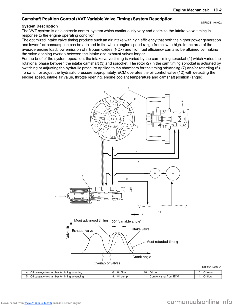
Camshaft Position Control (VVT Variable Valve Timing) System DescriptionS7RS0B1401002
System Description
The VVT system is an electronic control system which continuously vary and optimize the intake valve timing in
response to the engine operating condition.
The optimized intake valve timing produce such an air intake with high efficiency that both the higher power generation
and lower fuel consumption can be attained in the whole engine speed range from low to high. In the area of the
average engine load, low emission of nitrogen oxides (NOx) and high fuel efficiency can also be attained by making
the valve opening overlap between the intake and exhaust valves longer.
For the brief of the system operation, the intake valve timing is varied by the cam timing sprocket (1) which varies the
rotational phase between the intake camshaft (3) and sprocket . The rotor (2) in the cam timing sprocket is actuated by
switching or adjusting the hydraulic pressure applied to the chambers for the timing advancing (7) and/or retarding (6).
To switch or adjust the hydraulic pressure appropriately, ECM operates the oil control valve (12) with detecting the
engine speed, intake air value, throttle opening, engine coolant temperature and camshaft position (angle).
1
4
5
13
10
89
2
7
6
12
11
3
14
60� (variable angle)
Most retarded timing
Most advanced timing
Exhaust valve Intake valve
Crank angle
Overlap of valves
Valve lift
I3RH0B140002-01
4. Oil passage to chamber for timing retarding 8. Oil filter10. Oil pan 13. Oil return
5. Oil passage to chamber for timing advancing 9. Oil pump11. Control signal from ECM 14. Oil flow