HVAC SUZUKI SWIFT 2008 2.G Service Manual PDF
[x] Cancel search | Manufacturer: SUZUKI, Model Year: 2008, Model line: SWIFT, Model: SUZUKI SWIFT 2008 2.GPages: 1496, PDF Size: 34.44 MB
Page 1017 of 1496
Downloaded from www.Manualslib.com manuals search engine Air Conditioning System: Automatic Type 7B-69
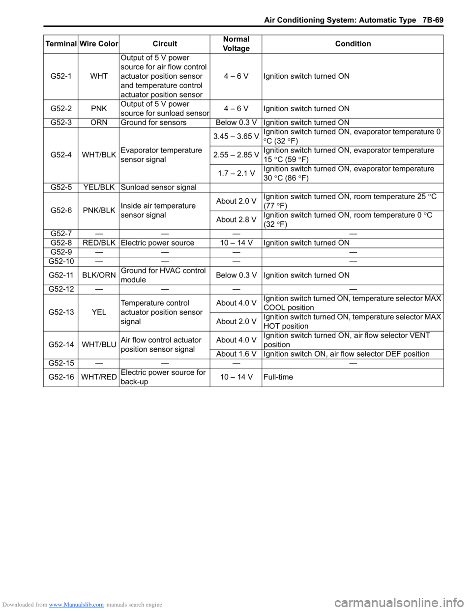
Terminal Wire Color CircuitNormal
Vo l ta g e Condition
G52-1 WHT Output of 5 V power
source for air flow control
actuator position sensor
and temperature control
actuator position sensor 4 – 6 V Ignition switch turned ON
G52-2 PNK Output of 5 V power
source for sunload sensor 4 – 6 V Ignition switch turned ON
G52-3 ORN Ground for sensors Below 0.3 V Ignition switch turned ON
G52-4 WHT/BLK Evaporator temperature
sensor signal 3.45 – 3.65 V
Ignition switch turned ON, evaporator temperature 0
°
C (32 °F)
2.55 – 2.85 V Ignition switch turned ON, evaporator temperature
15
°C (59 ° F)
1.7 – 2.1 V Ignition switch turned ON, evaporator temperature
30
°C (86 ° F)
G52-5 YEL/BLK Sunload sensor signal
G52-6 PNK/BLK Inside air temperature
sensor signal About 2.0 V
Ignition switch turned ON, room temperature 25
°C
(77 °F)
About 2.8 V Ignition switch turned ON, room temperature 0
°C
(32 °F)
G52-7 — — — —
G52-8 RED/BLK Electric power source 10 – 14 V Ignition switch turned ON
G52-9 — — — —
G52-10 — — — —
G52-11 BLK/ORN Ground for HVAC control
module Below 0.3 V Ignition
switch turned ON
G52-12 — — — —
G52-13 YEL Temperature control
actuator position sensor
signal About 4.0 V
Ignition switch turned ON, temperature selector MAX
COOL position
About 2.0 V Ignition switch turned ON, temperature selector MAX
HOT position
G52-14 WHT/BLU Air flow control actuator
position sensor signal About 4.0 V
Ignition switch turned ON
, air flow selector VENT
position
About 1.6 V Ignition switch ON, air flow selector DEF position
G52-15 — — — —
G52-16 WHT/RED Electric power source for
back-up 10 – 14 V Full-time
Page 1020 of 1496
Downloaded from www.Manualslib.com manuals search engine 7B-72 Air Conditioning System: Automatic Type
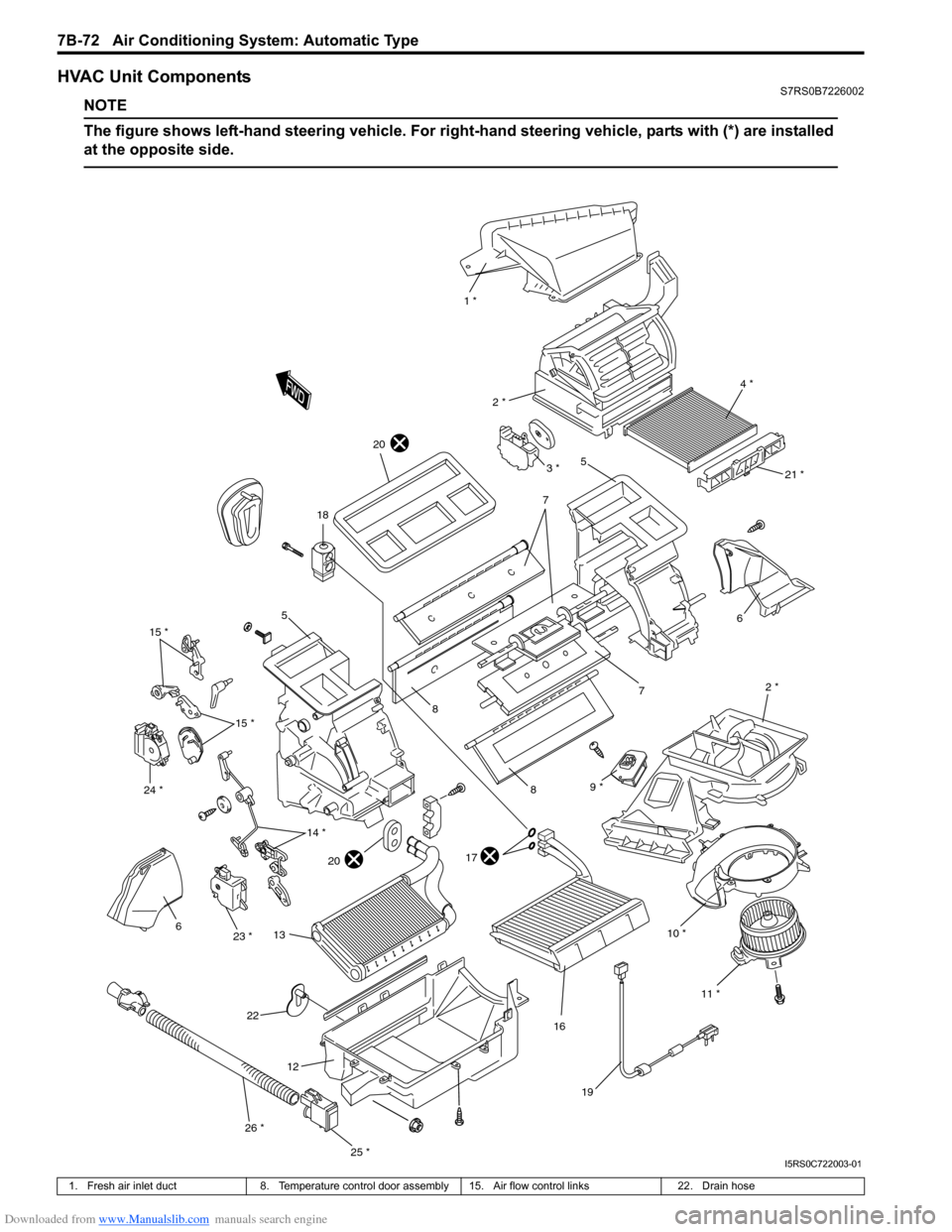
HVAC Unit ComponentsS7RS0B7226002
NOTE
The figure shows left-hand steering vehicle. For right-hand steering vehicle, parts with (*) are installed
at the opposite side.
10 * 2 *
6
7
1 *
4 *
2 *
5
7
8
8
17
16
18
19
6
12
11 *
21 *
20
20
22
9 *
13
3 *
5
15 *
14 *
15 *
23 *
24 *
25 *
26 *
I5RS0C722003-01
1. Fresh air inlet duct
8. Temperature control door assembly 15. Air flow control links 22. Drain hose
Page 1021 of 1496
Downloaded from www.Manualslib.com manuals search engine Air Conditioning System: Automatic Type 7B-73
HVAC Unit Removal and InstallationS7RS0B7226003
Refer to “HVAC Unit Removal and Installation”.
Temperature Control Actuator Removal and
Installation
S7RS0B7226004
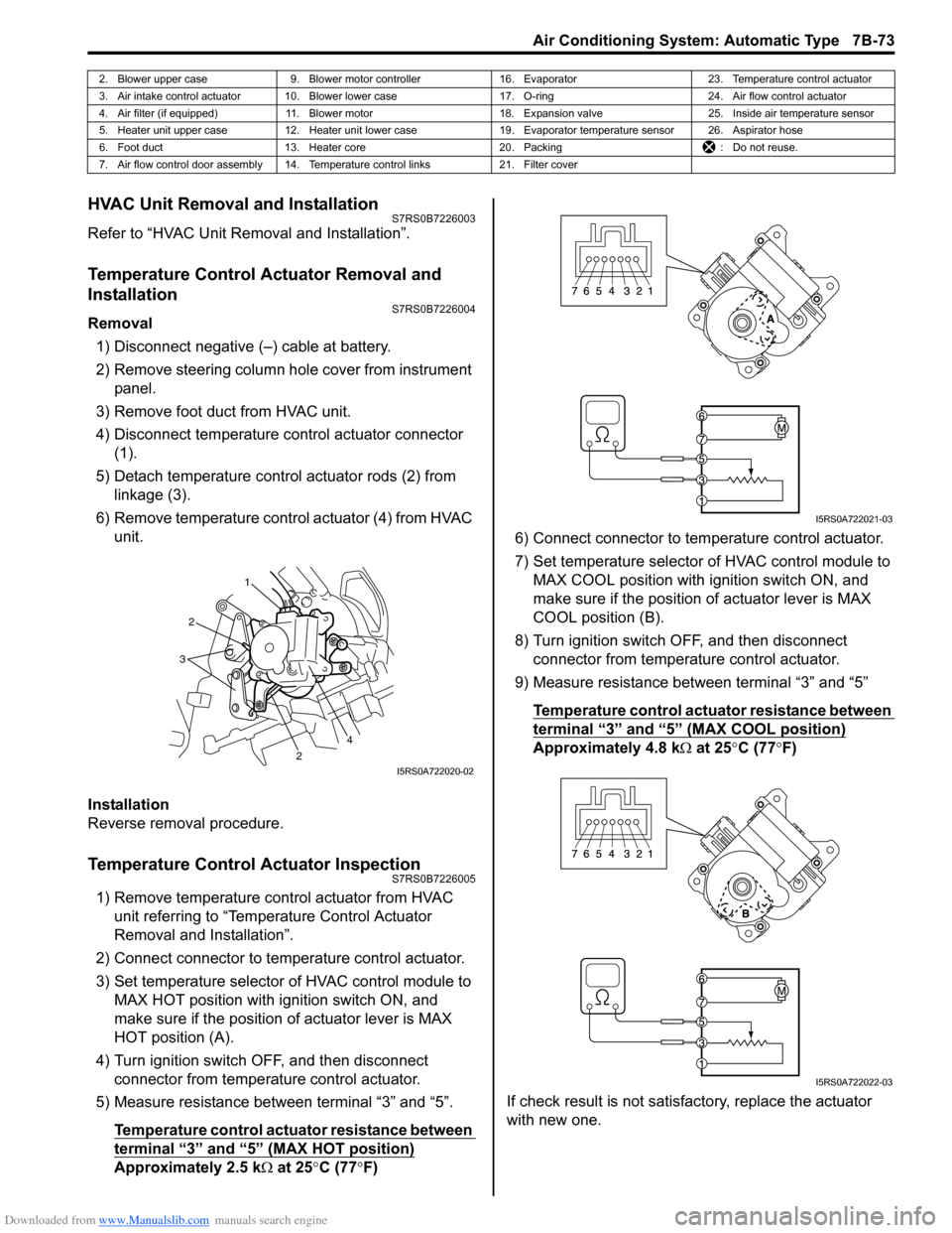
Removal1) Disconnect negative (–) cable at battery.
2) Remove steering column hol e cover from instrument
panel.
3) Remove foot duct from HVAC unit.
4) Disconnect temperature control actuator connector (1).
5) Detach temperature control actuator rods (2) from linkage (3).
6) Remove temperature control actuator (4) from HVAC unit.
Installation
Reverse removal procedure.
Temperature Control Actuator InspectionS7RS0B7226005
1) Remove temperature control actuator from HVAC unit referring to “Temperature Control Actuator
Removal and Installation”.
2) Connect connector to temperature control actuator.
3) Set temperature selector of HVAC control module to MAX HOT position with ignition switch ON, and
make sure if the position of actuator lever is MAX
HOT position (A).
4) Turn ignition switch OFF, and then disconnect connector from temperature control actuator.
5) Measure resistance between terminal “3” and “5”.
Temperature control actuator resistance between
terminal “3” and “5” (MAX HOT position)
Approximately 2.5 k Ω at 25 °C (77 °F) 6) Connect connector to tem
perature control actuator.
7) Set temperature selector of HVAC control module to MAX COOL position with ignition switch ON, and
make sure if the position of actuator lever is MAX
COOL position (B).
8) Turn ignition switch OFF, and then disconnect connector from temperature control actuator.
9) Measure resistance between terminal “3” and “5”
Temperature control actuator resistance between
terminal “3” and “5” (MAX COOL position)
Approximately 4.8 k Ω at 25 °C (77 °F)
If check result is not satisfactory, replace the actuator
with new one.
2. Blower upper case 9. Blower motor controller 16. Evaporator 23. Temperature control actuator
3. Air intake control actuator 10. Blower lower case 17. O-ring24. Air flow control actuator
4. Air filter (if equipped) 11. Blower motor 18. Expansion valve25. Inside air temperature sensor
5. Heater unit upper case 12. Heater unit lower case 19. Evaporator temperature sensor 26. Aspirator hose
6. Foot duct 13. Heater core 20. Packing : Do not reuse.
7. Air flow control door assembly 14. Temperature control links 21. Filter cover
1
2
2
3
4
I5RS0A722020-02
I5RS0A722021-03
I5RS0A722022-03
Page 1022 of 1496
Downloaded from www.Manualslib.com manuals search engine 7B-74 Air Conditioning System: Automatic Type
Air Flow Control Actuator Removal and
Installation
S7RS0B7226006
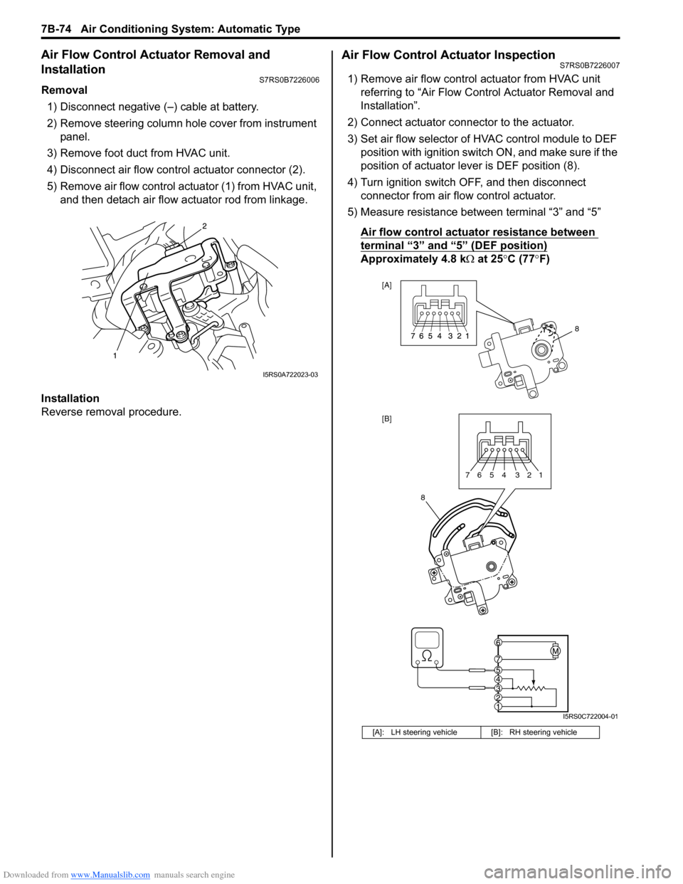
Removal1) Disconnect negative (–) cable at battery.
2) Remove steering column hol e cover from instrument
panel.
3) Remove foot duct from HVAC unit.
4) Disconnect air flow contro l actuator connector (2).
5) Remove air flow control actuator (1) from HVAC unit, and then detach air flow actuator rod from linkage.
Installation
Reverse removal procedure.
Air Flow Control Actuator InspectionS7RS0B7226007
1) Remove air flow control actuator from HVAC unit referring to “Air Flow C ontrol Actuator Removal and
Installation”.
2) Connect actuator connector to the actuator.
3) Set air flow selector of HVAC control module to DEF position with ignition switch ON, and make sure if the
position of actuator lever is DEF position (8).
4) Turn ignition switch OFF, and then disconnect connector from air flow control actuator.
5) Measure resistance between terminal “3” and “5”
Air flow control actuator resistance between
terminal “3” and “5” (DEF position)
Approximately 4.8 k Ω at 25 °C (77 °F)
I5RS0A722023-03
[A]: LH steering vehicle [B]: RH steering vehicle
8
[A]
[B]
8
7654 321
I5RS0C722004-01
Page 1023 of 1496
Downloaded from www.Manualslib.com manuals search engine Air Conditioning System: Automatic Type 7B-75
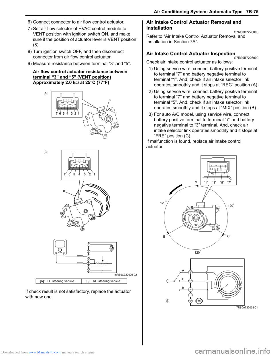
6) Connect connector to air flow control actuator.
7) Set air flow selector of HVAC control module to VENT position with ignition switch ON, and make
sure if the position of act uator lever is VENT position
(8).
8) Turn ignition switch OFF, and then disconnect connector from air flow control actuator.
9) Measure resistance between terminal “3” and “5”.
Air flow control actuator resistance between
terminal “3” and “5” (VENT position)
Approximately 2.0 k Ω at 25 °C (77 °F)
If check result is not satisfactory, replace the actuator
with new one.
Air Intake Control Actuator Removal and
Installation
S7RS0B7226008
Refer to “Air Intake Control Actuator Removal and
Installation in Section 7A”.
Air Intake Control Actuator InspectionS7RS0B7226009
Check air intake contro l actuator as follows:
1) Using service wire, connect battery positive terminal
to terminal “7” and battery negative terminal to
terminal “1”. And, check if air intake selector link
operates smoothly and it stops at “REC” position (A).
2) Using service wire, connect battery positive terminal
to terminal “7” and battery negative terminal to
terminal “5”. And, check if air intake selector link
operates smoothly and it stops at “MIX” position (B).
3) For auto A/C model, using service wire, connect battery positive terminal to terminal “7” and battery
negative terminal to “3” terminal. And, check air
intake selector link operates smoothly and it stops at
“FRE” position (C).
If malfunction is found, replace air intake control
actuator.
[A]: LH steering vehicl e [B]: RH steering vehicle
[A]
[B]
8
8765 4 3 21
I5RS0C722005-02
A
C
B“a”
“a”“a”
-
+
A
C
B “1” “3” “5” “7”
“1”
“3”
“5”
“7”
120
°
120° 120
°
I7RS0A722002-01
Page 1025 of 1496
Downloaded from www.Manualslib.com manuals search engine Air Conditioning System: Automatic Type 7B-77
HVAC Control Module Removal and InstallationS7RS0B7226013
Removal1) Disconnect negative (–) cable at battery.
2) Disable air bag system referring to “Disabling Air Bag System in Section 8B”.
3) Remove passenger air bag module from instrument panel referring to “Passenger Air Bag (Inflator)
Module Removal and Installation in Section 8B”.
4) Remove radio assembly from instrument panel referring to “Rear Speaker Removal and Installation
in Section 9C”.
5) Remove two connectors fr om HVAC control module.
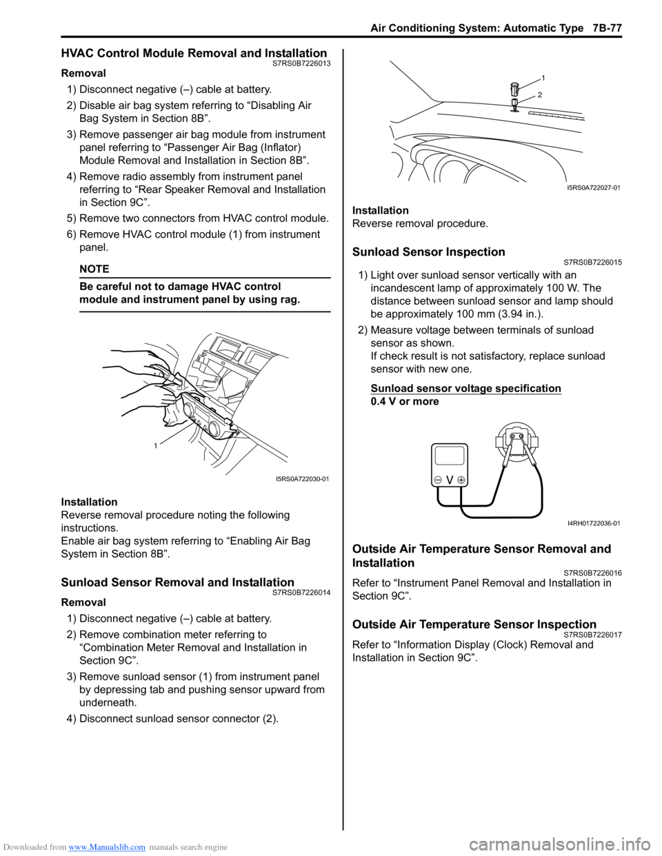
6) Remove HVAC control modu le (1) from instrument
panel.
NOTE
Be careful not to damage HVAC control
module and instrument panel by using rag.
Installation
Reverse removal procedure noting the following
instructions.
Enable air bag system referring to “Enabling Air Bag
System in Section 8B”.
Sunload Sensor Removal and InstallationS7RS0B7226014
Removal
1) Disconnect negative (–) cable at battery.
2) Remove combination meter referring to “Combination Meter Removal and Installation in
Section 9C”.
3) Remove sunload sensor (1) from instrument panel by depressing tab and pushing sensor upward from
underneath.
4) Disconnect sunload sensor connector (2). Installation
Reverse removal procedure.
Sunload Sensor InspectionS7RS0B7226015
1) Light over sunload sensor vertically with an
incandescent lamp of approximately 100 W. The
distance between sunload sensor and lamp should
be approximately 100 mm (3.94 in.).
2) Measure voltage between terminals of sunload sensor as shown.
If check result is not satisfactory, replace sunload
sensor with new one.
Sunload sensor voltage specification
0.4 V or more
Outside Air Temperature Sensor Removal and
Installation
S7RS0B7226016
Refer to “Instrument Panel Re moval and Installation in
Section 9C”.
Outside Air Temperature Sensor InspectionS7RS0B7226017
Refer to “Information Display (Clock) Removal and
Installation in Section 9C”.
1
I5RS0A722030-01
1
2
I5RS0A722027-01
I4RH01722036-01
Page 1189 of 1496
Downloaded from www.Manualslib.com manuals search engine Wiring Systems: 9A-18
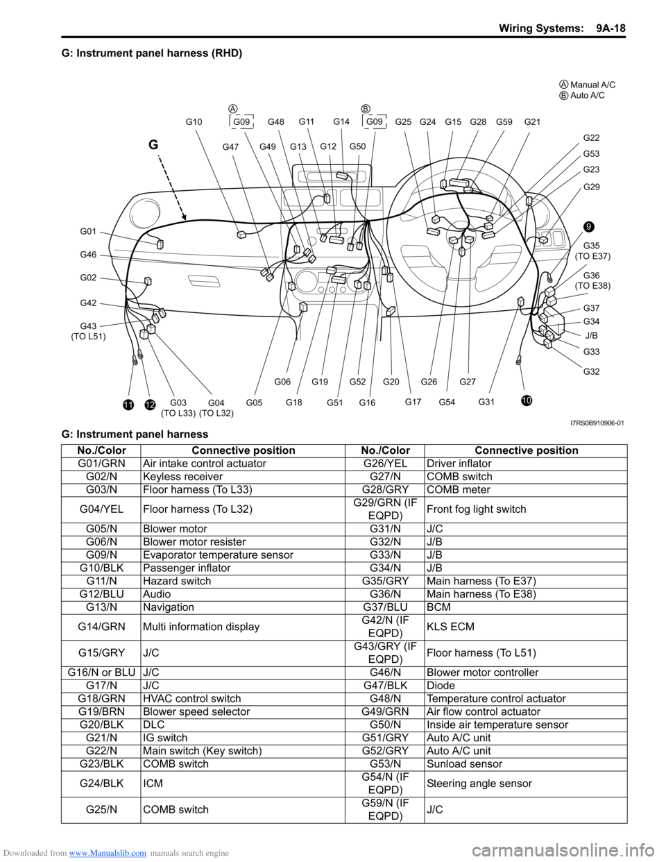
G: Instrument panel harness (RHD)
G: Instrument panel harness
J/B
9
10
G33
G32 G34 G35
(TO E37)
G36
(TO E38)
G31 G29
G23
G53
G22
G21
G28G59
G20G52G27
G54
G261112G03
(TO L33)G04
(TO L32)
G46
G01
G02
G42
G43
(TO L51) G10
G47
G11
G13G49
G14
G09G25 G24G15
G12G50
G48
G17
G16G51
G19
G18
G06
G05
G
G09
G37
A
BManual A/C
Auto A/C
AB
I7RS0B910906-01
No./Color Connective position No./ColorConnective position
G01/GRN Air intake control ac tuatorG26/YEL Driver inflator
G02/N Keyless receiver G27/N COMB switch
G03/N Floor harness (To L33) G28/GRY COMB meter
G04/YEL Floor harness (To L32) G29/GRN (IF
EQPD) Front fog light switch
G05/N Blower motor G31/N J/C
G06/N Blower motor resister G32/N J/B
G09/N Evaporator temperature sensor G33/N J/B
G10/BLK Passenger inflator G34/N J/B
G11/N Hazard switch G35/GRY Main harness (To E37)
G12/BLU Audio G36/N Main harness (To E38)
G13/N Navigation G37/BLU BCM
G14/GRN Multi information display G42/N (IF
EQPD) KLS ECM
G15/GRY J/C G43/GRY (IF
EQPD) Floor harness (To L51)
G16/N or BLU J/C G46/N Blower motor controller
G17/N J/C G47/BLK Diode
G18/GRN HVAC control switch G48/N Temperature control actuator
G19/BRN Blower speed selector G49/GRN Air flow control actuator
G20/BLK DLC G50/N Inside air temperature sensor
G21/N IG switch G51/GRY Auto A/C unit
G22/N Main switch (Key switch) G52/GRY Auto A/C unit
G23/BLK COMB switch G53/N Sunload sensor
G24/BLK ICM G54/N (IF
EQPD) Steering angle sensor
G25/N COMB switch G59/N (IF
EQPD) J/C
Page 1190 of 1496
Downloaded from www.Manualslib.com manuals search engine 9A-19 Wiring Systems:
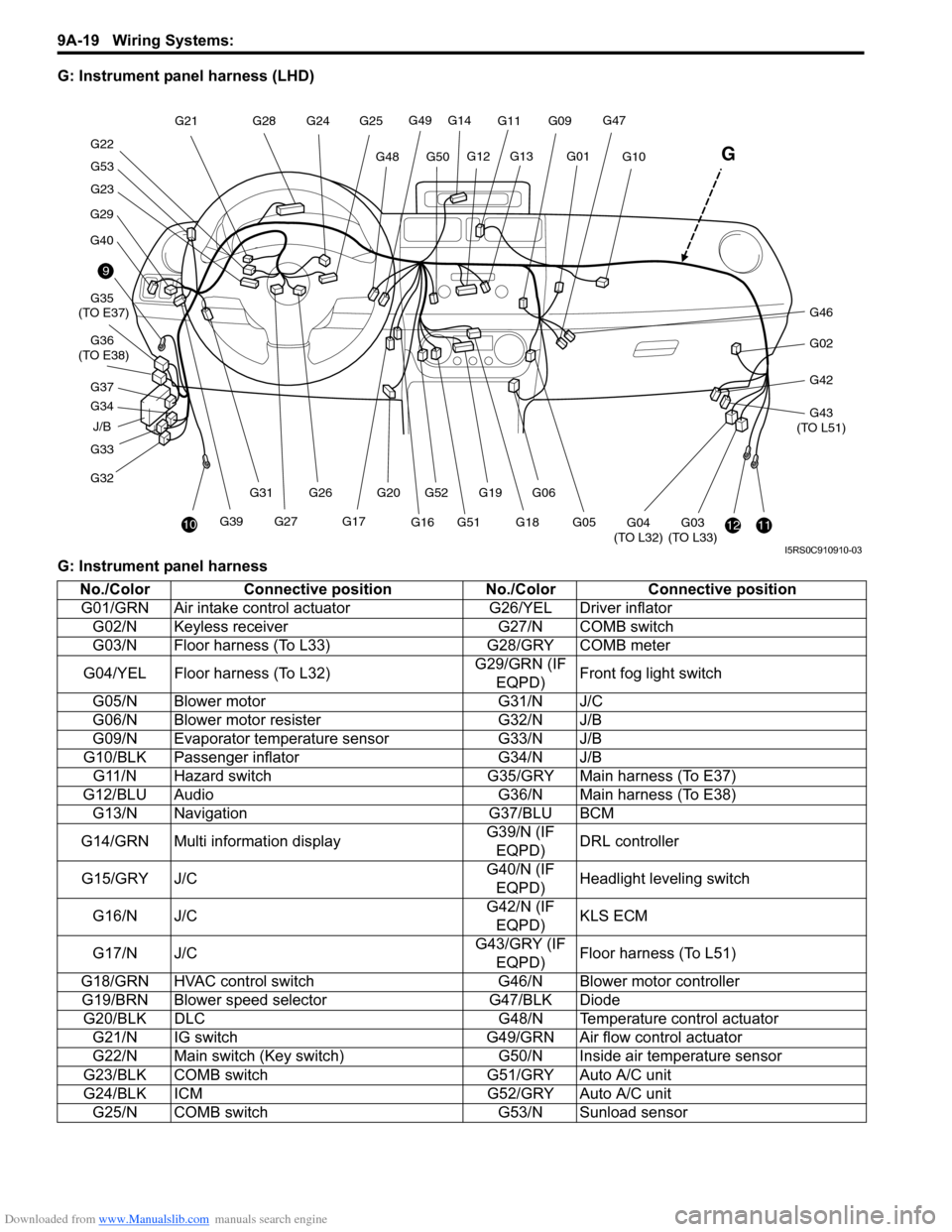
G: Instrument panel harness (LHD)
G: Instrument panel harness
J/B
9
10
G33
G32 G34 G35
(TO E37)
G36
(TO E38)
G29
G40
G23
G53
G22 G21
G28
G20G52
G27G39 G26
G31
1112G03
(TO L33)G04
(TO L32)
G46
G02
G42
G43
(TO L51)
G10
G47G11
G13G01
G14
G49
G50G48
G25
G24
G12
G17
G16G51G19
G18
G06
G05
G
G09
G37
I5RS0C910910-03
No./Color Connective position No./ColorConnective position
G01/GRN Air intake control ac tuatorG26/YEL Driver inflator
G02/N Keyless receiver G27/N COMB switch
G03/N Floor harness (To L33) G28/GRY COMB meter
G04/YEL Floor harness (To L32) G29/GRN (IF
EQPD) Front fog light switch
G05/N Blower motor G31/N J/C
G06/N Blower motor resister G32/N J/B
G09/N Evaporator temperature sensor G33/N J/B
G10/BLK Passenger inflator G34/N J/B
G11/N Hazard switch G35/GRY Main harness (To E37)
G12/BLU Audio G36/N Main harness (To E38)
G13/N Navigation G37/BLU BCM
G14/GRN Multi information display G39/N (IF
EQPD) DRL controller
G15/GRY J/C G40/N (IF
EQPD) Headlight leveling switch
G16/N J/C G42/N (IF
EQPD) KLS ECM
G17/N J/C G43/GRY (IF
EQPD) Floor harness (To L51)
G18/GRN HVAC control switch G46/N Blower motor controller
G19/BRN Blower speed selector G47/BLK Diode
G20/BLK DLC G48/N Temperature control actuator
G21/N IG switch G49/GRN Air flow control actuator
G22/N Main switch (Key switch) G50/N Inside air temperature sensor
G23/BLK COMB switch G51/GRY Auto A/C unit
G24/BLK ICM G52/GRY Auto A/C unit
G25/N COMB switch G53/N Sunload sensor
Page 1206 of 1496
Downloaded from www.Manualslib.com manuals search engine 9A-35 Wiring Systems:
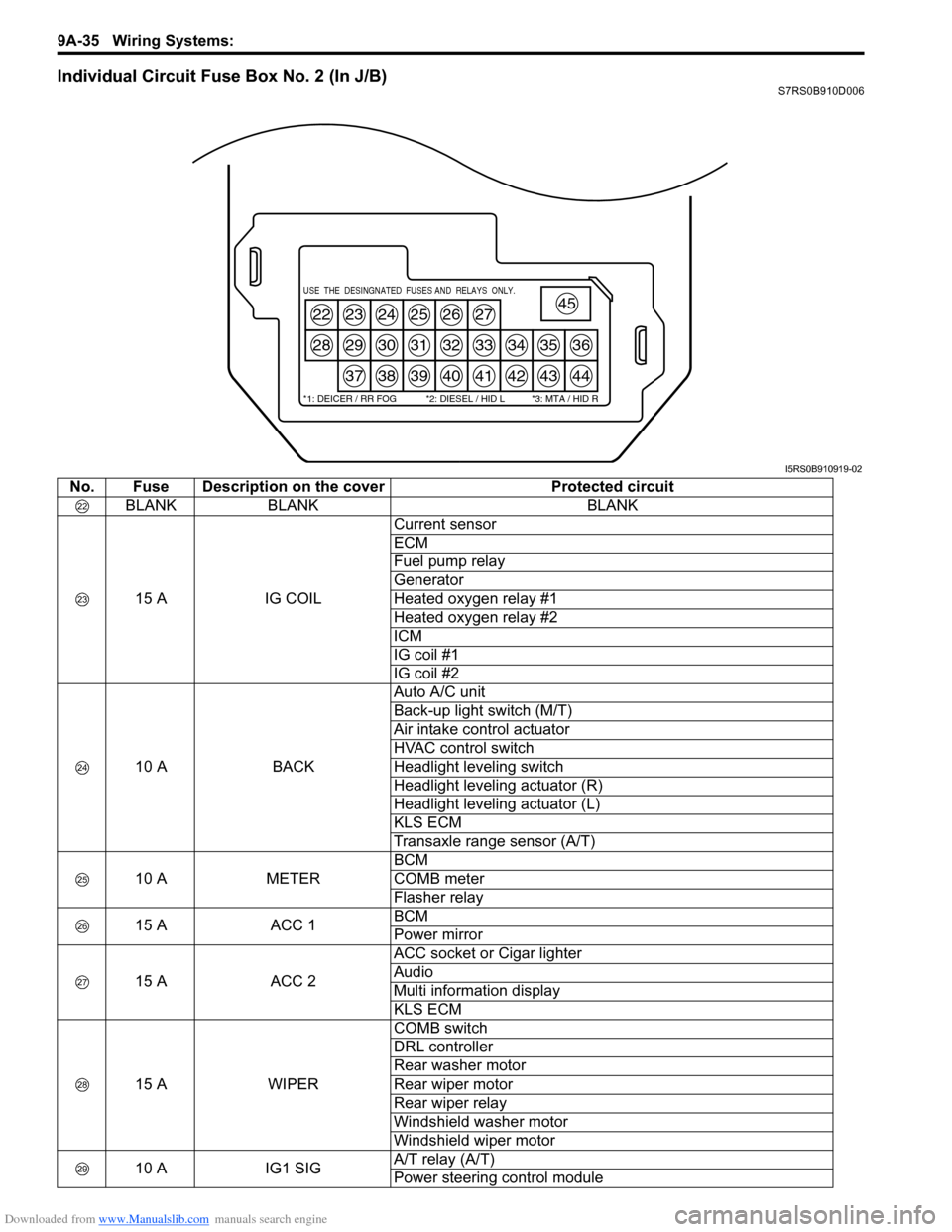
Individual Circuit Fuse Box No. 2 (In J/B)S7RS0B910D006
22
28
23
29
37
24
30
38
25
31
39
26
32
40
27
33
41
34
42
35
43
36
44
45USE THE DESINGNATED FUSES AND RELAYS ONLY.
*1: DEICER / RR FOG *2: DIESEL / HID L *3: MTA / HID R
I5RS0B910919-02
No. Fuse Description on the coverProtected circuit
BLANK BLANK BLANK
15 A IG COILCurrent sensor
ECM
Fuel pump relay
Generator
Heated oxygen relay #1
Heated oxygen relay #2
ICM
IG coil #1
IG coil #2
10 A BACKAuto A/C unit
Back-up light switch (M/T)
Air intake control actuator
HVAC control switch
Headlight leveling switch
Headlight leveling actuator (R)
Headlight leveling actuator (L)
KLS ECM
Transaxle range sensor (A/T)
10 A METERBCM
COMB meter
Flasher relay
15 A ACC 1BCM
Power mirror
15 A ACC 2ACC socket or Cigar lighter
Audio
Multi information display
KLS ECM
15 A WIPERCOMB switch
DRL controller
Rear washer motor
Rear wiper motor
Rear wiper relay
Windshield washer motor
Windshield wiper motor
10 A IG1 SIGA/T relay (A/T)
Power steering control module
Page 1231 of 1496
Downloaded from www.Manualslib.com manuals search engine Wiring Systems: 9A-60
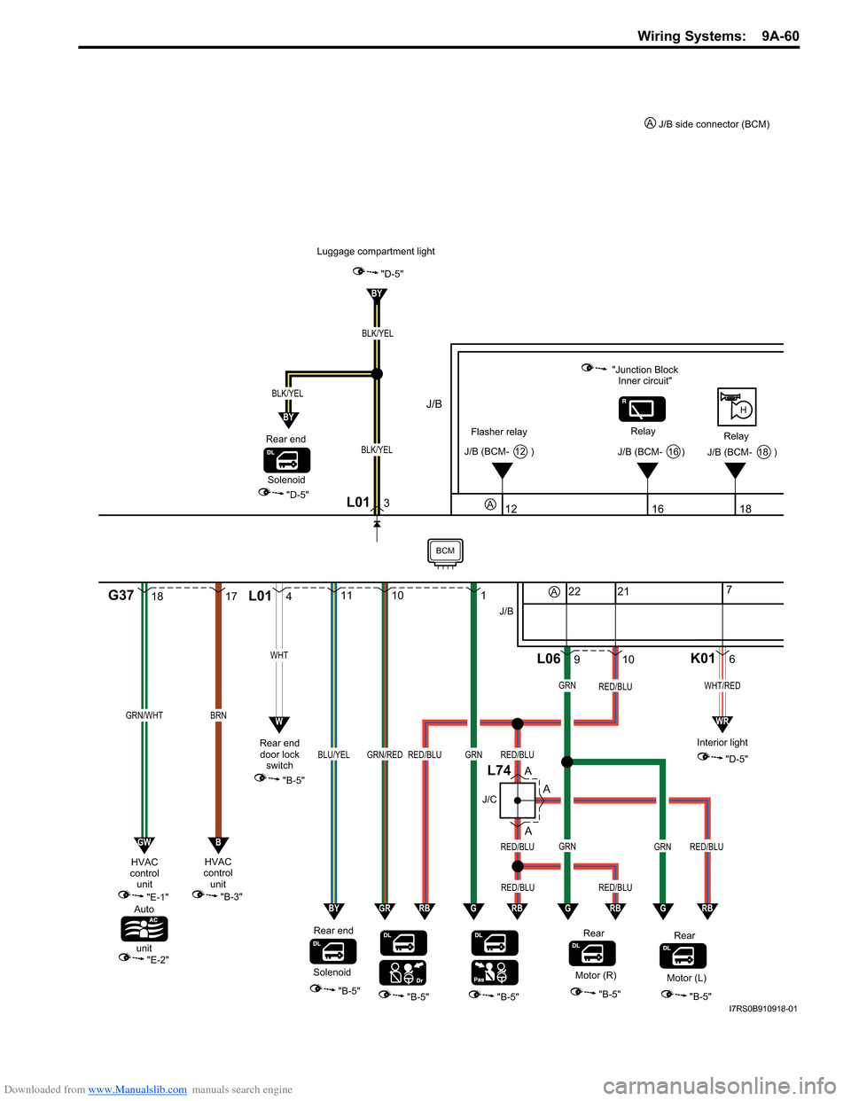
1817
GRN/WHTBRN
"E-1"
"E-2"
HVAC
control unit
Auto
unit
G37
Flasher relay Relay
Relay
H
12
"Junction Block
Inner circuit"
J/B (BCM- 12 )J/B (BCM- 18 )
1618
J/B (BCM- 16 )
J/B
"B-5""B-5""B-5""B-5"
11
9
L06
22
10
21
Rear
J/B
GRN
GRN
RED/BLU
RED/BLURED/BLU
RED/BLUGRNRED/BLU
GRN
110
GRN/REDRED/BLURED/BLUBLU/YEL
Rear end
L014
WHT
Rear end
door lock switch
3
"D-5"
BLK/YEL
L01
Luggage compartment light
7
6K01
Interior light
"D-5"
WHT/RED
WR
J/B side connector (BCM)
A
A
A
BY
GWB
W
BYGRRBGGRBGRBGRB
"B-5"
SolenoidMotor (R)
"B-5"
Rear
Motor (L)
"B-3"
HVAC
control unit
BCM
BLK/YEL
BY
BLK/YEL
"D-5"
Solenoid
Rear end
A
A
A
J/C
L74
I7RS0B910918-01