engine and emission control system check SUZUKI SWIFT 2008 2.G Service Manual PDF
[x] Cancel search | Manufacturer: SUZUKI, Model Year: 2008, Model line: SWIFT, Model: SUZUKI SWIFT 2008 2.GPages: 1496, PDF Size: 34.44 MB
Page 216 of 1496
Downloaded from www.Manualslib.com manuals search engine 1A-166 Engine General Information and Diagnosis:
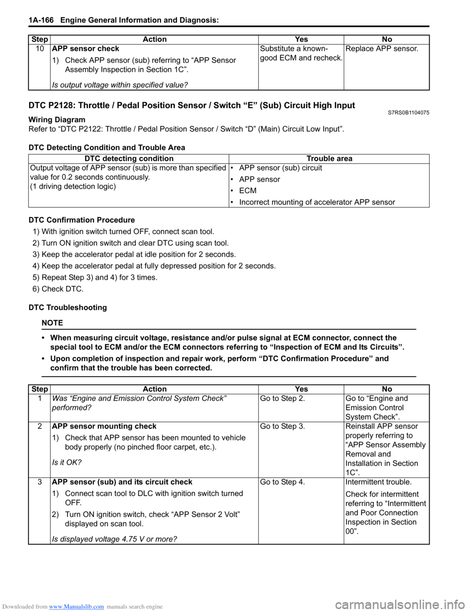
DTC P2128: Throttle / Pedal Position Sensor / Switch “E” (Sub) Circuit High InputS7RS0B1104075
Wiring Diagram
Refer to “DTC P2122: Throttle / Pedal Position Sensor / Switch “D” (Main) Circuit Low Input”.
DTC Detecting Condition and Trouble Area
DTC Confirmation Procedure 1) With ignition switch turned OFF, connect scan tool.
2) Turn ON ignition switch and clear DTC using scan tool.
3) Keep the accelerator pedal at idle position for 2 seconds.
4) Keep the accelerator pedal at fully depressed position for 2 seconds.
5) Repeat Step 3) and 4) for 3 times.
6) Check DTC.
DTC Troubleshooting
NOTE
• When measuring circuit voltage, resistance and/ or pulse signal at ECM connector, connect the
special tool to ECM and/or the ECM connectors re ferring to “Inspection of ECM and Its Circuits”.
• Upon completion of inspection and repair work, perform “DTC Confirmation Procedure” and confirm that the trouble has been corrected.
10 APP sensor check
1) Check APP sensor (sub) re ferring to “APP Sensor
Assembly Inspection in Section 1C”.
Is output voltage within specified value? Substitute a known-
good ECM and recheck.
Replace APP sensor.
Step Action Yes No
DTC detecting condition
Trouble area
Output voltage of APP sensor (s ub) is more than specified
value for 0.2 seconds continuously.
(1 driving detection logic) • APP sensor (sub) circuit
• APP sensor
•ECM
• Incorrect mounting of
accelerator APP sensor
Step Action YesNo
1 Was “Engine and Emission Control System Check”
performed? Go to Step 2.
Go to “Engine and
Emission Control
System Check”.
2 APP sensor mounting check
1) Check that APP sensor has been mounted to vehicle
body properly (no pinched floor carpet, etc.).
Is it OK? Go to Step 3.
Reinstall APP sensor
properly referring to
“APP Sensor Assembly
Removal and
Installation in Section
1C”.
3 APP sensor (sub) and its circuit check
1) Connect scan tool to DLC with ignition switch turned
OFF.
2) Turn ON ignition switch, check “APP Sensor 2 Volt” displayed on scan tool.
Is displayed voltage 4.75 V or more? Go to Step 4.
Intermittent trouble.
Check for intermittent
referring to “Intermittent
and Poor Connection
Inspection in Section
00”.
Page 219 of 1496
Downloaded from www.Manualslib.com manuals search engine Engine General Information and Diagnosis: 1A-169
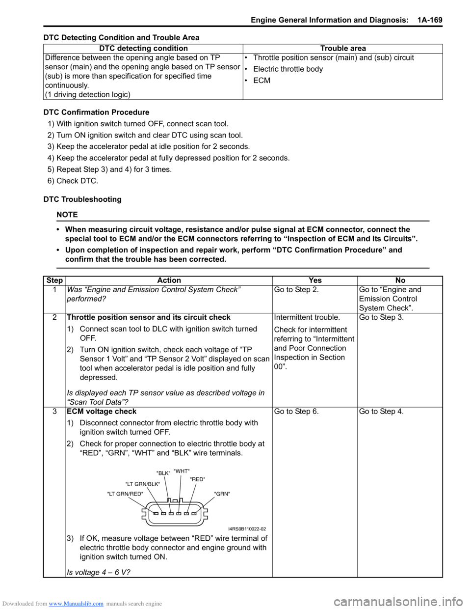
DTC Detecting Condition and Trouble Area
DTC Confirmation Procedure1) With ignition switch turned OFF, connect scan tool.
2) Turn ON ignition switch and clear DTC using scan tool.
3) Keep the accelerator pedal at idle position for 2 seconds.
4) Keep the accelerator pedal at fully depressed position for 2 seconds.
5) Repeat Step 3) and 4) for 3 times.
6) Check DTC.
DTC Troubleshooting
NOTE
• When measuring circuit voltage, resistance and/ or pulse signal at ECM connector, connect the
special tool to ECM and/or the ECM connectors re ferring to “Inspection of ECM and Its Circuits”.
• Upon completion of inspection and repair work, perform “DTC Confirmation Procedure” and confirm that the trouble has been corrected.
DTC detecting condition Trouble area
Difference between the opening angle based on TP
sensor (main) and the opening angle based on TP sensor
(sub) is more than specif ication for specified time
continuously.
(1 driving detection logic) • Throttle position sensor (main) and (sub) circuit
• Electric throttle body
•ECM
Step
Action YesNo
1 Was “Engine and Emission Control System Check”
performed? Go to Step 2.
Go to “Engine and
Emission Control
System Check”.
2 Throttle position sensor and its circuit check
1) Connect scan tool to DLC with ignition switch turned
OFF.
2) Turn ON ignition switch, check each voltage of “TP Sensor 1 Volt” and “TP Sensor 2 Volt” displayed on scan
tool when accelerator pedal is idle position and fully
depressed.
Is displayed each TP sensor value as described voltage in
“Scan Tool Data”? Intermittent trouble.
Check for intermittent
referring to “Intermittent
and Poor Connection
Inspection in Section
00”.
Go to Step 3.
3 ECM voltage check
1) Disconnect connector from electric throttle body with
ignition switch turned OFF.
2) Check for proper connection to electric throttle body at “RED”, “GRN”, “WHT” and “BLK” wire terminals.
3) If OK, measure voltage between “RED” wire terminal of electric throttle body connector and engine ground with
ignition switch turned ON.
Is voltage 4 – 6 V? Go to Step 6.
Go to Step 4.
"GRN"
"RED"
"WHT"
"BLK"
"LT GRN/BLK"
"LT GRN/RED"
I4RS0B110022-02
Page 222 of 1496
Downloaded from www.Manualslib.com manuals search engine 1A-172 Engine General Information and Diagnosis:
DTC Troubleshooting
NOTE
• When measuring circuit voltage, resistance and/or pulse signal at ECM connector, connect the
special tool to ECM and/or the ECM connectors re ferring to “Inspection of ECM and Its Circuits”.
• Upon completion of inspection and repair work, perform “DTC Confirmation Procedure” and confirm that the trouble has been corrected.
Step Action YesNo
1 Was “Engine and Emission Control System Check”
performed? Go to Step 2.
Go to “Engine and
Emission Control
System Check”.
2 APP sensor and its circuit check
1) Connect scan tool to DLC with ignition switch turned
OFF.
2) Turn ON ignition switch.
3) Check each voltage of “APP Sensor 1 Volt” and “APP Sensor 2 Volt” displayed on scan tool when accelerator
pedal is idle position and fully depressed.
Is displayed each APP sensor value as described voltage in
“Scan Tool Data”? Intermittent trouble.
Check for intermittent
referring to “Intermittent
and Poor Connection
Inspection in Section
00”.
Go to Step 3.
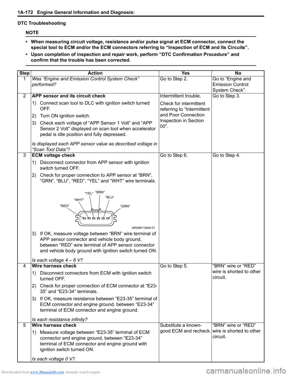
3 ECM voltage check
1) Disconnect connector from APP sensor with ignition
switch turned OFF.
2) Check for proper connection to APP sensor at “BRN”, “GRN”, “BLU”, “RED”, “YEL” and “WHT” wire terminals.
3) If OK, measure voltage between “BRN” wire terminal of APP sensor connector and vehicle body ground,
between “RED” wire terminal of APP sensor connector
and vehicle body ground with ignition switch turned ON.
Is each voltage 4 – 6 V? Go to Step 6.
Go to Step 4.
4 Wire harness check
1) Disconnect connectors from ECM with ignition switch
turned OFF.
2) Check for proper connection of ECM connector at “E23- 35” and “E23-34” terminals.
3) If OK, measure resistance between “E23-35” terminal of ECM connector and engine ground, between “E23-34”
terminal of ECM connector and engine ground.
Is each resistance infinity? Go to Step 5.
“BRN” wire or “RED”
wire is shorted to other
circuit.
5 Wire harness check
1) Measure voltage between “E23-35” terminal of ECM
connector and engine ground, between “E23-34”
terminal of ECM connector and engine ground with
ignition switch turned ON.
Is each voltage 0 V? Substitute a known-
good ECM and recheck.
“BRN” wire or “RED”
wire is shorted to other
circuit.
"GRN"
"BLU"
"BRN"
"YEL"
"WHT"
"RED"
I4RS0B110048-01
Page 224 of 1496
Downloaded from www.Manualslib.com manuals search engine 1A-174 Engine General Information and Diagnosis:
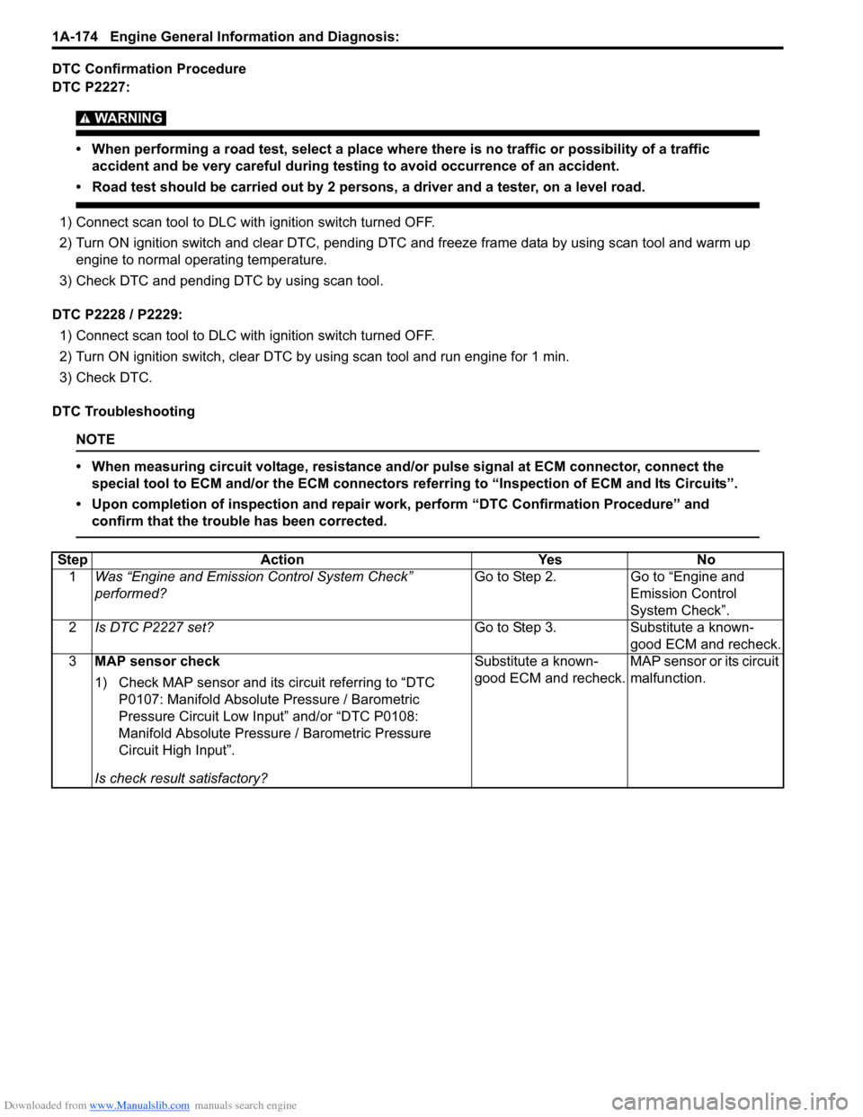
DTC Confirmation Procedure
DTC P2227:
WARNING!
• When performing a road test, select a place where there is no traffic or possibility of a traffic accident and be very careful during testing to avoid occurrence of an accident.
• Road test should be carried out by 2 persons, a driver and a tester, on a level road.
1) Connect scan tool to DLC with ignition switch turned OFF.
2) Turn ON ignition switch and clear DTC, pending DTC and freeze frame data by using scan tool and warm up
engine to normal operating temperature.
3) Check DTC and pending DTC by using scan tool.
DTC P2228 / P2229: 1) Connect scan tool to DLC with ignition switch turned OFF.
2) Turn ON ignition switch, clear DTC by using scan tool and run engine for 1 min.
3) Check DTC.
DTC Troubleshooting
NOTE
• When measuring circuit voltage, resistance and/ or pulse signal at ECM connector, connect the
special tool to ECM and/or the ECM connectors re ferring to “Inspection of ECM and Its Circuits”.
• Upon completion of inspection and repair work, perform “DTC Confirmation Procedure” and confirm that the trouble has been corrected.
Step Action YesNo
1 Was “Engine and Emission Control System Check”
performed? Go to Step 2.
Go to “Engine and
Emission Control
System Check”.
2 Is DTC P2227 set? Go to Step 3.Substitute a known-
good ECM and recheck.
3 MAP sensor check
1) Check MAP sensor and its circuit referring to “DTC
P0107: Manifold Absolute Pressure / Barometric
Pressure Circuit Low Input” and/or “DTC P0108:
Manifold Absolute Pressure / Barometric Pressure
Circuit High Input”.
Is check result satisfactory? Substitute a known-
good ECM and recheck.
MAP sensor or its circuit
malfunction.
Page 266 of 1496
Downloaded from www.Manualslib.com manuals search engine 1A-216 Engine General Information and Diagnosis:
Repair Instructions
Idle Speed and IAC Throttle Valve Opening
Inspection
S7RS0B1106001
Before idle speed check, make sure of the following.
• Lead wires and hoses of electronic fuel injection and engine and emission control systems are connected
securely.
• Valve lash is checked according to maintenance schedule.
• Ignition timing is within specification.
• All accessories (wipers, heater, lights, A/C, etc.) are out of service.
• Air cleaner has been properly installed and is in good condition.
• No abnormal air drawn in from air intake system.
After all items are confirmed, check idle speed and IAC
duty as follows.
NOTE
Before starting engine, place transmission
gear shift lever in “Neutral” (shift selector
lever to “P” range for A/T vehicle), and set
parking brake and block drive wheels.
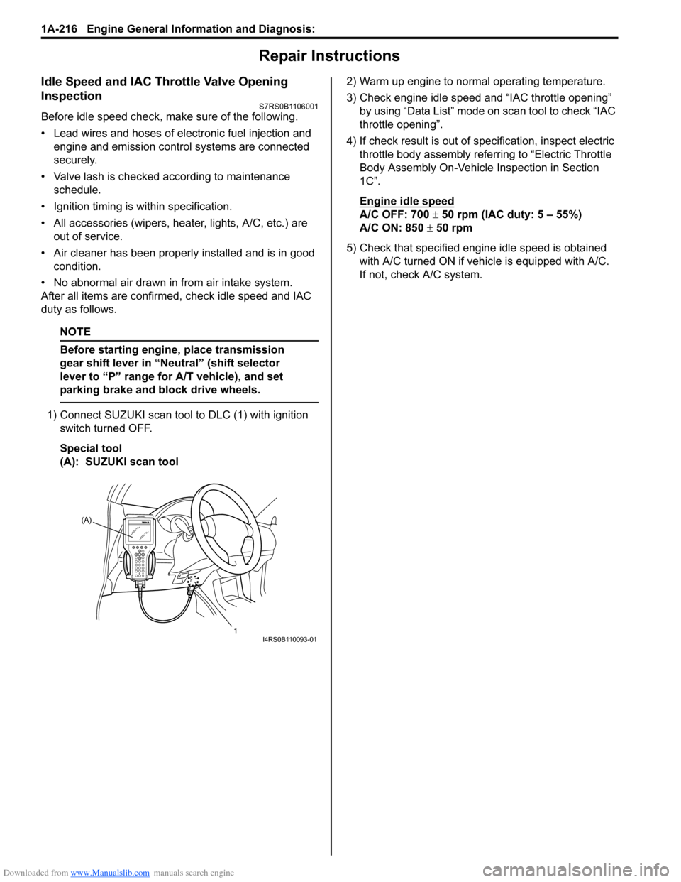
1) Connect SUZUKI scan tool to DLC (1) with ignition
switch turned OFF.
Special tool
(A): SUZUKI scan tool 2) Warm up engine to normal operating temperature.
3) Check engine idle speed and “IAC throttle opening”
by using “Data List” mode on scan tool to check “IAC
throttle opening”.
4) If check result is out of sp ecification, inspect electric
throttle body assembly referring to “Electric Throttle
Body Assembly On-Vehicle Inspection in Section
1C”.
Engine idle speed
A/C OFF: 700 ± 50 rpm (IAC duty: 5 – 55%)
A/C ON: 850 ± 50 rpm
5) Check that specified engine idle speed is obtained with A/C turned ON if vehi cle is equipped with A/C.
If not, check A/C system.
(A)
1
I4RS0B110093-01
Page 268 of 1496
Downloaded from www.Manualslib.com manuals search engine 1B-1 Aux. Emission Control Devices:
Engine
Aux. Emission Control Devices
Diagnostic Information and Procedures
EGR System InspectionS7RS0B1204001
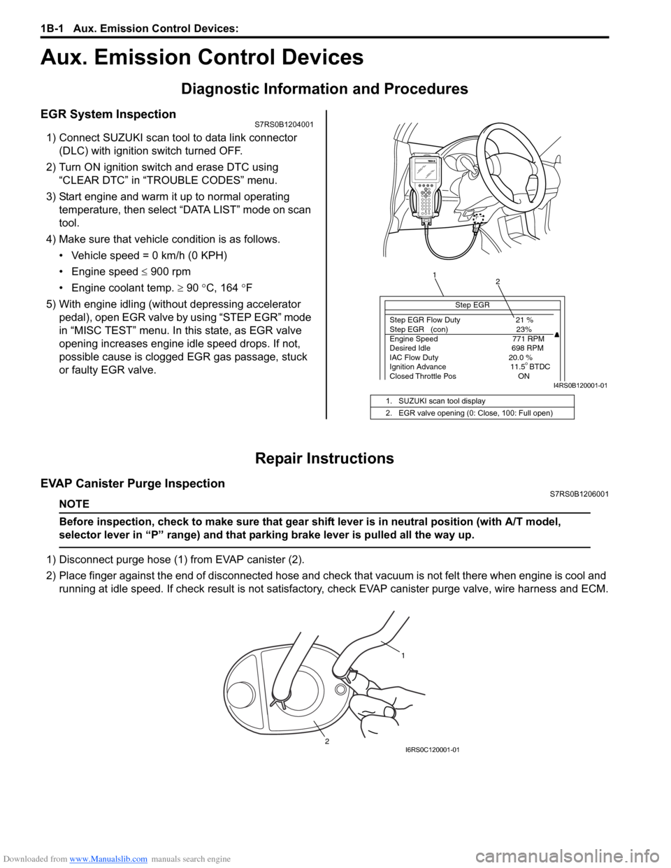
1) Connect SUZUKI scan tool to data link connector (DLC) with ignition switch turned OFF.
2) Turn ON ignition switch and erase DTC using “CLEAR DTC” in “TROUBLE CODES” menu.
3) Start engine and warm it up to normal operating temperature, then select “DATA LIST” mode on scan
tool.
4) Make sure that vehicle condition is as follows.
• Vehicle speed = 0 km/h (0 KPH)
• Engine speed ≤ 900 rpm
• Engine coolant temp. ≥ 90 °C, 164 °F
5) With engine idling (without depressing accelerator pedal), open EGR valve by using “STEP EGR” mode
in “MISC TEST” menu. In this state, as EGR valve
opening increases engine idle speed drops. If not,
possible cause is clogged EGR gas passage, stuck
or faulty EGR valve.
Repair Instructions
EVAP Canister Purge InspectionS7RS0B1206001
NOTE
Before inspection, check to make sure that gear shift lever is in neutral position (with A/T model,
selector lever in “P” range) and that parking brake lever is pulled all the way up.
1) Disconnect purge hose (1) from EVAP canister (2).
2) Place finger against the end of disconne cted hose and check that vacuum is not felt there when engine is cool and
running at idle speed. If check result is not satisfacto ry, check EVAP canister purge valve, wire harness and ECM.
1. SUZUKI scan tool display
2. EGR valve opening (0: Close, 100: Full open)
Step EGR
Step EGR Flow Duty 21 %
Step EGR (con) 23%
Engine Speed 771 RPM
Desired Idle 698 RPM
IAC Flow Duty 20.0 %
Ignition Advance 11.5 BTDC
Closed Throttle Pos ON
1 2
I4RS0B120001-01
1
2
I6RS0C120001-01
Page 396 of 1496
Downloaded from www.Manualslib.com manuals search engine 1H-4 Ignition System:
Diagnostic Information and Procedures
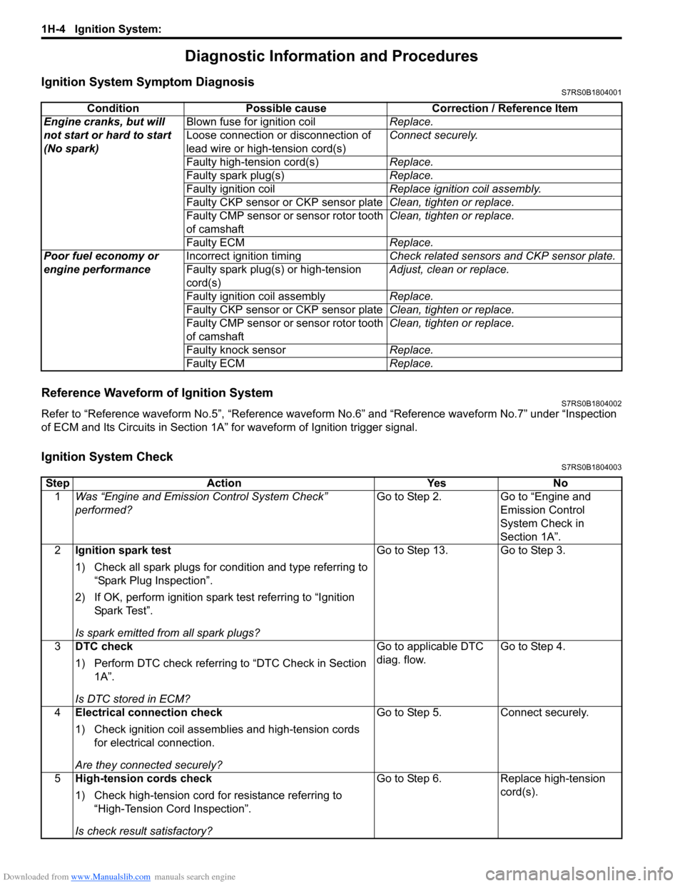
Ignition System Symptom DiagnosisS7RS0B1804001
Reference Waveform of Ignition SystemS7RS0B1804002
Refer to “Reference waveform No.5”, “Reference waveform No.6” and “Reference waveform No.7” under “Inspection
of ECM and Its Circuits in Section 1A” for waveform of Ignition trigger signal.
Ignition System CheckS7RS0B1804003
Condition Possible cause Correction / Reference Item
Engine cranks, but will
not start or hard to start
(No spark) Blown fuse for ignition coil
Replace.
Loose connection or disconnection of
lead wire or high-tension cord(s) Connect securely.
Faulty high-tension cord(s) Replace.
Faulty spark plug(s) Replace.
Faulty ignition coil Replace ignition coil assembly.
Faulty CKP sensor or CKP sensor plate Clean, tighten or replace.
Faulty CMP sensor or sensor rotor tooth
of camshaft Clean, tighten or replace.
Faulty ECM Replace.
Poor fuel economy or
engine performance Incorrect ignition timing
Check related sensors and CKP sensor plate.
Faulty spark plug(s) or high-tension
cord(s) Adjust, clean or replace.
Faulty ignition coil assembly Replace.
Faulty CKP sensor or CKP sensor plate Clean, tighten or replace.
Faulty CMP sensor or sensor rotor tooth
of camshaft Clean, tighten or replace.
Faulty knock sensor Replace.
Faulty ECM Replace.
StepAction YesNo
1 Was “Engine and Emission Control System Check”
performed? Go to Step 2.
Go to “Engine and
Emission Control
System Check in
Section 1A”.
2 Ignition spark test
1) Check all spark plugs for condition and type referring to
“Spark Plug Inspection”.
2) If OK, perform ignition spark test referring to “Ignition Spar k Tes t”.
Is spark emitted from all spark plugs? Go to Step 13. Go to Step 3.
3 DTC check
1) Perform DTC check referring to “DTC Check in Section
1A”.
Is DTC stored in ECM? Go to applicable DTC
diag. flow.
Go to Step 4.
4 Electrical connection check
1) Check ignition coil assemblies and high-tension cords
for electrical connection.
Are they connected securely? Go to Step 5.
Connect securely.
5 High-tension cords check
1) Check high-tension cord for resistance referring to
“High-Tension Cord Inspection”.
Is check result satisfactory? Go to Step 6.
Replace high-tension
cord(s).
Page 424 of 1496
Downloaded from www.Manualslib.com manuals search engine 1K-1 Exhaust System:
Engine
Exhaust System
General Description
Exhaust System DescriptionS7RS0B1B01001
The exhaust system consists of an exhaust manifold, three-way catalytic converter (TWC) in catalyst case, exhaust
pipes, a muffler and seals, gasket and etc.
The three-way catalytic converter is an emission control device added to the exhaust system to lower the levels of
Hydrocarbon (HC), Carbon Monoxide (CO), and Oxides of Nitrogen (NOx) pollutants in the exhaust gas.
Diagnostic Information and Procedures
Exhaust System CheckS7RS0B1B04001
WARNING!
To avoid the danger of being burned, do not touch the exhaust system when the system is hot. Any
service on the exhaust system should be performed when the system is cool.
At every interval of periodic maintenance service, and when vehicle is raised for other service, check exhaust system
as follows:
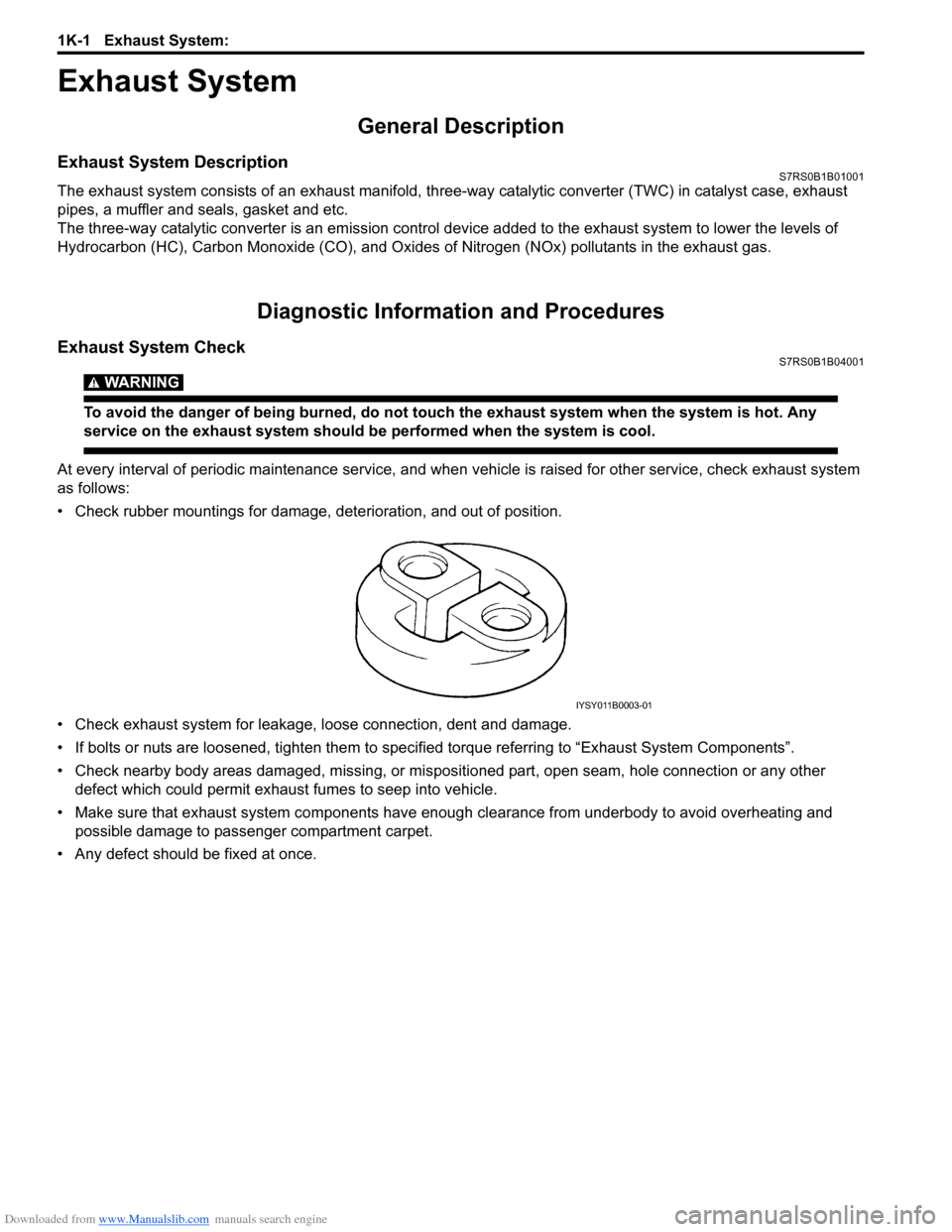
• Check rubber mountings for damage, deterioration, and out of position.
• Check exhaust system for leakage, loose connection, dent and damage.
• If bolts or nuts are loosened, tighten them to specified torque referring to “Exhaust System Components”.
• Check nearby body areas damaged, missing, or mispositio ned part, open seam, hole connection or any other
defect which could permit exhaust fumes to seep into vehicle.
• Make sure that exhaust system components have enough clearance from underbody to avoid overheating and
possible damage to passenger compartment carpet.
• Any defect should be fixed at once.
IYSY011B0003-01
Page 1446 of 1496
Downloaded from www.Manualslib.com manuals search engine 10C-3 Immobilizer Control System:
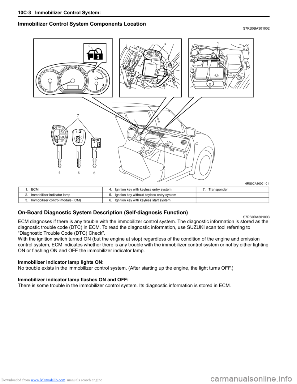
Immobilizer Control System Components LocationS7RS0BA301002
On-Board Diagnostic System Description (Self-diagnosis Function)S7RS0BA301003
ECM diagnoses if there is any trouble with the immobilizer control system. The diagnostic information is stored as the
diagnostic trouble code (DTC) in ECM. To read the di agnostic information, use SUZUKI scan tool referring to
“Diagnostic Trouble Code (DTC) Check”.
With the ignition switch turned ON (but the engine at stop) regardless of the condition of the engine and emission
control system, ECM indicates whether ther e is any trouble with the immobilizer control system or not by either lighting
ON or flashing ON and OFF t he immobilizer indicator lamp.
Immobilizer indicator lamp lights ON:
No trouble exists in the immobilizer control system. (After starting up the engine, the light turns OFF.)
Immobilizer indicator lamp flashes ON and OFF:
There is some trouble in the immo bilizer control system. Its diagnostic information is stored in ECM.
13
4
56
7
2
I6RS0CA30001-01
1. ECM 4. Ignition key with keyless entry system 7. Transponder
2. Immobilizer indicator lamp 5. Ignition key without keyless entry system
3. Immobilizer control module (ICM) 6. Ignition key with keyless start system
Page 1448 of 1496
Downloaded from www.Manualslib.com manuals search engine 10C-5 Immobilizer Control System:
Diagnostic Information and Procedures
Immobilizer Control System CheckS7RS0BA304001
Diagnostic Trouble Code (DTC) CheckS7RS0BA304002
NOTE
To know how to use SUZUKI scan tool in
detail, refer to its operator’s manual.
Using Scan Tool
1) Turn the ignition switch to OFF position.
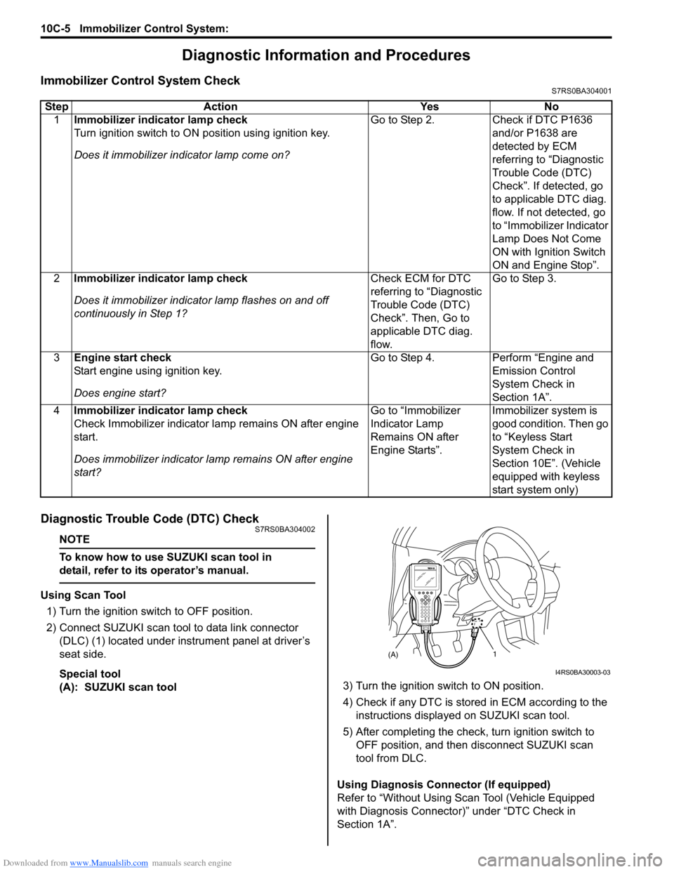
2) Connect SUZUKI scan tool to data link connector (DLC) (1) located under instrument panel at driver’s
seat side.
Special tool
(A): SUZUKI scan tool 3) Turn the ignition switch to ON position.
4) Check if any DTC is stored
in ECM according to the
instructions displayed on SUZUKI scan tool.
5) After completing the check, turn ignition switch to
OFF position, and then di sconnect SUZUKI scan
tool from DLC.
Using Diagnosis Connector (If equipped)
Refer to “Without Using Scan Tool (Vehicle Equipped
with Diagnosis Connector)” under “DTC Check in
Section 1A”.
Step Action Yes No
1 Immobilizer indicator lamp check
Turn ignition switch to ON position using ignition key.
Does it immobilizer in dicator lamp come on? Go to Step 2.
Check if DTC P1636
and/or P1638 are
detected by ECM
referring to “Diagnostic
Trouble Code (DTC)
Check”. If detected, go
to applicable DTC diag.
flow. If not detected, go
to “Immobilizer Indicator
Lamp Does Not Come
ON with Ignition Switch
ON and Engine Stop”.
2 Immobilizer indicator lamp check
Does it immobilizer indicato r lamp flashes on and off
continuously in Step 1? Check ECM for DTC
referring to “Diagnostic
Trouble Code (DTC)
Check”. Then, Go to
applicable DTC diag.
flow.Go to Step 3.
3 Engine start check
Start engine using ignition key.
Does engine start? Go to Step 4.
Perform “Engine and
Emission Control
System Check in
Section 1A”.
4 Immobilizer indicator lamp check
Check Immobilizer indicator la mp remains ON after engine
start.
Does immobilizer indicator la mp remains ON after engine
start? Go to “Immobilizer
Indicator Lamp
Remains ON after
Engine Starts”.
Immobilizer system is
good condition. Then go
to “Keyless Start
System Check in
Section 10E”. (Vehicle
equipped with keyless
start system only)
(A)1
I4RS0BA30003-03