1e-2 SUZUKI SWIFT 2008 2.G Service Workshop Manual
[x] Cancel search | Manufacturer: SUZUKI, Model Year: 2008, Model line: SWIFT, Model: SUZUKI SWIFT 2008 2.GPages: 1496, PDF Size: 34.44 MB
Page 48 of 1496
Downloaded from www.Manualslib.com manuals search engine 1-iv Table of Contents
Engine Lubrication System.....................1E-1
General Description ............................................. 1E-1
Engine Lubrication Description ........................... 1E-1
Diagnostic Information and Procedures ............ 1E-2 Oil Pressure Check ............................................. 1E-2
Repair Instructions ........... ................................... 1E-3
Heat Exchanger Components ............................. 1E-3
Heat Exchanger On-Vehicle Inspection .............. 1E-4
Heat Exchanger Removal and Installation .......... 1E-4
Oil Pan and Oil Pump Strainer Components....... 1E-5
Oil Pan and Oil Pump Strainer Removal and
Installation ......................................................... 1E-5
Oil Pan and Oil Pump Stra iner Cleaning ............. 1E-7
Oil Pump Components ........................................ 1E-8
Oil Pump Removal and Installation ..................... 1E-8
Oil Pump Disassembly and Reassembly ............ 1E-8
Oil Pump Inspection ............................................ 1E-9
Specifications .... ................................................. 1E-11
Tightening Torque Specifications ...................... 1E-11
Special Tools and Equipmen t ........................... 1E-11
Recommended Service Material ....................... 1E-11
Special Tool ...................................................... 1E-11
Engine Cooling System ..... ...................... 1F-1
General Description .......... ................................... 1F-1
Cooling System Descriptio n ................................ 1F-1
Coolant Description ............................................. 1F-1
Schematic and Routing Diagram ........................ 1F-2 Coolant Circulation .............................................. 1F-2
Diagnostic Information and Procedures ............ 1F-4 Engine Cooling Symptom Diagnosis ................... 1F-4
Repair Instructions ........... ................................... 1F-5
Cooling System Components.............................. 1F-5
Coolant Level Check ........................................... 1F-6
Engine Cooling System Inspection and Cleaning ............................................................ 1F-6
Cooling System Draining.. ................................... 1F-6
Cooling System Flush and Refill ......................... 1F-7
Cooling Water Pipes or Hoses Removal and Installation ......................................................... 1F-7
Thermostat Removal and In stallation.................. 1F-8
Thermostat Inspection......................................... 1F-8
Radiator Cooling Fan Motor On-Vehicle Inspection .......................................................... 1F-9
Radiator Cooling Fan Rela y Inspection............... 1F-9
Radiator Cooling Fan Removal and Installation ....................................................... 1F-10
Radiator On-Vehicle Inspection and Cleaning .. 1F-10
Radiator Removal and Inst allation .................... 1F-10
Water Pump Removal and In stallation .............. 1F-11
Water Pump Inspection ..................................... 1F-11
Specifications .... ................................................. 1F-12
Tightening Torque Specifications ...................... 1F-12
Special Tools and Equipmen t ........................... 1F-12
Recommended Service Material ....................... 1F-12
Fuel System ................... .......................... 1G-1
Precautions.......................................................... 1G-1 Precautions on Fuel System Service ................. 1G-1
General Description ............................................ 1G-1 Fuel System Description .................................... 1G-1
Fuel Delivery System Description ...................... 1G-1
Fuel Pump Description ....................................... 1G-2
Schematic and Routing Diagram ....................... 1G-2 Fuel Delivery System Diag ram........................... 1G-2
Diagnostic Information and Procedures ........... 1G-2 Fuel Pressure Inspection ................................... 1G-2
Fuel Cut Operation Inspection ........................... 1G-3
Repair Instructions ............ ................................. 1G-4
Fuel System Components .................................. 1G-4
Fuel Hose Disconnecting and Reconnecting ..... 1G-5
Fuel Pressure Relief Procedure ......................... 1G-7
Fuel Leakage Check Procedure......................... 1G-7
Fuel Lines On-Vehicle Inspection ...................... 1G-7
Fuel Pipe Removal and Installation.................... 1G-7
Fuel Injector On-Vehicle Inspection ................... 1G-8
Fuel Injector Removal and Installation ............... 1G-8
Fuel Injector Inspection ...................................... 1G-9
Fuel Filler Cap Inspection . ............................... 1G-10
Fuel Tank Inlet Valve Removal and Installation ...................................................... 1G-11
Fuel Tank Inlet Valve Inspection ...................... 1G-12
Fuel Tank Removal and Installation ................. 1G-12
Fuel Tank Inspection ........................................ 1G-13
Fuel Tank Purging Procedure .......................... 1G-14
Fuel Pump On-Vehicle Inspection.................... 1G-14
Fuel Pump Assembly Removal and Installation ...................................................... 1G-14
Main Fuel Level Sensor Removal and Installation ...................................................... 1G-15
Fuel Pump Inspection ...................................... 1G-16
Specifications ..................... ............................... 1G-16
Tightening Torque Specifications ..................... 1G-16
Special Tools and Equipmen t .......................... 1G-17
Special Tool ..................................................... 1G-17
Ignition System .............. .......................... 1H-1
General Description .............................................1H-1
Ignition System Construction ..............................1H-1
Schematic and Routing Diagram ........................1H-2 Ignition System Wiring Circuit Diagram...............1H-2
Component Location ............ ...............................1H-3
Ignition System Components Location................1H-3
Diagnostic Information and Procedures ............1H-4 Ignition System Symptom Diagnosis...................1H-4
Reference Waveform of Ignition System.............1H-4
Ignition System Check ........................................1H-4
Ignition Spark Test ..............................................1H-6
Repair Instructions ............ ..................................1H-6
High-Tension Cord Removal and Installation......1H-6
High-Tension Cord Inspection.............................1H-7
Spark Plug Removal and Installation ..................1H-7
Spark Plug Inspection .........................................1H-7
Ignition Coil Assembly (Including ignitor)
Removal and Installation ...................................1H-8
Ignition Coil Assembly (Including ignitor)
Inspection ..........................................................1H-8
Page 354 of 1496
Downloaded from www.Manualslib.com manuals search engine 1E-2 Engine Lubrication System:
Diagnostic Information and Procedures
Oil Pressure CheckS7RS0B1504001
WARNING!
To avoid danger of being burned, do not
touch exhaust system when it is still hot.
NOTE
Prior to checking oil pressure, check the
following.
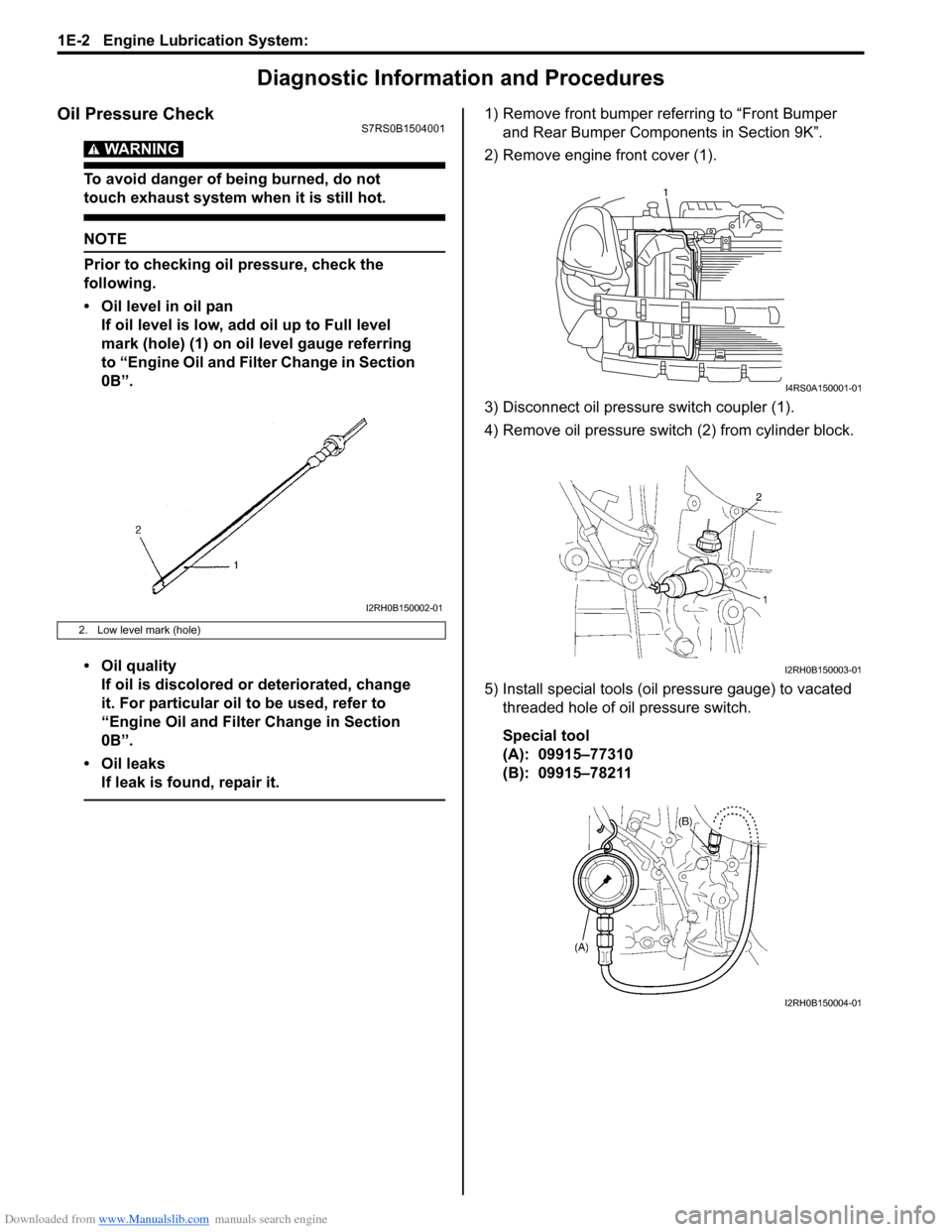
• Oil level in oil pan
If oil level is low, add oil up to Full level
mark (hole) (1) on oil level gauge referring
to “Engine Oil and Filter Change in Section
0B”.
• Oil quality If oil is discolored or deteriorated, change
it. For particular oil to be used, refer to
“Engine Oil and Filter Change in Section
0B”.
• Oil leaks If leak is found, repair it.
1) Remove front bumper referring to “Front Bumper and Rear Bumper Components in Section 9K”.
2) Remove engine front cover (1).
3) Disconnect oil pressure switch coupler (1).
4) Remove oil pressure swit ch (2) from cylinder block.
5) Install special tools (oil pressure gauge) to vacated threaded hole of oil pressure switch.
Special tool
(A): 09915–77310
(B): 09915–78211
2. Low level mark (hole)
I2RH0B150002-01
1
I4RS0A150001-01
I2RH0B150003-01
I2RH0B150004-01