Air con belt replacement SUZUKI SWIFT 2008 2.G Service Workshop Manual
[x] Cancel search | Manufacturer: SUZUKI, Model Year: 2008, Model line: SWIFT, Model: SUZUKI SWIFT 2008 2.GPages: 1496, PDF Size: 34.44 MB
Page 6 of 1496
Downloaded from www.Manualslib.com manuals search engine 00-1 Precautions:
Precautions
Precautions
Precautions
Precautions for Vehicles Equipped with a
Supplemental Restraint (Air Bag) System
S7RS0B0000001
WARNING!
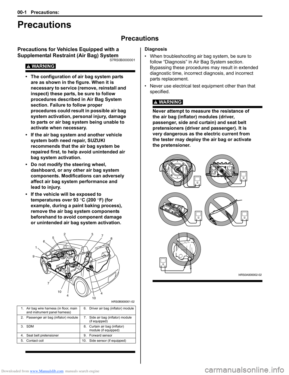
• The configuration of air bag system parts are as shown in the figure. When it is
necessary to service (remove, reinstall and
inspect) these parts, be sure to follow
procedures described in Air Bag System
section. Failure to follow proper
procedures could result in possible air bag
system activation, personal injury, damage
to parts or air bag system being unable to
activate when necessary.
• If the air bag system and another vehicle system both need repair, SUZUKI
recommends that the air bag system be
repaired first, to help avoid unintended air
bag system activation.
• Do not modify the steering wheel, dashboard, or any other air bag system
components. Modifications can adversely
affect air bag system performance and
lead to injury.
• If the vehicle will be exposed to temperatures over 93 °C (200 °F) (for
example, during a paint baking process),
remove the air bag system components
beforehand to avoid component damage
or unintended air bag system activation.
Diagnosis
• When troubleshooting air bag system, be sure to follow “Diagnosis” in Air Bag System section.
Bypassing these procedures may result in extended
diagnostic time, incorrect diagnosis, and incorrect
parts replacement.
• Never use electrical test equipment other than that specified.
WARNING!
Never attempt to measure the resistance of
the air bag (inflator) modules (driver,
passenger, side and curtain) and seat belt
pretensioners (driver and passenger). It is
very dangerous as the electric current from
the tester may deploy the air bag or activate
the pretensioner.
1. Air bag wire harness (in floor, main and instrument panel harness) 6. Driver air bag (inflator) module
2. Passenger air bag (inflator) module 7. Side air bag (inflator) module (if equipped)
3. SDM 8. Curtain air bag (inflator) module (if equipped)
4. Seat belt pretensioner 9. Forward sensor
5. Contact coil 10. Side sensor (if equipped)
1 2
3
4
4
5
6
7 7
8
9
10 10
I4RS0B000001-02
I4RS0A000002-02
Page 21 of 1496
Downloaded from www.Manualslib.com manuals search engine Table of Contents 0- i
0
Section 0
CONTENTS
General Information
General Information ................................ 0A-1
General Description ............................................. 0A-1
Abbreviations ...................................................... 0A-1
Symbols .............................................................. 0A-2
Wire Color Symbols ............................................ 0A-2
Fasteners Information ......................................... 0A-3
Vehicle Lifting Points ........................................... 0A-5
Engine Supporting Points ................................... 0A-7
Vehicle Identification Number ............................. 0A-7
Engine Identification Number .............................. 0A-7
Transmission Identification Number .................... 0A-7
Component Locatio n ........................................... 0A-8
Warning, Caution and Information Labels Location ............................................................ 0A-8
Maintenance and Lubricat ion ................. 0B-1
Precautions........................................................... 0B-1
Precautions for Maintenance and Lubrication ..... 0B-1
Scheduled Maintenance ...................................... 0B-1 Maintenance Schedule under Normal Driving Conditions ......................................................... 0B-1
Maintenance Recommended under Severe Driving Conditions ............................................. 0B-2
Repair Instructions .............................................. 0B-3 Accessory Drive Belt Inspection.......................... 0B-3
Accessory Drive Belt Repl acement ..................... 0B-4
Valve Lash (Clearance) Inspection ..................... 0B-4
Engine Oil and Filter Change .............................. 0B-4
Engine Coolant Change ...... ................................ 0B-5
Exhaust System Inspection ................................. 0B-6
Spark Plug Replacement .................................... 0B-6
Air Cleaner Filter Inspection ................................ 0B-6
Air Cleaner Filter Replac ement ........................... 0B-6 Fuel Lines and Connections Inspection .............. 0B-6
Fuel Filter Replacement ...................................... 0B-7
Fuel Tank Inspection ........................................... 0B-7
PCV Valve Inspection ......................................... 0B-7
Fuel Evaporative Emission Control System
Inspection .......................................................... 0B-7
Brake Discs and Pads Inspection ....................... 0B-7
Brake Hoses and Pipes Inspection ..................... 0B-7
Brake Fluid Inspection......................................... 0B-8
Brake Fluid Replacement .................................... 0B-8
Brake Lever and Cable Inspection ...................... 0B-8
Clutch Fluid Inspection ........................................ 0B-8
Tires Inspection ................................................... 0B-9
Wheel Discs Inspection ....................................... 0B-9
Wheel Bearing Inspection ................................... 0B-9
Suspension System Inspection ........................... 0B-9
Steering System Inspection .............................. 0B-10
Drive Shaft (Axle) Boots Inspection .................. 0B-10
Manual Transaxle Oil Inspection ....................... 0B-10
Manual Transaxle Oil Replacement .................. 0B-10
Automatic Transaxle Fluid Level Inspection...... 0B-11
Automatic Transaxle Fluid Replacement .......... 0B-11
Automatic Transaxle Fluid Cooler Hose Inspection ........................................................ 0B-11
All Latches, Hinges and Locks Inspection......... 0B-11
HVAC Air Filter (If Equipped) Inspection ........... 0B-12
HVAC Air Filter (If Equipped) Replacement ...... 0B-12
Final Inspection for Maint enance Service ......... 0B-12
Specifications .................... .................................0B-13
Tightening Torque Specifications ...................... 0B-13
Special Tools and Equipmen t ...........................0B-13
Recommended Fluids and Lubricants............... 0B-13
Special Tool ...................................................... 0B-14
Page 32 of 1496
Downloaded from www.Manualslib.com manuals search engine 0B-2 Maintenance and Lubrication:
NOTE
• “R”: Replace or change
• “I”: Inspect and correct, replace or lubricate if necessary
• For spark plugs, replace every 50,000 km if the local law requires.
• Periodic replacement of fuel filter is not necessary if it is not instructed in “Periodic Maintenance Schedule” section of the Owner’s manual. The scheduled maintenance varies depending on the
vehicle specification.
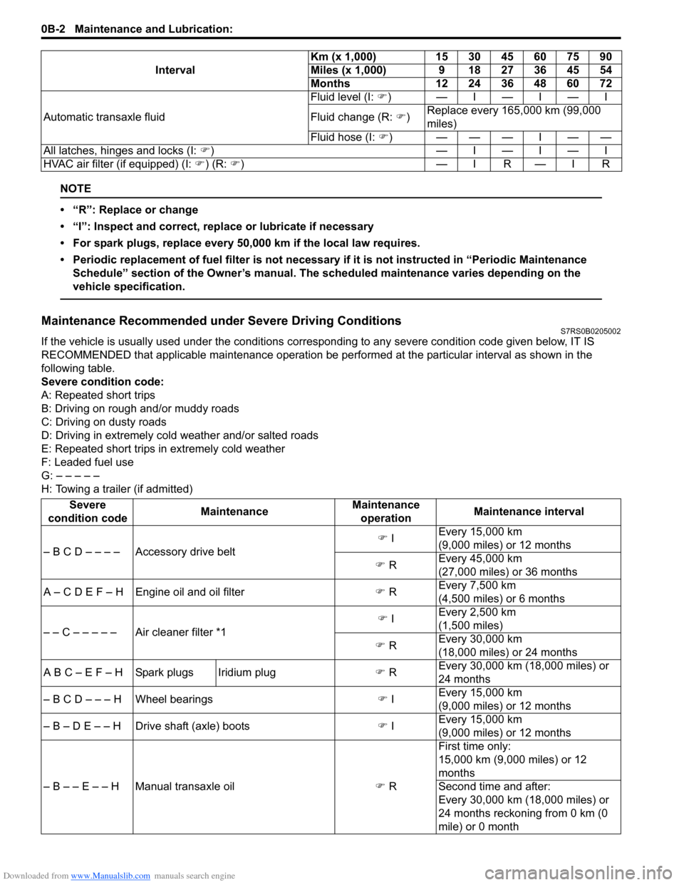
Maintenance Recommended under Severe Driving ConditionsS7RS0B0205002
If the vehicle is usually used under the conditions corres ponding to any severe condition code given below, IT IS
RECOMMENDED that applicable maintenance operation be per formed at the particular interval as shown in the
following table.
Severe condition code:
A: Repeated short trips
B: Driving on rough and/or muddy roads
C: Driving on dusty roads
D: Driving in extremely cold weather and/or salted roads
E: Repeated short trips in extremely cold weather
F: Leaded fuel use
G: – – – – –
H: Towing a trailer (if admitted) Automatic transaxle fluid
Fluid level (I:
�)) —I—I—I
Fluid change (R: �)) Replace every 165,000 km (99,000
miles)
Fluid hose (I: �))———I——
All latches, hinges and locks (I: �)) —I—I—I
HVAC air filter (if equipped) (I: �) ) (R: �))— IR — IR
Interval
Km (x 1,000)
15 30 45 60 75 90
Miles (x 1,000) 9 18 27 36 45 54
Months 12 24 36 48 60 72
Severe
condition code MaintenanceMaintenance
operation Maintenance interval
– B C D – – – – Accessory drive belt �)
I Every 15,000 km
(9,000 miles) or 12 months
�) R Every 45,000 km
(27,000 miles) or 36 months
A – C D E F – H Engine oil and oil filter �) R Every 7,500 km
(4,500 miles) or 6 months
– – C – – – – – Air cleaner filter *1 �)
I Every 2,500 km
(1,500 miles)
�) R Every 30,000 km
(18,000 miles) or 24 months
A B C – E F – H Spark plugs Iridium plug �) R Every 30,000 km (18,000 miles) or
24 months
– B C D – – – H Wheel bearings �) I Every 15,000 km
(9,000 miles) or 12 months
– B – D E – – H Drive shaft (axle) boots �) I Every 15,000 km
(9,000 miles) or 12 months
– B – – E – – H Manual transaxle oil �) R First time only:
15,000 km (9,000 miles) or 12
months
Second time and after:
Every 30,000 km (18,000 miles) or
24 months reckoning from 0 km (0
mile) or 0 month
Page 33 of 1496
Downloaded from www.Manualslib.com manuals search engine Maintenance and Lubrication: 0B-3
NOTE
• “I”: Inspect and correct or replace if necessary
• “R”: Replace or change
• *1: Inspect or replace more frequently if the vehicle is used under dusty conditions.
• *2: Clean or replace more frequently if the air from the air conditioning decreases.
Repair Instructions
Accessory Drive Belt InspectionS7RS0B0206001
WARNING!
All inspection and replacement are to be
performed with ENGINE NOT RUNNING.
Water Pump and Generator Drive Belt1) Disconnect negative (–) cable at battery.
2) Inspect belt for cracks, cu ts, deformation, wear and
cleanliness. If any defect exists, replace.
Check belt for tension.
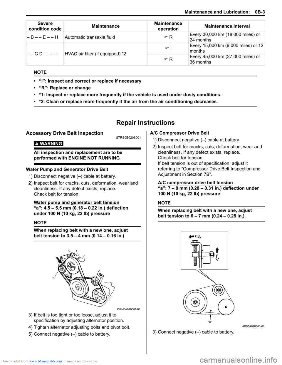
Water pump and generator belt tension
“a”: 4.5 – 5.5 mm (0.18 – 0.22 in.) deflection
under 100 N (10 kg, 22 lb) pressure
NOTE
When replacing belt with a new one, adjust
belt tension to 3.5 – 4 mm (0.14 – 0.16 in.)
3) If belt is too tight or too loose, adjust it to
specification by adjusting alternator position.
4) Tighten alternator adjusting bolts and pivot bolt.
5) Connect negative (–) cable to battery. A/C Compressor Drive Belt
1) Disconnect negative (–) cable at battery.
2) Inspect belt for cracks, cuts, deformation, wear and cleanliness. If any defect exists, replace.
Check belt for tension.
If belt tension is out of specification, adjust it
referring to “Compressor Dr ive Belt Inspection and
Adjustment in Section 7B”.
A/C compressor drive belt tension
“a”: 7 – 8 mm (0.28 – 0.31 in.) deflection under
100 N (10 kg, 22 lb) pressure
NOTE
When replacing belt with a new one, adjust
belt tension to 6 – 7 mm (0.24 – 0.28 in.).
3) Connect negative (–) cable to battery.
– B – – E – – H Automatic transaxle fluid
�) R Every 30,000 km (18,000 miles) or
24 months
– – C D – – – – HVAC air filter (if equipped) *2 �)
I Every 15,000 km (9,000 miles) or 12
months
�) R Every 45,000 km (27,000 miles) or
36 months
Severe
condition code MaintenanceMaintenance
operation Maintenance interval
I3RM0A020001-01
I4RS0A020001-01
Page 42 of 1496
Downloaded from www.Manualslib.com manuals search engine 0B-12 Maintenance and Lubrication:
HVAC Air Filter (If Equipped) InspectionS7RS0B0206032
1) Remove HVAC air filter from HVAC unit referring to
“HVAC Air Filter Removal and Installation (If
Equipped) in Section 7A”.
2) Check for dirt and dust. If HVAC air filter is excessively dirty, replace HVAC air filter with new
one. If not, go to next step.
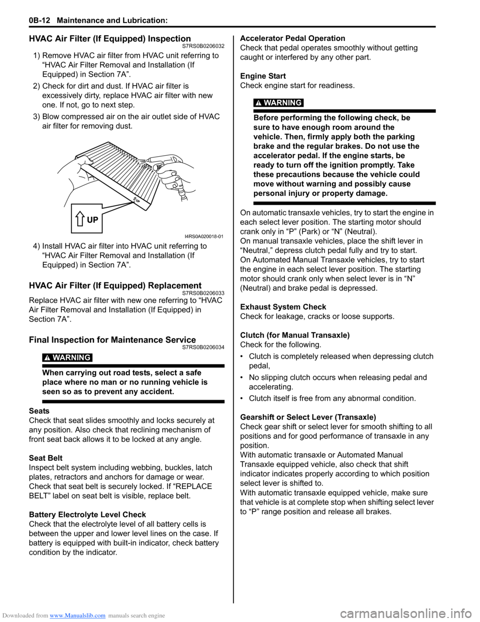
3) Blow compressed air on the air outlet side of HVAC air filter for removing dust.
4) Install HVAC air filter in to HVAC unit referring to
“HVAC Air Filter Removal and Installation (If
Equipped) in Section 7A”.
HVAC Air Filter (If Equipped) ReplacementS7RS0B0206033
Replace HVAC air filter with new one referring to “HVAC
Air Filter Removal and Installation (If Equipped) in
Section 7A”.
Final Inspection for Maintenance ServiceS7RS0B0206034
WARNING!
When carrying out road tests, select a safe
place where no man or no running vehicle is
seen so as to prevent any accident.
Seats
Check that seat slides smoot hly and locks securely at
any position. Also check that reclining mechanism of
front seat back allows it to be locked at any angle.
Seat Belt
Inspect belt system including webbing, buckles, latch
plates, retractors and anchors for damage or wear.
Check that seat belt is securely locked. If “REPLACE
BELT” label on seat belt is visible, replace belt.
Battery Electrolyte Level Check
Check that the electrolyte le vel of all battery cells is
between the upper and lower level lines on the case. If
battery is equipped with built-in indicator, check battery
condition by the indicator. Accelerator Pedal Operation
Check that pedal operates
smoothly without getting
caught or interfered by any other part.
Engine Start
Check engine start for readiness.
WARNING!
Before performing th e following check, be
sure to have enough room around the
vehicle. Then, firmly apply both the parking
brake and the regular brakes. Do not use the
accelerator pedal. If the engine starts, be
ready to turn off the ignition promptly. Take
these precautions because the vehicle could
move without warning and possibly cause
personal injury or property damage.
On automatic transaxle vehicles, try to start the engine in
each select lever position. The starting motor should
crank only in “P” (Park) or “N” (Neutral).
On manual transaxle vehicles, place the shift lever in
“Neutral,” depress clutch pedal fully and try to start.
On Automated Manual Transaxl e vehicles, try to start
the engine in each select le ver position. The starting
motor should crank only when select lever is in “N”
(Neutral) and brake pedal is depressed.
Exhaust System Check
Check for leakage, cracks or loose supports.
Clutch (for Manual Transaxle)
Check for the following.
• Clutch is completely released when depressing clutch pedal,
• No slipping clutch occurs when releasing pedal and accelerating.
• Clutch itself is free fr om any abnormal condition.
Gearshift or Select Lever (Transaxle)
Check gear shift or select lever for smooth shifting to all
positions and for good performance of transaxle in any
position.
With automatic transaxle or Automated Manual
Transaxle equipped vehicle, also check that shift
indicator indicates properly according to which position
select lever is shifted to.
With automatic transaxle equipped vehicle, make sure
that vehicle is at complete stop when shifting select lever
to “P” range position and release all brakes.
I4RS0A020018-01
Page 469 of 1496
Downloaded from www.Manualslib.com manuals search engine Wheels and Tires: 2D-2
Lower than recommended pressure can cause:
• Tire squeal on turns
• Hard Steering
• Rapid and uneven wear on the edges of the tread
• Tire rim bruises and rupture
• Tire cord breakage
• High tire temperature
• Reduced handling
• High fuel consumption
Replacement Tires
When replacement is necessary, the original equipment
type tire should be used. Refer to the Tire Placard.
Replacement tires should be of the same size, load
range and construction as those originally on the vehicle.
Use of any other size or type tire may affect ride,
handling, speedometer / odometer calibration, vehicle
ground clearance and tire or snow chain clearance to the
body and chassis.
It is recommended that new tires be installed in pairs on
the same axle. If necessary to replace only one tire, it
should be paired with the tire having the most tread, to
equalize braking traction.
WARNING!
Do not mix different types of tires on the
same vehicle such as radial, bias and bias-
belted tires except in emergencies, because
handling may be seriously affected and may
result in loss of control.
The metric term for tire infl ation pressure is the kilo
pascal (kPa). Tire pressures is usually printed in both
kPa and kgf/cm
2 on the “Tire Placard”.
Metric tire gauges are available from tool suppliers.
The chart, shown the table, converts commonly used
inflation pressures from kPa to kgf/cm
2 and psi.
Wheels DescriptionS7RS0B2401002
Wheel Maintenance
Wheel repairs that use welding, heating, or peening are
not approved. All damaged wheels should be replaced.
Replacement Wheels
Wheels must be replaced if they are bent, dented, have
excessive lateral or radial runout, air leak through welds,
have elongated bolt holes, if lug wheel bolts won’t stay
tight, or if they are heavily rusted. Wheels with greater
runout than shown in the following may cause
objectional vibrations.
Replacement wheels must be equivalent to the original
equipment wheels in load capacity, diameter, rim with
offset and mounting configuration. A wheel of improper
size or type may affect wheel and bearing life, brake
cooling, speedometer / odometer calibration, vehicle
ground clearance and tire clearance to body and
chassis.
How to Measure Wheel Runout
To measure the wheel runout, it is necessary to use an
accurate dial indicator. The tire may be on or off the
wheel. The wheel should be installed to the wheel
balancer of the like for proper measurement.
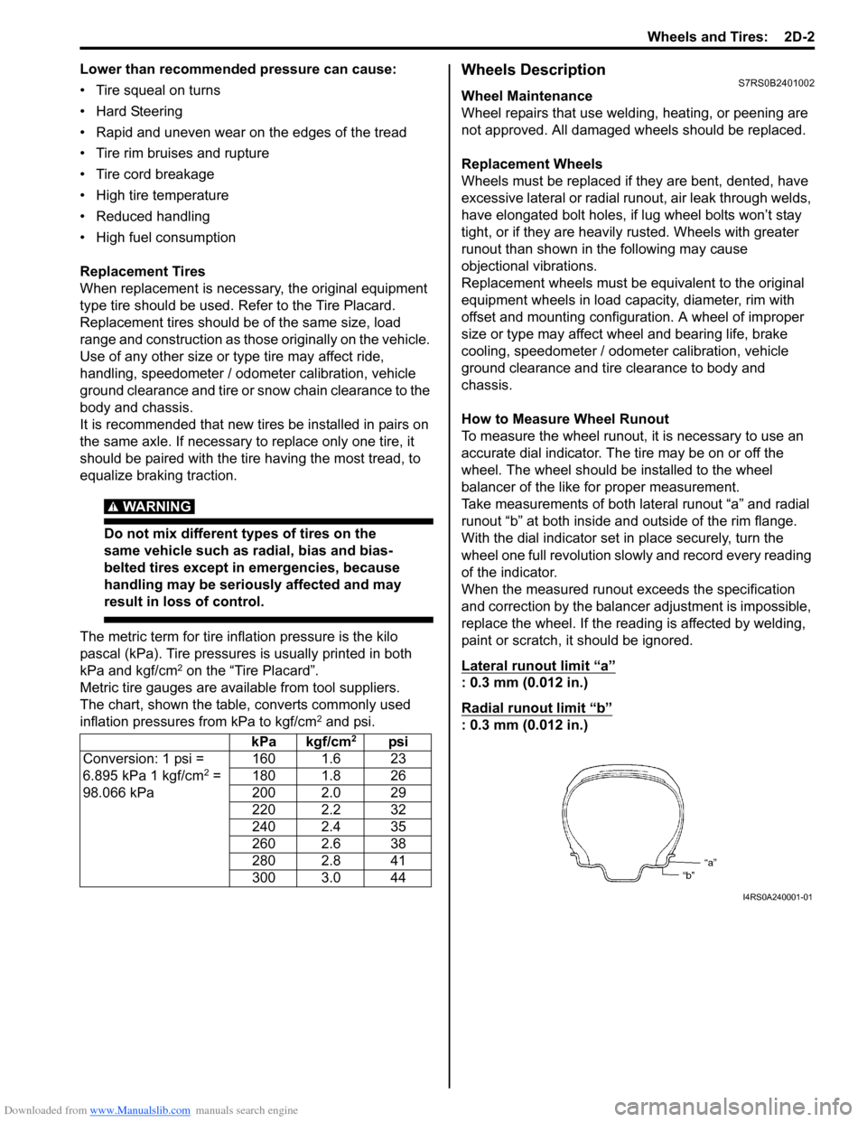
Take measurements of both lateral runout “a” and radial
runout “b” at both inside an d outside of the rim flange.
With the dial indicator set in place securely, turn the
wheel one full revolution slowly and record every reading
of the indicator.
When the measured runout exceeds the specification
and correction by the balancer adjustment is impossible,
replace the wheel. If the reading is affected by welding,
paint or scratch, it should be ignored.
Lateral runout limit “a”
: 0.3 mm (0.012 in.)
Radial runout limit “b”
: 0.3 mm (0.012 in.)
kPa kgf/cm2psi
Conversion: 1 psi =
6.895 kPa 1 kgf/cm
2 =
98.066 kPa 160 1.6 23
180 1.8 26
200 2.0 29
220 2.2 32
240 2.4 35
260 2.6 38
280 2.8 41
300 3.0 44
I4RS0A240001-01
Page 1032 of 1496
Downloaded from www.Manualslib.com manuals search engine 8A-1 Seat Belts:
Restraint
Seat Belts
Precautions
Precautions on Service and Diagnosis of Seat
Belt
S7RS0B8100001
WARNING!
If replacing seat belt is necessary, replace
buckle and seat belt assembly together as a
set. This is for the reason of ensuring locking
of tongue plate with buckle. If these parts are
replaced individually, such a locking
condition may become unreliable. For this
reason, SUZUKI will supply only the spare
buckle and seat belt assembly in a set part.
Before servicing or replacing seat belts, refer to the
following precautionary items.
• Seat belts should be normal relative to strap retractor and buckle portions. • Keep sharp edges and damaging objects away from
belts.
• Avoid bending or damaging any portion of belt buckle or latch plate.
• Do not bleach or dye belt webbing. (Use only mild soap and lukewarm water to clean it.)
• When installing a seat belt anchor bolt, it should be tightened by hand at first to prevent cross-threading
and then to specified torque.
• Do not attempt any repair s on retractor mechanisms
or retractor covers. Replace defective assemblies with
new replacement parts.
• Keep belts dry and clean at all times.
• If there exist any parts in question, replace such parts.
• Replace belts whose webbing is cut or otherwise damaged.
• Do not put anything into trim panel opening which seat belt webbing passes through.
General Description
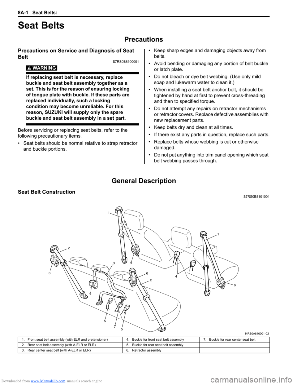
Seat Belt ConstructionS7RS0B8101001
1
1
6
6
6
5
5
7
6
6
2
2
3
4
I4RS0A810001-02
1. Front seat belt assembly (with ELR and pretensioner) 4. Buckle for front seat belt assembly7. Buckle for rear center seat belt
2. Rear seat belt assembly (with A-ELR or ELR) 5. Buckle for rear seat belt assembly
3. Rear center seat belt (with A-ELR or ELR) 6. Retractor assembly
Page 1039 of 1496
Downloaded from www.Manualslib.com manuals search engine Air Bag System: 8B-1
Restraint
Air Bag System
Precautions
Precautions on Service and Diagnosis of Air
Bag System
S7RS0B8200001
WARNING!
• If the air bag system and another vehicle system both need repair, SUZUKI
recommends that the air bag system be
repaired first, to help avoid unintended air
bag system activation.
• Do not modify the steering wheel, dashboard, both front seat or any other on
or around air bag system components.
Modifications can adversely affect air bag
system performance and lead to injury.
• Be sure to follow the procedures described in this section. Failure to follow
procedures could result in possible air bag
system activation, personal injury or
unneeded air bag system repairs.
• WARNING / CAUTION labels are attached on each
part of air bag system components (SDM, air bag
(inflator) modules and seat belt pretensioners). Be
sure to follow the instructions.
• Many of service procedures require disconnection of
“A/BAG” fuse and air bag (inflator) module(s) (driver,
passenger, side of both si des and curtain of both
sides) from initiator circuit to avoid an accidental
deployment.
• Do not apply power to the air bag system unless all components are connected or a diagnostic flow
requests it, as this will set a DTC.
• The “Air Bag Diagnostic S ystem Check” must be the
starting point of any air bag diagnostics. The “Air Bag
Diagnostic System Check” will verify proper “AIR
BAG” warning right operatio n and will lead you to the
correct flow to diagnose any air bag malfunctions.
Bypassing these procedures may result in extended
diagnostic time, incorrect diagnosis, and incorrect
parts replacements. • Never use air bag component parts from another
vehicle.
• If the vehicle will be exposed to temperatures over 93
° C (200 °F) (for example, during a paint baking
process), remove the air bag system components
beforehand to avoid component damage or
unintended system activation.
• When handling the air bag (inflator) modules (driver, passenger, side of both si des and curtain of both
sides), seat belt pretensio ners (driver and passenger),
SDM, forward-sensor or side-sensor, be careful not to
drop it or apply an impact to it. If an excessive impact
was applied (e.g., SDM, forward-sensor and side-
sensor are dropped, air bag (inflator) module is
dropped from a height of 90 cm (3 ft) or more, seat
belt pretensioner (retractor assembly) is dropped from
a height of 30 cm (1 ft) or more), never attempt
disassembly or repair but replace it with a new one.
• When using electric welding, be sure to disconnect air bag (inflator) module connectors (driver, passenger,
side of both sides and curtain of both sides) and seat
belt pretensioner connectors (driver and passenger)
respectively.
• When applying paint around the air bag system related parts, use care so that the harness or
connector will not be expo sed to the paint mist.
• Never expose air bag system component parts directly to hot air (drying or baking the vehicle after
painting) or flames.
WARNING!
When performing service on or around air
bag system components or air bag wiring,
follow the procedures listed in “Disabling Air
Bag System” to temporarily disable the air
bag system.
Failure to follow procedures could result in
possible air bag system activation, personal
injury or unneeded air bag system repairs.
Page 1134 of 1496
Downloaded from www.Manualslib.com manuals search engine 8B-96 Air Bag System:
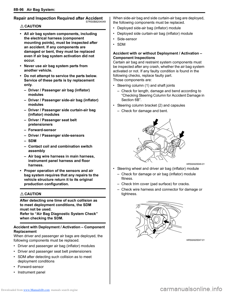
Repair and Inspection Required after AccidentS7RS0B8204049
CAUTION!
• All air bag system components, including the electrical harness (component
mounting points), must be inspected after
an accident. If any components are
damaged or bent, they must be replaced
even if air bag system activation did not
occur.
• Never use air bag system parts from another vehicle.
• Do not attempt to service the parts below. Service of these parts is by replacement
only.
– Driver / Passenger air bag (inflator) modules
– Driver / Passenger side-air bag (inflator) modules
– Driver / Passenger side curtain-air bag (inflator) modules
– Driver / Passenger seat belt pretensioners
–Forward-sensor
– Driver / Passenger side-sensors
–SDM
– Contact coil and combination switch assembly
– Air bag wire harness in main harness, instrument panel harness and floor
harness.
• Proper operation of the sensors and air bag system requires that any repairs to the
vehicle structure return it to its original
production configuration.
CAUTION!
After detecting one time of such collision as
to meet deployment conditions, the SDM
must not be used.
Refer to “Air Bag Diagnostic System Check”
when checking the SDM.
Accident with Deployment / Activation – Component
Replacement
When driver and passenger air bags are deployed, the
following components must be replaced.
• Driver and passenger air bag (inflator) modules
• Driver and passenger seat belt pretensioners
• SDM after detecting such collision as to meet
deployment conditions
• Forward-sensor
• Instrument panel When side-air bag and side curtain-air bag are deployed,
the following components must be replaced.
• Deployed side-air bag (inflator) module
• Deployed side curtain-air bag (inflator) module
• Side-sensor
•SDM
Accident with or without Deployment / Activation –
Component Inspections
Certain air bag and restraint system components must
be inspected after any crash, whether the air bag system
activated or not. If any faul
ty condition is found in the
following checks, replace faulty part.
Those components are:
• Steering column (1) and shaft joints
– Check for length, damage and bend according to “Checking Steering Column for Accident Damage in
Section 6B”.
• Steering column bracket (2) and capsules – Check for damage and bent.
• Steering wheel and driver air bag (inflator) module – Check for damage or air bag (inflator) module fitness.
– Check trim cover (pad surface) for cracks.
– Check wire harness and connector for damage or tightness.
2
1
I4RS0A820046-01
I4RS0A820047-01
Page 1168 of 1496

Downloaded from www.Manualslib.com manuals search engine 9-ii Table of Contents
List of Connectors ........................................... 9A-103
C Connector .................................................... 9A-103
D Connector (M16A engine) ........................... 9A-104
E Connector .................................................... 9A-104
G Connector .................................................... 9A-106
J Connector ..................................................... 9A-108
K Connector .................................................... 9A-109
L Connector..................................................... 9A-109
M Connector (SPORT model) ......................... 9A-111
O Connector .................................................... 9A-111
R Connector .................................................... 9A-111
Lighting Systems .................................... 9B-1
Component Location ........... ................................9B-1
Lighting System Component s Location............... 9B-1
Interior Light System Location............................. 9B-2
Diagnostic Information and Procedures ............ 9B-2 Headlight Symptom Diagnosis ............................ 9B-2
Headlight Leveling System Symptom Diagnosis (If Equipped) ..................................... 9B-2
Turn Signal and Hazard Warning Light Symptom Diagnosis .......................................... 9B-3
Clearance, Tail and License Plate Light Symptom Diagnosis .......................................... 9B-3
Back-Up Light Symptom Diagnosis..................... 9B-4
Brake Light Symptom Diagnosis ......................... 9B-4
Front Fog Light Symptom Diagnosis (If Equipped) .......................................................... 9B-4
Interior Light Symptom Diagnosis ....................... 9B-5
Repair Instructions ..............................................9B-5 Headlight Housing Removal and Installation ...... 9B-5
Headlight Bulb Replacemen t............................... 9B-6
Headlight Aiming Adjustment with Screen .......... 9B-6
Headlight Switch (in Lighting Switch) Removal and Installation ................................... 9B-8
Headlight Switch (in Lighting Switch) Inspection .......................................................... 9B-8
Hazard Warning Switch Removal and Installation ......................................................... 9B-8
Hazard Warning Switch Inspection ..................... 9B-9
Brake Light Switch Inspection ............................. 9B-9
Turn Signal Light Switch (in Lighting Switch) Removal and Installation ................................... 9B-9
Turn Signal Light Switch (in Lighting Switch) Inspection .......................................................... 9B-9
Turn Signal and Hazard Warning Relay Removal and Installation ................................... 9B-9
Turn Signal and Hazard Warning Relay Inspection ........................................................ 9B-10
License Light Removal and Installation............. 9B-10
Front Fog Light Removal and Installation (If Equipped) ........................................................ 9B-11
Front Fog Light Bulb Replacement (If Equipped) ........................................................ 9B-11
Front Fog Light Switch Inspection (If Equipped) ........................................................ 9B-11
Front Fog Light Relay Inspection (If Equipped) ........................................................ 9B-11
Front Fog Light Aiming Adjustment with Screen (If Equipped) ....................................... 9B-12 Headlight Leveling Switch Inspection (If
Equipped) ........................................................ 9B-13
Headlight Leveling Actuator Inspection (If Equipped) ........................................................ 9B-13
Instrumentation / Driver Info. / Horn ...... 9C-1
Precautions ...........................................................9C-1 Precautions in Diagnosing Troubles for Combination Meter ............................................9C-1
General Description .............................................9C-1 CAN Communication System Description...........9C-1
Auto Volume Co ntrol System Description (If
Equipped) ..........................................................9C-3
Schematic and Routing Diagram ........................9C-4 Combination Meter Circuit Diagram ....................9C-4
Component Location ............ ...............................9C-6
Audio System Component Location ....................9C-6
Diagnostic Information and Procedures ............9C-6 Speedometer and VSS Symp tom Diagnosis ......9C-6
Tachometer Symptom Diagnosis ........................9C-6
Engine Coolant Temperature (ECT) Meter Symptom Diagnosis ..........................................9C-7
Fuel Meter Symptom Diagnosis ..........................9C-7
Low Fuel Warning Light Symptom Diagnosis .....9C-7
Oil Pressure Warning Light Symptom Diagnosis ..........................................................9C-8
Brake and Parking Brake Warning Light Symptom Diagnosis ..........................................9C-8
Seat Belt Reminder Light Symptom Diagnosis (If Equipped)......................................................9C-8
A/T Shift Position Indicator Symptom Diagnosis (A/T Model).......................................9C-9
Charge Warning Light Sy mptom Diagnosis ........9C-9
Main Beam (High Beam) Indicator Symptom Diagnosis ..........................................................9C-9
Warning Buzzer Circuit Sy mptom Diagnosis ....9C-10
Cigarette Lighter Symptom Diagnosis (If Equipped) ........................................................9C-10
Horn Symptom Diagnosis .................................9C-10
Information Display Symptom Diagnosis (If Equipped) ........................................................9C-11
Clock Symptom Diagnosis (If Equipped)...........9C-12
Audio System Symptom Diagnosis (If Equipped) ........................................................9C-12
Remote Audio Control Switch Symptom Diagnosis (If Equipped) ...................................9C-13
Navigation Symptom Diagnosis (If Equipped)...9C-14
Repair Instructions ............ ................................9C-14
Ignition Switch Removal and Installation...........9C-14
Ignition Switch Inspection..................................9C-14
Combination Meter Removal and Installation ...9C-15
Fuel Level Sensor Removal and Installation .....9C-15
Fuel Level Sensor Inspection ............................9C-15
Oil Pressure Switch Remova l and Installation ..9C-15
Oil Pressure Switch Inspec tion .........................9C-16
Engine Coolant Temperature (ECT) Sensor Inspection ........................................................9C-16
Brake Fluid Level Switch Inspection .................9C-16
Parking Brake Switch Inspec tion.......................9C-16